EP0004012A2 - Dispositif de verrouillage des portes d'appareils électriques - Google Patents
Dispositif de verrouillage des portes d'appareils électriques Download PDFInfo
- Publication number
- EP0004012A2 EP0004012A2 EP79100562A EP79100562A EP0004012A2 EP 0004012 A2 EP0004012 A2 EP 0004012A2 EP 79100562 A EP79100562 A EP 79100562A EP 79100562 A EP79100562 A EP 79100562A EP 0004012 A2 EP0004012 A2 EP 0004012A2
- Authority
- EP
- European Patent Office
- Prior art keywords
- locking
- housing
- lock plate
- switch
- door
- Prior art date
- Legal status (The legal status is an assumption and is not a legal conclusion. Google has not performed a legal analysis and makes no representation as to the accuracy of the status listed.)
- Granted
Links
- 238000005406 washing Methods 0.000 claims abstract description 3
- 238000006073 displacement reaction Methods 0.000 claims description 47
- 238000005192 partition Methods 0.000 claims description 5
- 238000010438 heat treatment Methods 0.000 abstract description 11
- 230000000903 blocking effect Effects 0.000 abstract description 3
- 238000004804 winding Methods 0.000 description 7
- 238000013461 design Methods 0.000 description 5
- 238000005452 bending Methods 0.000 description 3
- 230000005284 excitation Effects 0.000 description 3
- 238000004519 manufacturing process Methods 0.000 description 3
- 239000002184 metal Substances 0.000 description 3
- 238000010276 construction Methods 0.000 description 2
- 238000009434 installation Methods 0.000 description 2
- 238000012546 transfer Methods 0.000 description 2
- 208000027418 Wounds and injury Diseases 0.000 description 1
- 230000004913 activation Effects 0.000 description 1
- 230000006978 adaptation Effects 0.000 description 1
- 238000002788 crimping Methods 0.000 description 1
- 230000006378 damage Effects 0.000 description 1
- 238000007654 immersion Methods 0.000 description 1
- 208000014674 injury Diseases 0.000 description 1
- 238000003780 insertion Methods 0.000 description 1
- 230000037431 insertion Effects 0.000 description 1
- 230000013011 mating Effects 0.000 description 1
- 238000000034 method Methods 0.000 description 1
- 238000004080 punching Methods 0.000 description 1
- 238000000926 separation method Methods 0.000 description 1
- 238000012549 training Methods 0.000 description 1
- 230000001960 triggered effect Effects 0.000 description 1
Images


Classifications
-
- D—TEXTILES; PAPER
- D06—TREATMENT OF TEXTILES OR THE LIKE; LAUNDERING; FLEXIBLE MATERIALS NOT OTHERWISE PROVIDED FOR
- D06F—LAUNDERING, DRYING, IRONING, PRESSING OR FOLDING TEXTILE ARTICLES
- D06F37/00—Details specific to washing machines covered by groups D06F21/00 - D06F25/00
- D06F37/42—Safety arrangements, e.g. for stopping rotation of the receptacle upon opening of the casing door
Definitions
- the invention relates to a door locking device of the type characterized in the preamble of claim 1.
- Such door locking devices serve to prevent the risk of injury by blocking the device access during device operation.
- the door lock hook engages to hold the door in the closed position behind the edge of a window-like recess which is introduced into a lateral arm of the cover plate of the housing of the locking device.
- the door lock hook When the door lock hook is inserted into the window-like recess, it is immersed in a window-like recess of the lock plate which is covered by the cover plate recess and which is mounted within the cover plate of the housing at right angles to the immersion direction of the door lock hook, namely in the rear grip direction of the door lock hook.
- the lock plate is displaced within its guide.
- the lock plate is provided with a further passage recess which, in the shifting end position of the lock plate, which corresponds to the closed position of the door lock hook, is in overlap with a locking slide which is displaceably mounted within the housing.
- the locking slide is placed on the end of a contact spring of a switch for a device circuit, which bends against a housing-fixed mating contact due to the deflection of a bimetal and at the same time causes the locking slide to move.
- the locking slide dips into the recess in the lock plate which overlaps with it and blocks its return movement into the overlapping position with the recess in the extension arm of the cover plate of the housing.
- the recess in the lock plate intended for receiving the door lock hook takes up a position in this locking position, which makes it impossible for the lock hook to escape from its rear engagement position behind the edge of the recess in the arm of the housing cover. The door cannot be opened when the lock plate is locked.
- the heating of the metal strip of the locking device must be switched on after the completion of the closing path of the door lock hook by a separate switch.
- the bending out of the bimetallic strip then leads synchronously to the switching on of a device circuit and to the blocking of the mobility of the lock plate in the door lock hook holding position of displacement.
- the separate switch for the bimetal heating must also be installed on the device frame and adjusted in relation to the lock plate.
- this door locking device requires that it be adapted to the installation conditions on the respective machine.
- the invention is based on the object to provide a door locking device of the type mentioned, which contains all the parts necessary for their function and which is adapted to individual installation conditions on different machines. This object is achieved by the characterizing part of claim 1.
- the housing containing all the functional parts of the locking device can simply be riveted to a frame built according to individual requirements, the adaptation to the individual requirements of the machine being possible solely by choosing a lock plate which has been modified with regard to its design, without this having to be done when the locking device is being assembled requires other individual consideration.
- the housing which contains the drive and locking parts, is a uniformly designed part that can be mass-produced and delivered to the device manufacturer.
- a lock plate selected in accordance with the individual device requirements, for example rivets the housing to the device frame in this position.
- Adapting the shape the lock plate to the individual requirements of the electrical device presents no difficulties, because the lock plate can be produced as a simple stamped part from a sheet metal.
- the characteristics of claim 2 ensure that the lock plate is properly guided without requiring special training of the device frame.
- the characterizing part of claim 3 enables a particularly flat construction of the device perpendicular to the lock plate. As a result, the device can also be used advantageously in confined spaces.
- the locking projections are arranged in all displacement positions of the locking slide in the overlap area of the lock plate. They do not protrude laterally beyond the lock plate, which also serves to economize on space.
- the projection projections of the locking slide possibly intercept directly at right angles to the direction of displacement of the lock plate on these displacement pressures caused by the guide projections. Tilting of the lock plate due to its locking gelung on the part of the locking slide within their leadership is therefore not possible.
- the guide projections additionally fix the distance between the lock plate-side housing wall and the device frame and also provide guidance of the lock plate between these parts.
- the characterizing part of claim 8 ensures a space-saving arrangement of the locking slide within the housing. Due to the further feature of claim 9, the lock plate is locked in a known manner in the optimal vicinity of the door lock hook, so that the lock plate can be made relatively short in this direction.
- the locking slide is characterized by an easy to manufacture and space-saving in the longitudinal direction of the lock plate design.
- the characterizing part of claim 17 enables a particularly space-saving construction of the device housing. Its maximum width only needs to be slightly larger than that of the lock plate in order to allow lateral guidance.
- the characteristic of claim 18 guarantees a spatial, rollover-proof separation of the essential individual parts of the control drive for the locking slide.
- the characterizing part of claim 19 favors the flat, space-saving design of the housing already sought by the feature of claim 17.
- the characterizing part of claim 20 enables a cost-saving production of the device.
- the features according to at least one of claims 21 to 23 make it possible, without changing the individual parts of the device by simply arranging the door lock switch within its recess, to make the device usable for door locks in accordance with the invention in which the door lock hook is in the housing is turned away into its closed end position in such a way that not - as is generally the case - the lock plate with the transfer of the lock hook into its closed end position in the direction of the housing but in the direction of Housing is moved away while maintaining the longitudinal axis of the sliding movement.
- the door locking device according to the invention can be adapted even better to individual conditions on the electrical device.
- the characterizing part of claim 24 also serves to ensure a space-saving design of the device according to the invention.
- the electrical connections of the device can be connected with a handle.
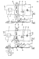
- the lock hook 1 of the T is not shown in detail, is at the closing of the door for transferring in its closed position along the direction indicated by an arrow trajectory 2 in shown in Fig 4 ÜR - transferred shown closed end -.
- Upper panel of the lock hook 1. Here, it dips into a window-like opening 3 of the frame 4, which is part of the electrical device, for example part of a washing machine frame.
- the lock hook 1 engages with its locking projection 5 on a side edge of the window-like opening 3 in the frame 4. Thereafter, it is no longer possible to move the lock hook 1 in its longitudinal direction 6 from the closed end position to move.
- the lock plate 8 is used. It also serves for the purpose outside the operation or the ready position of the electrical device to release the opening and closing movement of the lock hook 1, so that it can be operated solely by the (not shown) door handle of the door. Outside the operating position or the ready position of the electrical device, the lock plate 8 is therefore ineffective with respect to the lock hook 1.
- the lock plate 8 is mounted in the direction of displacement 7 parallel to the frame 4 on its - with reference to FIGS. 2, 4, 6 and 8 - rear engaging side. It lies on the surface of the frame 4, which - just like the lock plate as a whole - is flat in this area in order to make it possible to provide a leading support for the lock plate 8.
- the lock plate 8 is also provided in the area of the opening 3 in the frame 4 with a window-like passage opening 9. With regard to its size, the opening 9 of the lock plate 8 corresponds to the opening 3 in the frame 4. In a sliding end position of the lock plate 8, its opening 9 overlaps with the window-like opening 3 of the frame 4.
- the openings 3 point in the direction of projection of the locking projection 5 of the lock hook 1 , 9 of the frame 4 or the lock plate 8 have a clear cross-sectional width 10, which corresponds approximately to the length 11 of the head of the lock hook 1 measured in this direction in the region of the locking projection 5.
- the lock hook 1 with its head can freely penetrate through the opening 3 of the frame 4 and into the opening 9 of the lock plate 8.
- the lock hook 1 is enclosed with its head in the direction of displacement 7 relative to the lock plate 8 essentially immovably.
- the side walls 12, 13 opposing the direction of displacement 7 are formed by bending the sheet metal blank of the lock plate 8. These upward bends can be carried out without difficulty when punching out the opening 9.
- the lock plate 8 Due to the transfer of the lock hook 1 into the closed end position shown in FIG. 4 caused by the door handle (not shown), the lock plate 8 is shifted to the right in the displacement direction 7 with reference to FIG. 4. The locking of the lock plate 8 in this displacement end position causes the lock hook 1 to lock, with the result that it cannot be moved in the shifting direction 7 with respect to FIG. 4 to the left for the duration of the lock, that is to say the door cannot be opened.
- the actual locking device 14 is used to lock the lock plate 8 in the closed end position.
- the locking drive In addition to the locking drive, it contains a door lock switch 15 which triggers this, depending on the closing movement of the lock hook 1 and thus the displacement movement of the lock plate 8, which actuates the lock plate 8 triggers, and a door lock switch 16, which is only triggered when the locking end position of the locking slide 17 is reached and produces the operational readiness of the electrical device or - depending on its circuit - carries out its activation.
- the switch-on takes place only at the moment when the locking of the lock plate 8 is ensured in the closed position of the lock hook 1. This is based on the design of the locking switch as a so-called snap switch, which will be described in detail later.
- the locking slide 17 of the locking device 14 is parallel to the plane of the lock plate 8, perpendicular to the direction of displacement 7, ie in the direction of arrow 18 within the device housing 19 stored in cash. With two locking projections 20, it penetrates the lock plate-side base 21 of the housing 14 in two through grooves 22 one behind the other in the direction of the arrow 18 and thus in the direction of displacement 7 of the lock plate 8 is particularly space-saving.
- the two locking projections 20 each protrude into a window-like recess 23 in the lock plate 8.
- the length of the recesses 23 in the direction of displacement 7 of the lock plate 8 corresponds to at least that of a displacement stroke of the lock plate 8 plus the width of a locking projection 20.
- the recesses 23 are arranged relative to the locking projections 20 of the locking slide 17 such that in the open position of the locking slide 17, the locking projections 20 of the sliding movement the lock plate 8 do not hinder between their two displacement end positions. This position is shown in Fig. 1.
- Running in the locking direction of the locking projections 20 of the locking slide 17 and in the closed end position of the lock plate 8 with the locking projections 20 overlapping are the side boundary edges of the recesses 23 in the form of one opposite the locking direction of the locking slide 17 Lock groove 24 enlarged.
- the locking grooves 24 have approximately the cross-sectional shape of the locking projections 20 of the locking slide 17. If the lock plate 8 is in the closed end position and the locking slide 17 is moved into its locking position, the locking projections 20 dip into the locking grooves 24 of the recesses 23 and prevent any displacement of the lock plate 8 in the displacement direction 7 (FIG. 3) in this position. In the open position corresponding to the retracted position (FIG. 1) of the locking projections 20, however, the lock plate 8 can move freely in the direction of displacement 7. In the two displacement end positions, the locking projections 20 each lie on one of the side edges lying in the displacement direction 7 . Recesses 23 on.
- the projection 25 extends through the bottom 21 of the device housing 19 in an elongated hole 27 extending in the direction of displacement 7.
- the projection 25 engages in a window-like passage recess 28 of the lock plate 8 with a play seat.
- the lock plate 8 is between the outer surface of the bottom 21 and the surface of the device frame 4 as between two over the outer surface of the bottom 21 from the housing in the direction of the device frame 4 projecting guide projections 29 of the housing 19. It rests with its two side edges 30 running parallel to one another in the direction of displacement 7 on the inner sides 31 of the guide projections 29, which also run parallel to one another.
- the guide projections 29 lie in the longitudinal plane of the locking slide 17 with the same distance on both sides of the central longitudinal axis 32 of the locking device.
- the guide projections 29 are designed as set-up feet opposite the device frame 4. They each have a passage opening 33 running approximately perpendicular to the bottom 21 for the passage of fastening rivets with which the housing 19 can be riveted to the device frame 4. Since the locking slide 17 runs directly next to the housing wall 34 on the lock hook side, the guide projections 29 and the set-up feet of the housing 19 also lie on the housing end assigned to the locking slide 17.
- a third support projection 35 for supporting the housing 19 on the device frame 4 protrudes from the bottom 21 of the housing 19 outside the overlap region of the lock plate 8 in the region of the central longitudinal axis 32. This provides three-point support.
- the support projection 35 is also provided with a recess 36 for engaging a fastening means to the device frame 4.
- the embodiment of the door locking device according to FIGS. 5-8 differs from that according to FIG 1 - 4 by the exactly opposite course of the movement path 2 of the lock hook 1 and the exactly opposite orientation of the locking projection 5 of the lock hook 1 in the direction of displacement 7 of the lock plate 8.
- 6 8 engages behind the locking projection 5 of the lock hook 1 the edge of the window-like frame opening 3 with reference to FIGS. 6 and 8 to the left and not - as in the embodiment according to FIGS. 2 and 4 - to the right.
- the locking grooves 24 extending from the window-like recesses 23 in the lock plate 8 in the direction of displacement 18 of the locking slide 17 are not arranged in the lower left area with respect to FIGS.
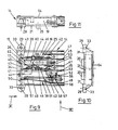
- the bimetal control, designated overall by 38, the door closing switch 15, the locking switch 16 which switches the device circuit and the slide switch 26 are in the housing 19 next to one another and with respect to their longitudinal extension or longest dimension essentially in the direction of displacement 7 of the lock plate 8, that is to say at right angles to the direction of displacement of the locking slide 17 , on the same Side next to the locking slide 17 arranged together with this in a plane parallel to the bottom 21.
- Bimetal control 38, locking switch 16, door closing switch 15 and slide switch 26 are each accommodated in a separate recess in the housing 19, the partitions 39, 40, 41 of which each run parallel to one another.
- the planes of movement of the bimetal control 38, the locking switch 16 and the door closing switch 15 also lie in a plane running parallel to the floor 21.
- Locking and door closing switches 16 and 15 are known, preferably identically designed snap switches.
- the movable contact bridge 42 and the snap actuating part 43 of these snap switches are each formed by a rigid, band-shaped, metallic component.
- the contact bridge 42 and snap actuating part 43 are each stored in V-shaped notches in the two opposite side edges of a bearing 44.
- the bearings 44 are integrally formed on the inner ends of the electrical connections 45.
- the bearings 44 are formed by a U-shaped bending of lateral projections of the connections 45 which run perpendicular to the plane of the drawing in FIG. 9.
- the movable contact bridge 42 and the snap actuating part 43 of the two closing switches 15 and locking switches 16 forming snap switches are directly connected to each other by a tension spring 46.
- the tension spring pulls the movable contact bridge 42 and the snap-actuator 43 each s with its bearing side edges in the V-conveyor mi g notches of the bearing 44 into it.
- the pan away from both the snap actuation part 41 and the movable contact bridge 42 is delimited on both sides of the dead center by corresponding housing stops or by the fixed contacts 47 cooperating with the contact bridges 42.
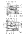
- the bimetal control 38 is installed in the lower housing recess.
- a leaf spring 49 is fastened, which projects with its free end into a passage slot 50 of the locking slide 17 approximately in a form-fitting manner.
- the unexcited bimetal 51 counteracts the pretension of the leaf spring 49, so that the starting position shown in FIG. 9 is adopted.
- the heating coil 52 is wound around the bimetal 51.
- a wire end 53 of the winding is connected to the terminal 45 of the door closing switch 15.
- the other wire end 54 is connected directly to the free end of the bimetal 51.
- the bimetal 51 is firmly riveted into the housing 19 with the crimp sleeve 55.
- An adjusting screw 56 protrudes through the crimping sleeve, the conical end of which can be used to adjust the pretension of the bimetal via the nose 57 striving at approximately right angles from the bimetal 51.
- a series resistor 58 or a diode is located between bimetal 51 and terminal 48. In the rest position, the series resistor is short-circuited by the contact point formed between the bimetal 51 and the leaf spring 49.
- the heating winding 52 is directly connected to this voltage.
- the bimetal 51 is heated and moves upwards (FIG. 13). With this movement, the leaf spring 49 becomes effective and moves the locking slide 17 into its locking position shown in FIG. 13.
- the contact point 59 existing between the bimetal 51 and the leaf spring 49 is opened in the locking end position of the locking slide 17.
- the series resistor 58 is connected in series with the heating winding 52. With a constant voltage source, a smaller current now flows.
- the bimetal 51 is only heated to the extent that the position according to FIG. 13 is maintained.
- the slide switch 26 is provided with a recess 60 which penetrates it in the direction of displacement 18 of the locking slide 17 in a window-like manner.
- the side wall facing the door closing switch 15 of the housing recess receiving the slide switch 26 is provided in the movement area of the slide switch recess 60 with an opening 61 for the passage of a driver 62, which is firmly connected to the snap actuating part 43 of the door closing switch 15 and serves for its movement.
- the driver 62 is bent in an S-shape and projects with its free S-leg into the passage recess 60 of the slide switch 26.
- the end faces of the partition walls 39, 40, 41 of the housing recesses facing the locking slide 17 for receiving the two switches 15, 16 are designed as guide parts for the locking slide 16.
- All connections 45, 48 and fixed contacts 47 of the bimetallic control 38, the locking switch 16 and the door closing switch 15 are passed through the side wall of the housing 19 opposite the locking slide 17 in the direction of displacement 7 of the lock plate 8.
- the housing 19 can be closed by a cover 64 on its side opposite the base 21.
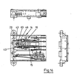
- the embodiment of the locking device 14 according to FIGS. 14-16 differs from the embodiment according to FIGS. 9-13 only in that the contacts of the door closing switch 15 in a 180 ° around the central longitudinal axis 65 of the housing recess 66 for receiving the door closing switch 15 pivoted position are arranged in the plane of movement of the door closing switch 15 running parallel to the floor 21. Furthermore, the driver 62 is fastened on the inside of the bearing 44 to the snap actuating part 43 of the door closing switch 15. It extends with its free S-leg in the same way as in the embodiment according to FIGS. 9-13 into the recess 60 of the slide switch 26 mounted in the same way as in the embodiment according to FIGS. 9-13. Only the return spring 63 acting on the slide switch 26 is located on the other end face of the slide switch 26, in order to counteract the displacement of the slide switch 26 when the lock plate 8 is transferred from its open to the closed position.
- the locking device works as follows:
- the bimetal swings out in the direction of the arrow 67 (FIGS. 13, 16).
- the leaf spring 49 pivots in the manner described in detail above under the pressure of its bias also in the direction of arrow 67 and thereby moves the locking slide 17 into its locking end position in which its locking projections 20 engage in the locking grooves 24 of the recesses 23 in the lock plate 8 .
- the snap actuating part 43 of the locking switch 16 is transferred into its other snap end position, whereby the movable contact bridge 42 of the locking switch 16 is taken along and brought into contact with the fixed contact 47 assigned to it.
- the circuit of the locking switch 16 is thus closed.
- the electrical device is switched on or is now in the ready-to-switch-on position after the locking of the lock hook 1 in its closed end position is ensured.
- the return spring acting on the slide switch 26 in the direction of its initial position serves to facilitate assembly so that the projection 25 always assumes the position corresponding to the open position of the device.
Landscapes
- Engineering & Computer Science (AREA)
- Textile Engineering (AREA)
- Casings For Electric Apparatus (AREA)
Applications Claiming Priority (2)
| Application Number | Priority Date | Filing Date | Title |
|---|---|---|---|
| DE2810667A DE2810667C2 (de) | 1978-03-11 | 1978-03-11 | Türverriegelungsvorrichtung für elektrische Geräte |
| DE2810667 | 1978-03-11 |
Publications (3)
| Publication Number | Publication Date |
|---|---|
| EP0004012A2 true EP0004012A2 (fr) | 1979-09-19 |
| EP0004012A3 EP0004012A3 (en) | 1979-10-17 |
| EP0004012B1 EP0004012B1 (fr) | 1981-09-02 |
Family
ID=6034194
Family Applications (1)
| Application Number | Title | Priority Date | Filing Date |
|---|---|---|---|
| EP79100562A Expired EP0004012B1 (fr) | 1978-03-11 | 1979-02-24 | Dispositif de verrouillage des portes d'appareils électriques |
Country Status (3)
| Country | Link |
|---|---|
| EP (1) | EP0004012B1 (fr) |
| AT (1) | AT370145B (fr) |
| DE (1) | DE2810667C2 (fr) |
Cited By (3)
| Publication number | Priority date | Publication date | Assignee | Title |
|---|---|---|---|---|
| FR2566438A1 (fr) * | 1984-06-22 | 1985-12-27 | Texas Instruments Italia Spa | Dispositif pour la commande de l'alimentation electrique et pour le verrouillage a deblocage retarde des portes de machines a laver ou similaires |
| EP1418266A3 (fr) * | 2002-11-08 | 2006-06-28 | Elettrotecnica Rold Srl | Dispositif pour le verrouillage d'une porte de lave-linge |
| EP1726750A1 (fr) * | 2005-02-25 | 2006-11-29 | Elettrotecnica Rold Srl | Dispositif de verrouillage d'une porte à hublot pour une machine à laver |
Families Citing this family (2)
| Publication number | Priority date | Publication date | Assignee | Title |
|---|---|---|---|---|
| DE3008756C2 (de) * | 1980-03-07 | 1985-08-08 | Kiekert GmbH & Co KG, 5628 Heiligenhaus | Verriegelungsvorrichtung für eine Haushaltsmaschine o.dgl. |
| US9957657B2 (en) * | 2015-01-30 | 2018-05-01 | Emz-Hanauer Gmbh & Co. Kgaa | Appliance lock |
Family Cites Families (7)
| Publication number | Priority date | Publication date | Assignee | Title |
|---|---|---|---|---|
| DE7807461U1 (de) * | 1978-08-03 | Ellenberger & Poensgen Gmbh, 8503 Altdorf | Türverriegelungsvorrichtung für elektrische Geräte | |
| GB1252767A (fr) * | 1967-12-15 | 1971-11-10 | ||
| DE1815720C3 (de) * | 1968-12-13 | 1980-06-12 | Bosch-Siemens Hausgeraete Gmbh, 7000 Stuttgart | Verriegelungseinrichtung fur die Beschickungstur einer Waschmaschine |
| CH520225A (de) * | 1969-10-27 | 1972-03-15 | Ellenberger & Poensgen | Elektrothermisches Relais zur Verriegelung von Waschmaschinentüren |
| BE791863A (fr) * | 1971-11-26 | 1973-03-16 | Rocchitelli Onofrio | Appareil pour le verrouillage et le deverrouillage temporise dedispositifs de fermeture de portes de machines |
| IT948518B (it) * | 1971-12-17 | 1973-06-11 | Feme | Dispositivo per il blocco con consenso ritardato alla apertura du un portello od altro organo di accesso all interno di apparecchia ture in genere e macchine lavatri ci in particolare |
| IT994158B (it) * | 1973-08-21 | 1975-10-20 | Texas Instruments Italia Spa | Dispositivo di bloccaggio con interruttore ritardatore termico ad azionamento voltmetrico per sportelli |
-
1978
- 1978-03-11 DE DE2810667A patent/DE2810667C2/de not_active Expired
-
1979
- 1979-02-16 AT AT0119679A patent/AT370145B/de not_active IP Right Cessation
- 1979-02-24 EP EP79100562A patent/EP0004012B1/fr not_active Expired
Cited By (3)
| Publication number | Priority date | Publication date | Assignee | Title |
|---|---|---|---|---|
| FR2566438A1 (fr) * | 1984-06-22 | 1985-12-27 | Texas Instruments Italia Spa | Dispositif pour la commande de l'alimentation electrique et pour le verrouillage a deblocage retarde des portes de machines a laver ou similaires |
| EP1418266A3 (fr) * | 2002-11-08 | 2006-06-28 | Elettrotecnica Rold Srl | Dispositif pour le verrouillage d'une porte de lave-linge |
| EP1726750A1 (fr) * | 2005-02-25 | 2006-11-29 | Elettrotecnica Rold Srl | Dispositif de verrouillage d'une porte à hublot pour une machine à laver |
Also Published As
| Publication number | Publication date |
|---|---|
| DE2810667C2 (de) | 1982-07-29 |
| ATA119679A (de) | 1982-07-15 |
| DE2810667A1 (de) | 1979-09-13 |
| EP0004012A3 (en) | 1979-10-17 |
| EP0004012B1 (fr) | 1981-09-02 |
| AT370145B (de) | 1983-03-10 |
Similar Documents
| Publication | Publication Date | Title |
|---|---|---|
| DE2725263A1 (de) | Bimetallunterbrecherschalter | |
| EP0268098B1 (fr) | Appareil de commutation électrique, en particulier pour commande de puissance | |
| DE19708609C2 (de) | Schiebeschalter | |
| DE4129938C2 (fr) | ||
| EP1074030B1 (fr) | Appareil de commutation comportant un module a chambre de coupure | |
| DE2901246C2 (de) | Elektrische Schaltvorrichtung | |
| DE2619002C3 (de) | Elektromagnetisches Klappankerrelais | |
| DE2449457C3 (de) | Klappankerrelais | |
| DE3233909A1 (de) | Schnappvorrichtung, insbesondere elektrischer schnappschalter | |
| DE1465705B1 (de) | Elektrischer Schnappschalter mit Drueckerhebel | |
| DE3327675A1 (de) | Schaltkammer fuer nockenschalter | |
| EP0004012A2 (fr) | Dispositif de verrouillage des portes d'appareils électriques | |
| DE2541922B2 (de) | Verriegelbarer Drucktastenschalter | |
| EP0500546B1 (fr) | Verrouillage pour un tiroir enfichable | |
| DE2256721A1 (de) | Zusatzgeraet zur verklinkung eines relais | |
| DE7807461U1 (de) | Türverriegelungsvorrichtung für elektrische Geräte | |
| DE2739928C3 (de) | Temperaturabhängig arbeitender elektrischer Schalter in Flachbauweise | |
| EP0091687A1 (fr) | Relais électromagnétique | |
| EP0494278B1 (fr) | Commutateur electrique | |
| DE2107804C3 (de) | Elektrischer Steuerschalter | |
| EP0003973B1 (fr) | Interrupteur de puissance à basse tension avec déclencheur électromagnétique | |
| WO1998010456A1 (fr) | Disjoncteur de surintensite | |
| EP0043406B1 (fr) | Elément interrupteur de protection pour être ajouté à un appareil interrupteur construit comme interrupteur rotatif | |
| DE2741292C2 (de) | Tastenschalter | |
| DE1465705C (de) | Elektrischer Schnappschalter mit Druckerhebel |
Legal Events
| Date | Code | Title | Description |
|---|---|---|---|
| PUAI | Public reference made under article 153(3) epc to a published international application that has entered the european phase |
Free format text: ORIGINAL CODE: 0009012 |
|
| PUAL | Search report despatched |
Free format text: ORIGINAL CODE: 0009013 |
|
| AK | Designated contracting states |
Designated state(s): CH FR GB IT SE |
|
| AK | Designated contracting states |
Designated state(s): CH FR GB IT SE |
|
| 17P | Request for examination filed | ||
| ITCL | It: translation for ep claims filed |
Representative=s name: RICCARDI SERGIO & CO. |
|
| ITF | It: translation for a ep patent filed | ||
| GRAA | (expected) grant |
Free format text: ORIGINAL CODE: 0009210 |
|
| AK | Designated contracting states |
Designated state(s): CH FR GB IT SE |
|
| PGFP | Annual fee paid to national office [announced via postgrant information from national office to epo] |
Ref country code: FR Payment date: 19840305 Year of fee payment: 6 |
|
| PGFP | Annual fee paid to national office [announced via postgrant information from national office to epo] |
Ref country code: SE Payment date: 19840331 Year of fee payment: 6 |
|
| PGFP | Annual fee paid to national office [announced via postgrant information from national office to epo] |
Ref country code: CH Payment date: 19840425 Year of fee payment: 6 |
|
| PG25 | Lapsed in a contracting state [announced via postgrant information from national office to epo] |
Ref country code: SE Effective date: 19850225 |
|
| PG25 | Lapsed in a contracting state [announced via postgrant information from national office to epo] |
Ref country code: CH Effective date: 19850228 |
|
| GBPC | Gb: european patent ceased through non-payment of renewal fee | ||
| PG25 | Lapsed in a contracting state [announced via postgrant information from national office to epo] |
Ref country code: FR Free format text: LAPSE BECAUSE OF NON-PAYMENT OF DUE FEES Effective date: 19851031 |
|
| REG | Reference to a national code |
Ref country code: CH Ref legal event code: PL |
|
| REG | Reference to a national code |
Ref country code: FR Ref legal event code: ST |
|
| PG25 | Lapsed in a contracting state [announced via postgrant information from national office to epo] |
Ref country code: GB Effective date: 19881117 |
|
| EUG | Se: european patent has lapsed |
Ref document number: 79100562.2 Effective date: 19860129 |
|
| PLBE | No opposition filed within time limit |
Free format text: ORIGINAL CODE: 0009261 |
|
| STAA | Information on the status of an ep patent application or granted ep patent |
Free format text: STATUS: NO OPPOSITION FILED WITHIN TIME LIMIT |