EP0004146B1 - Elektrischer Verbinder mit Presshülse - Google Patents
Elektrischer Verbinder mit Presshülse Download PDFInfo
- Publication number
- EP0004146B1 EP0004146B1 EP79300267A EP79300267A EP0004146B1 EP 0004146 B1 EP0004146 B1 EP 0004146B1 EP 79300267 A EP79300267 A EP 79300267A EP 79300267 A EP79300267 A EP 79300267A EP 0004146 B1 EP0004146 B1 EP 0004146B1
- Authority
- EP
- European Patent Office
- Prior art keywords
- metal sleeve
- crimping ferrule
- connector
- crimping
- sleeve
- Prior art date
- Legal status (The legal status is an assumption and is not a legal conclusion. Google has not performed a legal analysis and makes no representation as to the accuracy of the status listed.)
- Expired
Links
- 238000002788 crimping Methods 0.000 title claims description 34
- 239000002184 metal Substances 0.000 claims description 36
- 239000004020 conductor Substances 0.000 claims description 23
- 239000012777 electrically insulating material Substances 0.000 claims description 3
- 238000009413 insulation Methods 0.000 description 6
- 239000000463 material Substances 0.000 description 3
- 238000003780 insertion Methods 0.000 description 2
- 230000037431 insertion Effects 0.000 description 2
- 238000005452 bending Methods 0.000 description 1
- 230000013011 mating Effects 0.000 description 1
- 238000005555 metalworking Methods 0.000 description 1
- 238000000034 method Methods 0.000 description 1
- 229920003023 plastic Polymers 0.000 description 1
- 239000004033 plastic Substances 0.000 description 1
Images
Classifications
-
- H—ELECTRICITY
- H01—ELECTRIC ELEMENTS
- H01R—ELECTRICALLY-CONDUCTIVE CONNECTIONS; STRUCTURAL ASSOCIATIONS OF A PLURALITY OF MUTUALLY-INSULATED ELECTRICAL CONNECTING ELEMENTS; COUPLING DEVICES; CURRENT COLLECTORS
- H01R4/00—Electrically-conductive connections between two or more conductive members in direct contact, i.e. touching one another; Means for effecting or maintaining such contact; Electrically-conductive connections having two or more spaced connecting locations for conductors and using contact members penetrating insulation
- H01R4/10—Electrically-conductive connections between two or more conductive members in direct contact, i.e. touching one another; Means for effecting or maintaining such contact; Electrically-conductive connections having two or more spaced connecting locations for conductors and using contact members penetrating insulation effected solely by twisting, wrapping, bending, crimping, or other permanent deformation
- H01R4/18—Electrically-conductive connections between two or more conductive members in direct contact, i.e. touching one another; Means for effecting or maintaining such contact; Electrically-conductive connections having two or more spaced connecting locations for conductors and using contact members penetrating insulation effected solely by twisting, wrapping, bending, crimping, or other permanent deformation by crimping
- H01R4/20—Electrically-conductive connections between two or more conductive members in direct contact, i.e. touching one another; Means for effecting or maintaining such contact; Electrically-conductive connections having two or more spaced connecting locations for conductors and using contact members penetrating insulation effected solely by twisting, wrapping, bending, crimping, or other permanent deformation by crimping using a crimping sleeve
- H01R4/203—Electrically-conductive connections between two or more conductive members in direct contact, i.e. touching one another; Means for effecting or maintaining such contact; Electrically-conductive connections having two or more spaced connecting locations for conductors and using contact members penetrating insulation effected solely by twisting, wrapping, bending, crimping, or other permanent deformation by crimping using a crimping sleeve having an uneven wire-receiving surface to improve the contact
- H01R4/206—Electrically-conductive connections between two or more conductive members in direct contact, i.e. touching one another; Means for effecting or maintaining such contact; Electrically-conductive connections having two or more spaced connecting locations for conductors and using contact members penetrating insulation effected solely by twisting, wrapping, bending, crimping, or other permanent deformation by crimping using a crimping sleeve having an uneven wire-receiving surface to improve the contact with transversal grooves or threads
Definitions
- This invention relates to an electrical connector.
- an electrical connector which comprises an electrical terminal having a contact end and a crimping ferrule for connection to an electrical conductor, the crimping ferrule being received in a metal sleeve which extends beyond the end of the crimping ferrule in the direction away from the contact end of the terminal, the metal sleeve in turn being received in an outer sleeve of electrically insulating material.
- a bared end portion of the conductor of an insulated electrical conductor is inserted into the crimping ferrule of the terminal through the metal sleeve, with an insulated portion of the conductor positioned in the portion of the metal sleeve which extends beyond the crimping ferrule of the terminal.
- the crimping ferrule is then crimped on to the conductor through the overlying outer insulating sleeve and the metal sleeve, both of which are also permanently deformed by such crimping, and the portion of the metal sleeve which extends beyond the crimping ferrule is crimped about the insulation of the conductor through the overlying outer insulating sleeve which is also permanently deformed by this crimping.
- the metal sleeve serves to protect the conductor from bending stresses which would otherwise occur at the position where the conductor enters the crimping ferrule of the terminal.
- the terminal can be made, for example by stamping and forming, from relatively thin stock material whereby the contact end thereof can be given desirable spring properties, the metal sleeve serving to increase the thickness of metal at the crimping ferrule of the terminal, thereby to ensure reliable crimping of the terminal to the conductor.
- an electrical connector comprising an electrical terminal having a contact end and a crimping ferrule for connection to an electrical conductor, the crimping ferrule being received in a metal sleeve which extends beyond the end of the crimping ferrule in the direction away from the contact end of the terminal, the metal sleeve in turn being received in an outer sleeve of electrically insulating material, is characterised in that the metal sleeve is a seamless member having a relatively thick wall over the portion overlying the crimping ferrule, and a relatively thin wall over the portion extending beyond the end of the crimping ferrule.
- the connector of this invention has the advantage that the two portions of this metal sleeve inherently have the necessary characteristics to enable the connector to be easily and reliably crimped to an insulated conductor, while allowing the terminal to be of any desired form, for example stamped and formed from resilient sheet metal.
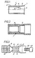
- Figure 1 shows a seamless circular cross-section metal sleeve 1 having a relatively thick wall portion 2 and a relatively thin wall portion 3.
- Such a metal sleeve can be formed by conventional metal working techniques.
- an intermediate portion 4 providing a funnel entry 5 from the portion 3 into the portion 2.
- the intermediate portion 4 also provides a shoulder 6 facing into the portion 2.
- the free end 7 of the portion 3 is flared outwardly to provide a funnel entry thereto.
- FIG 2 shows the metal sleeve 1 received in an outer sleeve 8 of electrically insulating plastics material, which outer sleeve 8 extends beyond the free end 7 of the portion 3 of the sleeve 1.
- Figure 3 shows the complete connector which includes an electrical terminal 9 having a receptacle contact end 10 for mating with a flat tab (not shown) and a crimping ferrule 11 of known form for connection to an electrical conductor, the crimping ferrule 11 being received in the portion 2 of the metal sleeve 1 with its insertion limited by the shoulder 6 therein.
- the insulation 12 is stripped from a portion at the end of an insulated electrical conductor 13, and the end portion is then inserted into the free end of the outer sleeve 8 with the end of the conductor 13 being guided into the crimping ferrule 11 by the funnel entry 5 of the metal sleeve 1, which funnel entry 5 also serves to limit insertion of the conductor by engagement of the insulation 12 on the conductor with the funnel entry 5.
- the crimping ferrule 11 is then crimped down on to the conductor 13 through the outer sleeve 8 and the portion 2 of the metal sleeve 1, and the portion 3 of the metal sleeve 1 can be crimped down on to the insulation 12 of the conductor through the outer sleeve 8, in known manner.
- the relatively thick wall of the portion 2 of the metal sleeve 1 ensures reliable crimping of the connector 1 on to the conductor 13 even when the material from which the terminal 9 is made is relatively thin as may be necessary to ensure the necessary spring properties for the receptacle end 10 thereof, while the relatively thin wall of the portion 3 of the metal sleeve 1 allows for easy crimping of this portion on to the insulation 12 of the conductor. Further, the absence of a seam in the metal sleeve 1 ensures that the metal sleeve 1 will not relax after crimping as could occur if the metal sleeve 1 had a longitudinally extending open seam as found in some known connectors.
Landscapes
- Connections Effected By Soldering, Adhesion, Or Permanent Deformation (AREA)
- Connector Housings Or Holding Contact Members (AREA)
- Coupling Device And Connection With Printed Circuit (AREA)
- Connections Arranged To Contact A Plurality Of Conductors (AREA)
- Switches With Compound Operations (AREA)
- Manufacturing Of Electrical Connectors (AREA)
Claims (4)
Applications Claiming Priority (2)
| Application Number | Priority Date | Filing Date | Title |
|---|---|---|---|
| GB911378 | 1978-03-08 | ||
| GB911378 | 1978-03-08 |
Publications (2)
| Publication Number | Publication Date |
|---|---|
| EP0004146A1 EP0004146A1 (de) | 1979-09-19 |
| EP0004146B1 true EP0004146B1 (de) | 1981-06-24 |
Family
ID=9865620
Family Applications (1)
| Application Number | Title | Priority Date | Filing Date |
|---|---|---|---|
| EP79300267A Expired EP0004146B1 (de) | 1978-03-08 | 1979-02-21 | Elektrischer Verbinder mit Presshülse |
Country Status (12)
| Country | Link |
|---|---|
| EP (1) | EP0004146B1 (de) |
| JP (1) | JPS54126989A (de) |
| AR (1) | AR215222A1 (de) |
| AT (1) | AT370259B (de) |
| BR (1) | BR7901386A (de) |
| CA (1) | CA1098601A (de) |
| DE (1) | DE2960427D1 (de) |
| DK (1) | DK147520C (de) |
| ES (1) | ES478380A1 (de) |
| FI (1) | FI67156C (de) |
| MX (1) | MX144918A (de) |
| NO (1) | NO149014C (de) |
Families Citing this family (5)
| Publication number | Priority date | Publication date | Assignee | Title |
|---|---|---|---|---|
| US4953289A (en) * | 1989-06-05 | 1990-09-04 | Pyle Overseas B.V. | Conductor terminating method |
| DE19843886A1 (de) * | 1998-09-24 | 2000-03-30 | Grote & Hartmann | Kabelschuh |
| DE19908031B4 (de) * | 1999-02-24 | 2009-08-13 | Auto-Kabel Management Gmbh | Verbindung eines elektrischen Aluminiumkabels mit einem aus Kupfer oder dergleichen Metall bestehenden Anschlußteil |
| TWI307985B (en) * | 2006-03-31 | 2009-03-21 | Ks Terminals Inc | Electrical terminal connector and method of fabricating same |
| JP6522872B2 (ja) * | 2013-02-22 | 2019-05-29 | 古河電気工業株式会社 | 圧着端子、接続構造体、コネクタ及び、接続構造体の製造方法 |
Family Cites Families (6)
| Publication number | Priority date | Publication date | Assignee | Title |
|---|---|---|---|---|
| FR925224A (fr) * | 1944-07-28 | 1947-08-28 | British Insulated Callenders | Conducteurs terminaux perfectionnés pour câbles électriques |
| GB885233A (en) * | 1957-06-04 | 1961-12-20 | Gen Electric Co Ltd | Improvements in or relating to connections between electric conductors |
| US2958723A (en) * | 1957-10-02 | 1960-11-01 | Thomas & Betts Corp | Electrical connector and sealing means therefor |
| US3356987A (en) * | 1966-08-10 | 1967-12-05 | Amp Inc | Insulation support and wire guide for an electrical connector |
| FR2048467A5 (de) * | 1969-06-09 | 1971-03-19 | Lucas Industries Ltd | |
| US3844923A (en) * | 1973-08-02 | 1974-10-29 | P Sandrock | Dangler assembly for electro-chemical installations |
-
1979
- 1979-02-12 NO NO790448A patent/NO149014C/no unknown
- 1979-02-20 CA CA321,867A patent/CA1098601A/en not_active Expired
- 1979-02-21 EP EP79300267A patent/EP0004146B1/de not_active Expired
- 1979-02-21 DE DE7979300267T patent/DE2960427D1/de not_active Expired
- 1979-02-26 AT AT0147679A patent/AT370259B/de not_active IP Right Cessation
- 1979-03-05 FI FI790742A patent/FI67156C/fi not_active IP Right Cessation
- 1979-03-05 MX MX176795A patent/MX144918A/es unknown
- 1979-03-07 DK DK94479A patent/DK147520C/da not_active IP Right Cessation
- 1979-03-07 AR AR275734A patent/AR215222A1/es active
- 1979-03-07 ES ES478380A patent/ES478380A1/es not_active Expired
- 1979-03-07 JP JP2662579A patent/JPS54126989A/ja active Pending
- 1979-03-07 BR BR7901386A patent/BR7901386A/pt unknown
Also Published As
| Publication number | Publication date |
|---|---|
| DE2960427D1 (en) | 1981-10-01 |
| AR215222A1 (es) | 1979-09-14 |
| DK94479A (da) | 1979-09-09 |
| NO149014B (no) | 1983-10-17 |
| DK147520C (da) | 1985-07-22 |
| MX144918A (es) | 1981-12-02 |
| FI67156B (fi) | 1984-09-28 |
| FI790742A7 (fi) | 1979-09-09 |
| NO790448L (no) | 1979-09-11 |
| ES478380A1 (es) | 1979-11-01 |
| JPS54126989A (en) | 1979-10-02 |
| EP0004146A1 (de) | 1979-09-19 |
| AT370259B (de) | 1983-03-10 |
| CA1098601A (en) | 1981-03-31 |
| BR7901386A (pt) | 1979-10-02 |
| NO149014C (no) | 1984-01-25 |
| ATA147679A (de) | 1982-07-15 |
| DK147520B (da) | 1984-09-10 |
| FI67156C (fi) | 1985-01-10 |
Similar Documents
| Publication | Publication Date | Title |
|---|---|---|
| US5147230A (en) | Two piece electrical female terminal | |
| EP0739059B1 (de) | Koaxialverbinder | |
| EP0122700B1 (de) | Elektrischer Koaxialverbinder für Koaxialkabel mit mehrfachem Aussenleiter | |
| EP0001159B2 (de) | Elektrischer Verbinder | |
| EP0006297B1 (de) | Fahnenartig gestalteter Endstecker | |
| US4911660A (en) | Coaxial cable angle connector | |
| EP0279508B1 (de) | Elektrische Anschlussklemme | |
| EP0000996A1 (de) | Elektrischer Verbinder | |
| US5266046A (en) | Hermaphroditic electrical connection | |
| US5135417A (en) | Dual usage electrical/electronic pin terminal system | |
| US5338233A (en) | Structure for electrically connecting a terminal and a wire | |
| US6837743B2 (en) | Cable end connector having good insulation function | |
| US12272894B2 (en) | Connector for improving transmission performance | |
| EP0043655A1 (de) | Elektrischer Anschluss mit einem Entriegelungselement | |
| US4679887A (en) | Electrical terminal | |
| EP0704110B1 (de) | Isoliertes anschlusselement mit zwei integrierten, aufgeweiteten enden der buchse | |
| WO2007089825A1 (en) | Electrical contact with wire trap | |
| US4138188A (en) | Coaxial cable plug with center conductor as center contact | |
| EP0210062B1 (de) | Elektrische Quetschverbindung | |
| EP0090538A2 (de) | Rechtwinkliger Koaxialverbinder | |
| EP0555716B1 (de) | Isolierter elektrischer Endverbinder und Herstellungsverfahren | |
| JPH0572053U (ja) | ワイヤ圧着端子 | |
| EP0004146A1 (de) | Elektrischer Verbinder mit Presshülse | |
| EP0881717A3 (de) | Elektrischer Steckverbinder | |
| EP0035861A2 (de) | Elektrischer Buchsenkontakt für das Zusammenwirken mit einem Stecker aus flachem Streifenmaterial |
Legal Events
| Date | Code | Title | Description |
|---|---|---|---|
| PUAI | Public reference made under article 153(3) epc to a published international application that has entered the european phase |
Free format text: ORIGINAL CODE: 0009012 |
|
| AK | Designated contracting states |
Designated state(s): BE CH DE FR GB IT NL SE |
|
| 17P | Request for examination filed | ||
| ITF | It: translation for a ep patent filed | ||
| GRAA | (expected) grant |
Free format text: ORIGINAL CODE: 0009210 |
|
| AK | Designated contracting states |
Designated state(s): BE CH DE FR GB IT NL SE |
|
| REF | Corresponds to: |
Ref document number: 2960427 Country of ref document: DE Date of ref document: 19811001 |
|
| PGFP | Annual fee paid to national office [announced via postgrant information from national office to epo] |
Ref country code: CH Payment date: 19930205 Year of fee payment: 15 |
|
| ITTA | It: last paid annual fee | ||
| PG25 | Lapsed in a contracting state [announced via postgrant information from national office to epo] |
Ref country code: CH Effective date: 19940228 |
|
| REG | Reference to a national code |
Ref country code: GB Ref legal event code: 732E |
|
| REG | Reference to a national code |
Ref country code: CH Ref legal event code: PL |
|
| EAL | Se: european patent in force in sweden |
Ref document number: 79300267.6 |
|
| PGFP | Annual fee paid to national office [announced via postgrant information from national office to epo] |
Ref country code: NL Payment date: 19951231 Year of fee payment: 18 |
|
| PGFP | Annual fee paid to national office [announced via postgrant information from national office to epo] |
Ref country code: SE Payment date: 19960118 Year of fee payment: 18 |
|
| PGFP | Annual fee paid to national office [announced via postgrant information from national office to epo] |
Ref country code: BE Payment date: 19960312 Year of fee payment: 18 |
|
| PG25 | Lapsed in a contracting state [announced via postgrant information from national office to epo] |
Ref country code: SE Effective date: 19970222 |
|
| PG25 | Lapsed in a contracting state [announced via postgrant information from national office to epo] |
Ref country code: BE Effective date: 19970228 |
|
| BERE | Be: lapsed |
Owner name: AMP INC. (UNE SOC. DE PENNSYLVANIE) Effective date: 19970228 |
|
| PG25 | Lapsed in a contracting state [announced via postgrant information from national office to epo] |
Ref country code: NL Effective date: 19970901 |
|
| EUG | Se: european patent has lapsed |
Ref document number: 79300267.6 |
|
| NLV4 | Nl: lapsed or anulled due to non-payment of the annual fee |
Effective date: 19970901 |
|
| PGFP | Annual fee paid to national office [announced via postgrant information from national office to epo] |
Ref country code: GB Payment date: 19980108 Year of fee payment: 20 |
|
| PGFP | Annual fee paid to national office [announced via postgrant information from national office to epo] |
Ref country code: FR Payment date: 19980209 Year of fee payment: 20 |
|
| PGFP | Annual fee paid to national office [announced via postgrant information from national office to epo] |
Ref country code: DE Payment date: 19980227 Year of fee payment: 20 |
|
| PG25 | Lapsed in a contracting state [announced via postgrant information from national office to epo] |
Ref country code: GB Free format text: LAPSE BECAUSE OF EXPIRATION OF PROTECTION Effective date: 19990220 |
|
| REG | Reference to a national code |
Ref country code: GB Ref legal event code: PE20 Effective date: 19990220 |
|
| PLBE | No opposition filed within time limit |
Free format text: ORIGINAL CODE: 0009261 |
|
| STAA | Information on the status of an ep patent application or granted ep patent |
Free format text: STATUS: NO OPPOSITION FILED WITHIN TIME LIMIT |