EP0004251A1 - Procédé d'édification d'un ouvrage portant, dispositif pour mettre en oeuvre ce procédé et jeu d'éléments pour construire le dispositif - Google Patents
Procédé d'édification d'un ouvrage portant, dispositif pour mettre en oeuvre ce procédé et jeu d'éléments pour construire le dispositif Download PDFInfo
- Publication number
- EP0004251A1 EP0004251A1 EP79810018A EP79810018A EP0004251A1 EP 0004251 A1 EP0004251 A1 EP 0004251A1 EP 79810018 A EP79810018 A EP 79810018A EP 79810018 A EP79810018 A EP 79810018A EP 0004251 A1 EP0004251 A1 EP 0004251A1
- Authority
- EP
- European Patent Office
- Prior art keywords
- girder
- support
- elements
- carrier
- formwork
- Prior art date
- Legal status (The legal status is an assumption and is not a legal conclusion. Google has not performed a legal analysis and makes no representation as to the accuracy of the status listed.)
- Withdrawn
Links
- 238000000034 method Methods 0.000 title claims abstract description 13
- 238000009415 formwork Methods 0.000 claims description 23
- 238000010276 construction Methods 0.000 claims description 17
- 238000004873 anchoring Methods 0.000 claims description 3
- 238000004519 manufacturing process Methods 0.000 claims description 2
- 230000002787 reinforcement Effects 0.000 claims 2
- 230000000284 resting effect Effects 0.000 claims 1
- 230000003014 reinforcing effect Effects 0.000 abstract description 3
- 238000009416 shuttering Methods 0.000 abstract 3
- 238000011065 in-situ storage Methods 0.000 abstract 1
- 239000002023 wood Substances 0.000 description 3
- XEEYBQQBJWHFJM-UHFFFAOYSA-N Iron Chemical compound [Fe] XEEYBQQBJWHFJM-UHFFFAOYSA-N 0.000 description 2
- 239000000463 material Substances 0.000 description 2
- 238000005452 bending Methods 0.000 description 1
- 239000012876 carrier material Substances 0.000 description 1
- 238000005266 casting Methods 0.000 description 1
- 230000002349 favourable effect Effects 0.000 description 1
- 229910052742 iron Inorganic materials 0.000 description 1
- 239000000725 suspension Substances 0.000 description 1
Images







Classifications
-
- E—FIXED CONSTRUCTIONS
- E01—CONSTRUCTION OF ROADS, RAILWAYS, OR BRIDGES
- E01D—CONSTRUCTION OF BRIDGES, ELEVATED ROADWAYS OR VIADUCTS; ASSEMBLY OF BRIDGES
- E01D21/00—Methods or apparatus specially adapted for erecting or assembling bridges
- E01D21/10—Cantilevered erection
- E01D21/105—Balanced cantilevered erection
-
- E—FIXED CONSTRUCTIONS
- E04—BUILDING
- E04G—SCAFFOLDING; FORMS; SHUTTERING; BUILDING IMPLEMENTS OR AIDS, OR THEIR USE; HANDLING BUILDING MATERIALS ON THE SITE; REPAIRING, BREAKING-UP OR OTHER WORK ON EXISTING BUILDINGS
- E04G11/00—Forms, shutterings, or falsework for making walls, floors, ceilings, or roofs
- E04G11/36—Forms, shutterings, or falsework for making walls, floors, ceilings, or roofs for floors, ceilings, or roofs of plane or curved surfaces end formpanels for floor shutterings
- E04G11/48—Supporting structures for shutterings or frames for floors or roofs
- E04G11/50—Girders, beams, or the like as supporting members for forms
Definitions
- the present invention relates to a method for producing a load-bearing structure, in particular a bridge, wherein sections of the structure are concreted in at least one formwork which is anchored to at least one existing load-bearing part of the structure itself.
- FIG. 1 A known method of this type is shown schematically in FIG. 1.
- C-shaped beams 3 are constructed to be movable symmetrically on both sides on a track and secured by means of tie rods 5.
- These beams 3 encompass the formwork space at the front, in which a section 4 of the bridge can be concreted in a formwork, not shown, which is supported on the lower leg of the beam 3. If the sections 4 are frozen, the track can ver on them lengthened and the Träoer 3 are advanced by a section length, whereupon the next section can be concreted. If the beams 3 are not to be made prohibitively large and strong, only very short sections 4, for example 3 m long, can be concreted, as shown in FIG. 2 of the drawing, and the construction progress is correspondingly slow.
- the pillar 2 must be designed with a widened head 1.
- the present invention has for its object to provide a construction method and a device by means of which a gradual construction progress by much larger section lengths is possible with simple execution and complete reusability of the carrier material.
- the solution to this problem is specified in the claims and in the subsequent description.
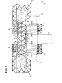
- Figure 3 shows the procedure according to the invention.
- a truss 6 made of prefabricated standardized elements is created symmetrically on both sides and anchored in the middle of the support 2 by means of tension members 7.
- a track 8 is built onto the carrier 6.
- a mobile beam 9 with rollers 10 is built thereon, which extends across the carrier 6 and consists of similar or the same prefabricated elements as the carrier 6.
- the carrier 6 consists of two Strands, on each of which a rail 8 of the track is attached.
- a formwork beam 12 which is also constructed from the same or similar elements as the beam 6 and the beam 9 and on which the formwork (not shown) for casting the bridge profile is located, is suspended by means of tie rods 11.
- a C-shaped support 14 for a work platform 15 is mounted in the middle of the beam 9, which support 14 is also made of prefabricated elements similar to or identical to those of the trusses 6, 9 and 12 exists.
- FIG. 3 shows the stage in which the first adjoining sections of the bridge profile 13 are concreted on both sides of the support 2. After concreting, the formwork must remain in place until the concrete has set sufficiently. During this time, as indicated in broken lines in FIG. 3, the beam 6 is extended further on both sides, and the track 8 is also lengthened on this beam, namely by the length of the following section 4 of the bridge. If the concrete is now set in the already concreted inner sections, it is switched off, the beams 9 with the formwork beams 12 are moved symmetrically outwards on the track 8 and secured. Now the formwork is prepared for the second sections and then the concrete is poured. With the beam 9, of course, the working platform 15 has also been moved forward, and it can be continued to be built on the carrier 6, in order to then advance another step and to concrete the next section 4.
- FIG. 4 shows how, after a certain construction progress, the girder 6 is anchored to a section 4 located further outside by means of tension members 7, while the front; effective tension members and the inner parts of the carrier 6 can be removed.
- the material released in this process is continuously used to extend the carrier 6 to the outside Ends needed.
- These processes are indicated in FIG. 4 with dash-dotted lines.
- the formwork beam 12 the beam 9 and the beam 6 can be dismantled and the material released can be used again with a different span of the bridge.
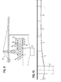
- FIGS. 9 to 11 Before further details of the construction of the devices are dealt with, the embodiment variant which is shown schematically in FIGS. 9 to 11 will be discussed. Corresponding parts are identified in the same way as in FIGS. 3 to 6.
- the support 6 is only shown on one side with a work platform in FIGS. 9 and 11, in practice it is normally worked symmetrically on both ends of the support at the same time in order to load the support 2 practically symmetrically to achieve.
- the carrier 14 carrying the work platform 15 is arranged to be movable on the track 6 of the carrier 6 by means of rollers 20, but is of course secured in every working position. It is provided with a counterweight 21.
- FIG. 9 shows the particular advantage associated with the design shown that a crane 22 can be mounted as soon as the carrier 6 and its track 8, not shown in Figure 9, have the required length.
- the mobile working platform 14, 15 allows the construction of the support 6 to be of any length because the support 14 can also be moved forward continuously on the track of the support 6 that is being created.
- the construction progress of the girder is therefore not restricted to the length of the working platform 15 during the concreting and setting of a section.
- the beam 9 is put on according to FIG. 11 and the formwork beam 12 is attached. It can now be concreted in sections in the manner described above, while the carrier 6 is continuously extended by means of the work platform 15. As FIG. 11 and FIG. 10 show the completed bridge, long sections 4 can also be created by means of suitably long formworks, thanks to the arbitrarily long pulling of the support 6 between successive concreting work.
- the crane 22 follows the construction progress. As indicated by thick and thin lines in FIG. 11, the carrier 6 can be weakened by partially removing elements within the effective anchoring 23, where it no longer has to absorb bending moments but only has to carry the crane. being the winner. Elements at the front end of the carrier 6 can be used.
- Figures 7 and 8 show, for example, the structure of the load-bearing framework from standardized elements.
- gusset plates 30 In the nodes of the trusses there are gusset plates 30 with which U-profiles 31 and 32 can be screwed to form the belt and diagonal bars and reinforcing flat profiles 33.
- the screw connection is not shown for the sake of simplicity.
- optimal combinations of standardized elements can be provided at each point to form the bars of the belt and diagonal bars of the framework.
- additional reinforcing bars 34 made of flat iron can be provided in addition to the node sheets 30, in particular for transmitting the tensile and compressive forces from one bar of the belts to the other.
- Certain nodes and / or bars of the framework can be dimensioned weaker than shown in FIGS. 7 and 8, it also being possible to provide only one gusset plate 30 to which elements 31 to 34 are screwed. On the other hand, a stronger design is also possible.
- FIG. 6 shows the design of the anchors with the tension rods 7, which are anchored to a profile 35 inserted through the openings of the bridge profile. Their upper ends are in turn connected to profiles 35a, which hold the truss 6 down. Anchors 6 are also connected to the bridge profile for laterally securing the formwork beam 12.
- FIG. 12 shows the arrangement of the rollers 20 on the beam 9 and the rails 8 on the supports 3.
- a mounting plate 40 is screwed to the belt profiles 31 of the beam 9, with which the lateral holding profiles 41 for the rollers 10 are welded.
- the rails 8 are screwed to the profiles 39, and the profiles 39 are supported on rods of the upper straps of the carrier 6 and screwed at at least one point according to FIG.
- Between nodes are counter plates 43 from below against the bars of the upper straps and are provided with holes for receiving the fastening screws for the profile 39.
- the gusset plates 30 plates 44 are screwed; which are welded to the horizontal struts 45.
- FIGS. 14 and 15 show the anchoring of the supports 6.
- the tie rods 7 are threaded at the top and can be tensioned by means of a nut 47 supported on a profile 46 by means of an axial ball bearing 48.
- the profile 46 is supported on the hold-down profile 35a, with which plates 49 with welded-on hold-down tabs 50 are screwed on.
- the hold-down tabs lie on gusset plates 30 of the lower chords of the girder 6 and thus hold down the relevant position of the girder on the wood 38 or on the bridge profile.
- a support plate 51 is inserted, which is screwed to the lower belt profiles 31.
- a plate 44 with horizontal strut 45 is also screwed to this node.
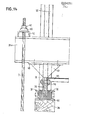
- Figure 16 finally shows the suspension of the support rods 11 for the formwork beam 12.
- the upper ends of the rods are threaded and can be tensioned or adjusted vertically by means of nuts 52, which are supported via axial ball bearings 53 on a cross profile 54, which on the Upper chord of the truss of the beam 9 rests.
- Figure 16 also shows the side Ver striving of the individual trusses of the beam 9 by means of horizontal struts 45 and their mounting plates 44th
- the counterweight 21 can be omitted and thus the load on the carrier 6 can be reduced if a track 8 made of C-profiles or I-profiles is provided, in which the rollers 20 engage laterally in a vertically secured manner.
Landscapes
- Engineering & Computer Science (AREA)
- Architecture (AREA)
- Civil Engineering (AREA)
- Structural Engineering (AREA)
- Mechanical Engineering (AREA)
- Bridges Or Land Bridges (AREA)
Applications Claiming Priority (2)
| Application Number | Priority Date | Filing Date | Title |
|---|---|---|---|
| CH213878A CH628940A5 (de) | 1978-02-28 | 1978-02-28 | Verfahren zur herstellung eines tragwerkes und einrichtung zur durchfuehrung dieses verfahrens. |
| CH2138/78 | 1978-02-28 |
Publications (1)
| Publication Number | Publication Date |
|---|---|
| EP0004251A1 true EP0004251A1 (fr) | 1979-09-19 |
Family
ID=4226753
Family Applications (1)
| Application Number | Title | Priority Date | Filing Date |
|---|---|---|---|
| EP79810018A Withdrawn EP0004251A1 (fr) | 1978-02-28 | 1979-02-27 | Procédé d'édification d'un ouvrage portant, dispositif pour mettre en oeuvre ce procédé et jeu d'éléments pour construire le dispositif |
Country Status (5)
| Country | Link |
|---|---|
| EP (1) | EP0004251A1 (fr) |
| BR (1) | BR7901191A (fr) |
| CH (1) | CH628940A5 (fr) |
| MX (1) | MX152974A (fr) |
| ZA (1) | ZA782160B (fr) |
Cited By (9)
| Publication number | Priority date | Publication date | Assignee | Title |
|---|---|---|---|---|
| WO2009043750A1 (fr) * | 2007-10-04 | 2009-04-09 | Doka Industrie Gmbh | Système de coffrage pour la construction en porte-à-faux de ponts |
| DE102007047443A1 (de) | 2007-10-04 | 2009-04-16 | Doka Industrie Gmbh | Schalungsanordnung für den Freivorbau von Brücken |
| DE102007047439A1 (de) | 2007-10-04 | 2009-04-16 | Doka Industrie Gmbh | Schalungsanrodnung für den Freivorbau von Brücken |
| CN101117791B (zh) * | 2007-08-22 | 2010-12-08 | 中铁大桥局股份有限公司 | 异型钢箱与正交异性板底模组合式移动模架及其施工方法 |
| ES2398177A1 (es) * | 2010-02-08 | 2013-03-14 | Rubrica Ingeniería Y Arquitectura, S.L. | Mejoras introducidas en un carro de avance progresivo para la construcción de puentes. |
| CN104727231A (zh) * | 2015-04-03 | 2015-06-24 | 中铁第五勘察设计院集团有限公司 | 悬臂灌注法施工连续梁及连续刚构桥几何参数结构 |
| CN111119463A (zh) * | 2020-01-06 | 2020-05-08 | 刘梓峻 | 预制梁片架设用挂篮系统 |
| CN111926720A (zh) * | 2020-08-12 | 2020-11-13 | 中建七局交通建设有限公司 | 适用于黄土地区连续钢构悬臂梁合龙的施工方法 |
| CN115491987A (zh) * | 2022-09-20 | 2022-12-20 | 四川公路桥梁建设集团有限公司 | 一种桥梁翼缘用承重支架、系统及施工方法 |
Citations (16)
| Publication number | Priority date | Publication date | Assignee | Title |
|---|---|---|---|---|
| FR698540A (fr) * | 1930-06-14 | 1931-01-31 | Louis Eilers | Procédé de construction de ponts dans lesquels, d'une façon permanente ou passagère, s'exercent des poussées ou des tractions horizontales |
| DE902188C (de) * | 1952-03-28 | 1954-01-21 | Siemens Bauunion Gmbh | Gleitschaltung fuer Betonbauten |
| US2857647A (en) * | 1955-12-01 | 1958-10-28 | Alta G Williams | Concrete forms |
| CH336183A (fr) * | 1954-10-25 | 1959-02-15 | Rogla Altet Vicente | Elément de charpente pyramidal |
| DE1263806B (de) * | 1965-05-10 | 1968-03-21 | Dyckerhoff & Widmann Ag | Verfahren zum Herstellen mehrfeldriger Brueckentragwerke aus Stahlbeton oder Spannbeton und Einrichtung hierfuer |
| FR1531277A (fr) * | 1967-07-18 | 1968-06-28 | Poutre métallique formée d'éléments assemblés pour ossatures de ponts et ouvrages similaires | |
| DE1534453A1 (de) * | 1966-03-11 | 1970-02-12 | Kunz Alfred & Co | Vorrichtung und Verfahren zur abschnittsweisen Herstellung von auf Abstuetzungen angeordneten Stahlbetontragwerken |
| DE1910197B1 (de) * | 1969-02-28 | 1970-04-23 | Dyckerhoff & Widmann Ag | Verfahren zum Herstellen von laengeren Bauwerken,insbesondere Brueckentragwerken,im abschnittsweisen Vorbau und Vorbauruestung zum Ausueben des Verfahrens |
| DE1811975A1 (de) * | 1968-11-30 | 1970-07-09 | Held & Francke Bauag | Montageruestung und Verfahren zum Herstellen von Spannbetonbruecken od.dgl. |
| DE1658631A1 (de) * | 1967-10-13 | 1970-10-29 | Strabag Bau Ag | Verfahren und Einrichtung zum Herstellen mehrfeldriger Bruecken oder dergleichen |
| CH500340A (de) * | 1966-05-18 | 1970-12-15 | Polensky & Zoellner | Verfahren und Vorrichtung zum abschnittsweisen Herstellen der Überbauten einer mehrfeldrigen Brücke aus Stahlbeton oder Spannbeton |
| DE1817776A1 (de) * | 1968-11-30 | 1971-03-04 | Held & Francke Bauag | Verfahren zur Herstellung einer Ruestung fuer Spannbetonbruecken und Ruestungstraeger zur Durchfuehrung dieses Verfahrens |
| DE1534458B1 (de) * | 1966-04-25 | 1971-05-27 | Mannesmann Leichtbau Gmbh | Einrichtung zum abschnittsweisen Herstellen des Betonueberbaus von Bruecken |
| CH541692A (de) * | 1972-07-28 | 1973-09-15 | Montan Castell Ag | Metallträger und Verwendung desselben |
| DE2258657B1 (de) * | 1972-11-30 | 1974-02-07 | Dyckerhoff & Widmann Ag | Traegerelement zum herstellen von ruesttraegern |
| DE2607805A1 (de) * | 1976-02-26 | 1977-09-01 | Dyckerhoff & Widmann Ag | Einrichtung zum abschnittsweisen freien vorbau von mehrfeldrigen brueckentragwerken aus stahl- oder spannbeton |
-
1978
- 1978-02-28 CH CH213878A patent/CH628940A5/de not_active IP Right Cessation
- 1978-04-14 ZA ZA00782160A patent/ZA782160B/xx unknown
-
1979
- 1979-02-22 BR BR7901191A patent/BR7901191A/pt unknown
- 1979-02-27 EP EP79810018A patent/EP0004251A1/fr not_active Withdrawn
- 1979-02-28 MX MX176756A patent/MX152974A/es unknown
Patent Citations (16)
| Publication number | Priority date | Publication date | Assignee | Title |
|---|---|---|---|---|
| FR698540A (fr) * | 1930-06-14 | 1931-01-31 | Louis Eilers | Procédé de construction de ponts dans lesquels, d'une façon permanente ou passagère, s'exercent des poussées ou des tractions horizontales |
| DE902188C (de) * | 1952-03-28 | 1954-01-21 | Siemens Bauunion Gmbh | Gleitschaltung fuer Betonbauten |
| CH336183A (fr) * | 1954-10-25 | 1959-02-15 | Rogla Altet Vicente | Elément de charpente pyramidal |
| US2857647A (en) * | 1955-12-01 | 1958-10-28 | Alta G Williams | Concrete forms |
| DE1263806B (de) * | 1965-05-10 | 1968-03-21 | Dyckerhoff & Widmann Ag | Verfahren zum Herstellen mehrfeldriger Brueckentragwerke aus Stahlbeton oder Spannbeton und Einrichtung hierfuer |
| DE1534453A1 (de) * | 1966-03-11 | 1970-02-12 | Kunz Alfred & Co | Vorrichtung und Verfahren zur abschnittsweisen Herstellung von auf Abstuetzungen angeordneten Stahlbetontragwerken |
| DE1534458B1 (de) * | 1966-04-25 | 1971-05-27 | Mannesmann Leichtbau Gmbh | Einrichtung zum abschnittsweisen Herstellen des Betonueberbaus von Bruecken |
| CH500340A (de) * | 1966-05-18 | 1970-12-15 | Polensky & Zoellner | Verfahren und Vorrichtung zum abschnittsweisen Herstellen der Überbauten einer mehrfeldrigen Brücke aus Stahlbeton oder Spannbeton |
| FR1531277A (fr) * | 1967-07-18 | 1968-06-28 | Poutre métallique formée d'éléments assemblés pour ossatures de ponts et ouvrages similaires | |
| DE1658631A1 (de) * | 1967-10-13 | 1970-10-29 | Strabag Bau Ag | Verfahren und Einrichtung zum Herstellen mehrfeldriger Bruecken oder dergleichen |
| DE1811975A1 (de) * | 1968-11-30 | 1970-07-09 | Held & Francke Bauag | Montageruestung und Verfahren zum Herstellen von Spannbetonbruecken od.dgl. |
| DE1817776A1 (de) * | 1968-11-30 | 1971-03-04 | Held & Francke Bauag | Verfahren zur Herstellung einer Ruestung fuer Spannbetonbruecken und Ruestungstraeger zur Durchfuehrung dieses Verfahrens |
| DE1910197B1 (de) * | 1969-02-28 | 1970-04-23 | Dyckerhoff & Widmann Ag | Verfahren zum Herstellen von laengeren Bauwerken,insbesondere Brueckentragwerken,im abschnittsweisen Vorbau und Vorbauruestung zum Ausueben des Verfahrens |
| CH541692A (de) * | 1972-07-28 | 1973-09-15 | Montan Castell Ag | Metallträger und Verwendung desselben |
| DE2258657B1 (de) * | 1972-11-30 | 1974-02-07 | Dyckerhoff & Widmann Ag | Traegerelement zum herstellen von ruesttraegern |
| DE2607805A1 (de) * | 1976-02-26 | 1977-09-01 | Dyckerhoff & Widmann Ag | Einrichtung zum abschnittsweisen freien vorbau von mehrfeldrigen brueckentragwerken aus stahl- oder spannbeton |
Non-Patent Citations (6)
| Title |
|---|
| BAUMASCHINE UND BAUTECHNIK, 17. Jarhgang, August 1970, Heft 8, Bauverlag, Wiesbaden, DE, R. SEELING: "Bauverfahren ohne Lehrger}ste f}r den Massivbr}ckenbau", Seiten 321-334. * |
| BETON UND STAHLBETONBAU, 60. Jahrgang, April 1965, Heft 4, Verlag von Wilhelm Ernst & Sohn, Berlin, DE, E. LIPPERT: "Die Bauausf}hrung der Rheinbr}cke Bendorf, Los I", Seiten 81-92. * |
| BETON UND STAHLBETONBAU, 66. Jahrgang, Oktober 1971, Heft 10, Verlag von Wilhelm Ernst & Sohn, Berlin, DE, "Freivorbau in Norwegen", Seiten XXIV, XXV. * |
| INTERNATIONAL CONSTRUCTION, 16. Jarhgang, Mai 1977, Heft 5, Verlag I.P.C. Business Press, Sutton, Surrey, GB, "Prize-winning bridge used unusual construction", Seiten 2, 3, 6, 7, 11-13. * |
| LE GENIE CIVIL, 91. Jahrgang, 13. August 1927, Verlag Le Genie Civil, Paris, FR, F. WILLM: "L' exécution de ponts en béton armé avec un cintre supérieur mobile", Seiten 173, 174. * |
| TRAVAUX, April 1974, Heft 469, Editions Science et Industrie, Paris, FR, G. QUIEDEVILLE: "Matériel approprié aux conditions de site et de délai: Le cas des ponts de Vienne", Seiten 47, 48. * |
Cited By (12)
| Publication number | Priority date | Publication date | Assignee | Title |
|---|---|---|---|---|
| CN101117791B (zh) * | 2007-08-22 | 2010-12-08 | 中铁大桥局股份有限公司 | 异型钢箱与正交异性板底模组合式移动模架及其施工方法 |
| WO2009043750A1 (fr) * | 2007-10-04 | 2009-04-09 | Doka Industrie Gmbh | Système de coffrage pour la construction en porte-à-faux de ponts |
| DE102007047443A1 (de) | 2007-10-04 | 2009-04-16 | Doka Industrie Gmbh | Schalungsanordnung für den Freivorbau von Brücken |
| DE102007047438A1 (de) | 2007-10-04 | 2009-04-16 | Doka Industrie Gmbh | Schalungsanordnung für den Freivorbau von Brücken |
| DE102007047439A1 (de) | 2007-10-04 | 2009-04-16 | Doka Industrie Gmbh | Schalungsanrodnung für den Freivorbau von Brücken |
| DE102007047438B4 (de) | 2007-10-04 | 2022-11-24 | Doka Gmbh | Schalungsanordnung für den Freivorbau von Brücken |
| ES2398177A1 (es) * | 2010-02-08 | 2013-03-14 | Rubrica Ingeniería Y Arquitectura, S.L. | Mejoras introducidas en un carro de avance progresivo para la construcción de puentes. |
| CN104727231A (zh) * | 2015-04-03 | 2015-06-24 | 中铁第五勘察设计院集团有限公司 | 悬臂灌注法施工连续梁及连续刚构桥几何参数结构 |
| CN111119463A (zh) * | 2020-01-06 | 2020-05-08 | 刘梓峻 | 预制梁片架设用挂篮系统 |
| CN111926720A (zh) * | 2020-08-12 | 2020-11-13 | 中建七局交通建设有限公司 | 适用于黄土地区连续钢构悬臂梁合龙的施工方法 |
| CN111926720B (zh) * | 2020-08-12 | 2022-01-25 | 中建七局交通建设有限公司 | 适用于黄土地区连续钢构悬臂梁合龙的施工方法 |
| CN115491987A (zh) * | 2022-09-20 | 2022-12-20 | 四川公路桥梁建设集团有限公司 | 一种桥梁翼缘用承重支架、系统及施工方法 |
Also Published As
| Publication number | Publication date |
|---|---|
| MX152974A (es) | 1986-07-11 |
| ZA782160B (en) | 1979-03-28 |
| CH628940A5 (de) | 1982-03-31 |
| BR7901191A (pt) | 1979-10-09 |
Similar Documents
| Publication | Publication Date | Title |
|---|---|---|
| EP0133850A1 (fr) | Procédé et appareil pour la construction d'un tablier de pont en béton précontraint | |
| DE1903129B2 (de) | Vorrichtung zum Anschließen eines Trägers an eine Betonstütze | |
| DE2255610A1 (de) | Schalungsgeruest fuer betonboeden | |
| DE3390026C2 (fr) | ||
| CH637443A5 (de) | Verfahren zur abschnittweisen herstellung einer ortbetonplatte und einrichtung mit einem schalboden und einem bewehrungsboden zur durchfuehrung des verfahrens. | |
| CH500340A (de) | Verfahren und Vorrichtung zum abschnittsweisen Herstellen der Überbauten einer mehrfeldrigen Brücke aus Stahlbeton oder Spannbeton | |
| EP0004251A1 (fr) | Procédé d'édification d'un ouvrage portant, dispositif pour mettre en oeuvre ce procédé et jeu d'éléments pour construire le dispositif | |
| EP0350525B1 (fr) | Procédé pour la réalisation de murs de constructions et système de coffrage | |
| AT396277B (de) | Verfahren zur errichtung von aus gussfaehigen materialien insbesondere beton bestehenden baukoerpern und vorrichtungssystem zur durchfuehrung des verfahrens | |
| AT526142A4 (de) | Verfahren zur Herstellung einer Brücke aus Längsträgern und Fahrbahnplattenelementen | |
| DE8805760U1 (de) | Verfahrbares Brücken-Arbeitsgerüst | |
| EP0471870B1 (fr) | Système de coffrage | |
| DE102007047919A1 (de) | Traggerüst und Verfahren zur Demontage und Transport | |
| DE4007222C2 (fr) | ||
| DE2759088A1 (de) | Kletterschalung zur herstellung einer geraden oder gekruemmten stahlbetonwand | |
| DE3247326A1 (de) | Verfahren und lehrgeruest zur herstellung von stahlbetonbruecken | |
| DE1659218C3 (de) | Verbundfachwerkträger sowie Verfahren zu dessen Montage | |
| EP0134823A1 (fr) | Appareil pour la construction tranche par tranche d'un tablier de pont en béton précontraint | |
| DE19607952C2 (de) | Traggerüst zur Stützung von Massivbauwerken | |
| DE3733627A1 (de) | Verfahren und vorrichtung zur gelaendeunabhaengigen abschnittweisen herstellung von spannbetonbruecken | |
| EP0056422A1 (fr) | Procédé et faux-oeuvre pour la construction de ponts en béton armé | |
| EP0133849B1 (fr) | Système de fixation d'une matrice d'impression par stencil sur un tambour d'impression | |
| AT256922B (de) | Vorrichtung zum Einschalen und Betonieren einer sich über mehrere Felder erstreckenden Brücke oder eines ähnlichen Tragwerkes | |
| DE10154236A1 (de) | Verfahren zur Herstellung einer Brücke | |
| DE2207737C2 (de) | Rüstträger zum Schalen von Stahlbeton- oder Spannbetonbrücken und ähnlichen Tragwerken mit im Grundriß gekrümmtem Überbau |
Legal Events
| Date | Code | Title | Description |
|---|---|---|---|
| PUAI | Public reference made under article 153(3) epc to a published international application that has entered the european phase |
Free format text: ORIGINAL CODE: 0009012 |
|
| AK | Designated contracting states |
Designated state(s): BE DE FR GB IT NL SE |
|
| STAA | Information on the status of an ep patent application or granted ep patent |
Free format text: STATUS: THE APPLICATION IS DEEMED TO BE WITHDRAWN |
|
| 18D | Application deemed to be withdrawn | ||
| RIN1 | Information on inventor provided before grant (corrected) |
Inventor name: FIORETTO, MAURO Inventor name: STUPNICKI, ANDRE FERNAND |