EP0056422A1 - Procédé et faux-oeuvre pour la construction de ponts en béton armé - Google Patents
Procédé et faux-oeuvre pour la construction de ponts en béton armé Download PDFInfo
- Publication number
- EP0056422A1 EP0056422A1 EP81100282A EP81100282A EP0056422A1 EP 0056422 A1 EP0056422 A1 EP 0056422A1 EP 81100282 A EP81100282 A EP 81100282A EP 81100282 A EP81100282 A EP 81100282A EP 0056422 A1 EP0056422 A1 EP 0056422A1
- Authority
- EP
- European Patent Office
- Prior art keywords
- section
- bridge
- formwork
- scaffold
- supports
- Prior art date
- Legal status (The legal status is an assumption and is not a legal conclusion. Google has not performed a legal analysis and makes no representation as to the accuracy of the status listed.)
- Withdrawn
Links
- 238000000034 method Methods 0.000 title claims abstract description 25
- 239000011150 reinforced concrete Substances 0.000 title 1
- 238000004873 anchoring Methods 0.000 claims abstract description 7
- 239000000725 suspension Substances 0.000 claims abstract description 5
- 230000000284 resting effect Effects 0.000 claims abstract description 4
- 238000009415 formwork Methods 0.000 claims description 32
- 238000010276 construction Methods 0.000 claims description 6
- 238000005520 cutting process Methods 0.000 claims description 4
- 239000011513 prestressed concrete Substances 0.000 claims description 4
- 238000004519 manufacturing process Methods 0.000 claims description 2
- 125000006850 spacer group Chemical group 0.000 claims 1
- 239000004567 concrete Substances 0.000 abstract description 10
- 238000011065 in-situ storage Methods 0.000 abstract description 2
- 238000009416 shuttering Methods 0.000 abstract 2
- 238000006073 displacement reaction Methods 0.000 description 6
- 230000036316 preload Effects 0.000 description 4
- 238000007711 solidification Methods 0.000 description 2
- 230000008023 solidification Effects 0.000 description 2
- 238000005452 bending Methods 0.000 description 1
- 238000012937 correction Methods 0.000 description 1
- 238000007665 sagging Methods 0.000 description 1
- 239000002689 soil Substances 0.000 description 1
- 230000003068 static effect Effects 0.000 description 1
- XLYOFNOQVPJJNP-UHFFFAOYSA-N water Substances O XLYOFNOQVPJJNP-UHFFFAOYSA-N 0.000 description 1
Images


Classifications
-
- E—FIXED CONSTRUCTIONS
- E01—CONSTRUCTION OF ROADS, RAILWAYS, OR BRIDGES
- E01D—CONSTRUCTION OF BRIDGES, ELEVATED ROADWAYS OR VIADUCTS; ASSEMBLY OF BRIDGES
- E01D21/00—Methods or apparatus specially adapted for erecting or assembling bridges
- E01D21/10—Cantilevered erection
-
- E—FIXED CONSTRUCTIONS
- E01—CONSTRUCTION OF ROADS, RAILWAYS, OR BRIDGES
- E01D—CONSTRUCTION OF BRIDGES, ELEVATED ROADWAYS OR VIADUCTS; ASSEMBLY OF BRIDGES
- E01D2101/00—Material constitution of bridges
- E01D2101/20—Concrete, stone or stone-like material
- E01D2101/24—Concrete
- E01D2101/26—Concrete reinforced
- E01D2101/28—Concrete reinforced prestressed
Definitions
- the invention relates to a method of the type specified in the preamble of claim 1.
- Such a method is the subject of European patent application 80100241.1.
- This method enables an economical bridge construction in the cycle method for all applications in which the bridge height is relatively low, e.g. also in the production of highways. Since the concreting takes place in in-situ concrete, a displacement of the bridge sections is avoided, which was necessary with other known cycle shifting methods (cf. DE-PS 12 37 603).
- the clock-type scaffolding used for this is fed step by step on a moving sliding track, which is always created at a low height above the ground, regardless of uneven terrain, at the same distance from the lower edge of the bridge structure.
- the auxiliary foundations only required during construction cannot always be dimensioned according to the main foundations, e.g. due to deep foundations, so that settlement-free support cannot be guaranteed for these auxiliary foundations.
- the process of concreting can be controlled in such a way that a sufficient delay in the hardening of the concrete and selection of the direction of concreting elapses a long time before the concreting process is completed, and during this time height corrections can be carried out in a plastic concrete condition.
- bias This period is generally two to three days. If unnoticed subsidence occurs during this time, additional stress can be applied to the non-prestressed concrete. This additional stress does not generally lead to the complete failure of the supporting force of the cycle shifting frame, since spring-back forces from the main beam deflection also result in upward supporting forces in this case. However, this only applies to a certain degree of settlement.
- the supporting forces from the scaffolding are reduced or redistributed in any case, and there are corresponding cutting forces in the still fresh, non-prestressed concrete.
- the extent to which these cutting forces can be absorbed by sagging probation varies from case to case.
- the invention is therefore based on the object of designing the method according to the preamble of claim 1 in such a way that the loads transferred from the teaching scaffold to the auxiliary foundations become lower or are set down at supporting points which can be controlled at a lower and better height.
- This suspension of the scaffolding on the already concrete last section of the bridge ensures that about half the concrete load and the scaffold structure over the Bridge section is transferred to the main pillar or an auxiliary support, and the scaffold supports accordingly only need to absorb about half the load. It is expedient to retract, swing out or dismantle the supports adjacent to this suspension point in order to make only the supports located in the forward direction of the load bearing effective.
- the suspension can either be articulated only to absorb transverse forces, or it can be anchored in such a way that transverse forces and bending moments can be absorbed.
- the rear support in the direction of travel can be folded up, removed or retracted.
- the invention makes it possible to use larger spans for the main scaffold girders if they are dimensioned accordingly.
- the main framework girders In the connection area to the previously concreted sections, the main framework girders only bend during concreting, but no longer in the first solidification period before prestressing.
- the front scaffold column When the front scaffold column is set, there are only slight additional stresses in any case, since the static system for this settlement load case is usually an externally supported long cantilever beam, which is very insensitive to lowering this support. In any case, no cracks will occur in the critical connection area on the section already concreted. If the outer scaffold support is subsequently set, additional pressure forces are created in the connection area on the underside of the cross-section, which is usually the most endangered cross-section point for cracks.
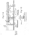
- FIG. 1A shows a part of a prestressed concrete bridge which is under construction and which, after completion, is supported on pillars 12 supported by main foundations 10 via bridge bearings 14.
- the bridge is sectionally reinforced and concreted in place using a formwork 17 carried by a scaffolding 16.
- the bridge superstructure consists of a pillar 12 resting concrete bridge sections 18 and intermediate Verbin d ungs bridge concrete sections 20. All portions which are concreted on the same formwork 17, are manufactured on einunddem sweater falsework.
- 10 auxiliary foundations 22 are erected in the ground between the main foundations, each of which has two foundation blocks 24, 26 according to the exemplary embodiments shown.
- Auxiliary supports 30 are supported on the foundation blocks 24, which support this section of the bridge superstructure after completion of a connecting section 20, as long as the connection to the bridge section 18 carried by the next bridge pier is not completed and sufficient prestressing has not yet been applied.
- the foundation blocks 26 carry a sliding track formed by rails 32, which is preferably created or built up by walking, ie only over a short length in front of and behind the cycle to be concreted.
- the scaffolding 16 can be moved on this sliding path.
- the rails 32 always run at the same distance from the lower edge of the bridge superstructure, which can be horizontal but also incline, or can have the same or different radii of curvature, in which case the formwork would have to be modified accordingly.
- the scaffolding 16 rests on hydraulic press rams 36, which are carried by roller carriages 38 and run on the rails 32 of the sliding track and opposite those supporting the formwork 17 Cross members 40 are stiffened.
- the formwork with its longitudinal beams 48 is suspended at the front end of the previously constructed bridge section 20 via anchoring means 60, so that the rear press rams 36 are relieved and can be drawn in, dismantled or folded down.
- the auxiliary supports 30 and the pillars 12 stand in the way of the free movement of the framework supporting the formwork. Special precautions must therefore be taken in the area of the auxiliary supports 30 and in the area of the pillars 12, so that the parts of the formwork or scaffolding in the cross section of the supports or the pillars are removed from the displacement path. This is done in order to ensure the overall cohesion of the scaffolding and the formwork, in sections, namely that the displacement-obstructing part between two cross members 40 is removed with these, thereby ensuring that the rigid structure by the cross members remaining in front and behind the pillar preserved.
- the construction of the bridge superstructure then takes place in sections at the point where the bridge section in question comes to rest after the completion of the bridge structure.
- the formwork in the area of the bridge supports 14 must be removed and the formwork is attached in such a way that the upper plate of the bridge bearing 14 forms part of the formwork and is aligned with the remaining part of the formwork.
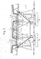
- FIG. 2 illustrate different possibilities of formwork and teaching scaffold structure for different pillar designs.
- there is only a single central support pillar 12 (which can optionally also be constructed in a resolved manner).
- the hydraulic press rams 36 can freely pass this central pillar 12 on the rails 32, and it is only necessary to ensure that the central part of the cross beams 40 and the formwork lying in the pillar area are removed.
- the cross members 40 are divided in this area into two sections 41 and 42, which are each displaceable in the direction of the arrow, the displacement can be done via spindles, hydraulic drives, rack jacks or the like ..
- the middle formwork plate 44 which lies in the area of the pillar 12, is divided in the longitudinal direction of the formwork in the longitudinal central axis and also has transverse divisions, so that the sections thus formed, as indicated by the arrows 45, can be folded down.
- the framework can be moved further by a field formed by the cross members 40, and the parts of the formwork plate 44 can then folded up again and the cross member sections 41, 42 are pushed inwards, so that again a rigid connection is ensured.
- This process is repeated step by step until the entire teaching scaffold has passed the pillar or until the scaffold has moved so far that the formwork with its center is above the pillar 12.
- auxiliary supports 30 which, as can be seen from FIG. 2, lie within the pillar cross section, so that when the formwork plate 44 is folded down, these supports can also be passed.
- the rear supports can also be easily dismantled, which is probably the simplest in practice.
- the inclined supports 50 for supporting the longitudinal beams 48 under the cantilever plates can remain firmly mounted during the entire displacement process.
- two pillars 12a and 12b are provided, along which the framework has to be moved.
- the inner foundation blocks 26 on which the running rails 32 are mounted, on which the hydraulic press rams 36 are supported or, in the retracted state, are moved over the roller carriages 38 etc.
- the auxiliary supports 30 are supported on the outer foundation block 24 and lie in the cross-sectional plane of the pillars 12a or 12b, so that it is possible to drive past both these auxiliary supports and the pillars when the corresponding parts lying in this cross section have been removed.
- the cross-member sections 41 and 42 are each displaced inward for the purpose of passing over the pillars in order to release the formwork panels 44 above the pillars 12a and 12b, which can be folded inward in the apparent manner 45.
- the scaffold inclined supports 50 which are pivoted outwards during the process, are supported on the base of the press rams 36.
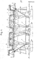
- three pillars 12c, 12d, 12e each have to be run over from the framework or the formwork.
- two frameworks 16 are provided, each running on two rails 32 of an outer or middle auxiliary foundation.
- the auxiliary supports 30 are again in the area of the cross section of the pillars and can therefore be avoided by the same precautions as the pillars themselves.
- the cross members 40 can also be displaced in sections and the corresponding formwork panels 46 are can be pivoted out of the cross-sectional area of the pillars or auxiliary supports.
- the cantilever structure is held together by longitudinal members 48, which extend over which are arranged above the cross beams 40 under the formwork 17 in a cross-sectional area which lies outside the cross-sectional area of the pillars.
- longitudinal beams 48 are connected to the hydraulic press rams 36, which in turn are stiffened in a suitable manner with one another and with the longitudinal and transverse beams.
- the cross members 40 are fixed and the sections 41 and 42 are slidably mounted.
- the scaffold For bridges according to Figure 3, which have two pillars per pillar transverse axis, the scaffold, as can be seen, consists of a central scaffold body, which rests on the rails 32, which are arranged on two separate foundations, and there are also two outer scaffold bodies which are provided by the uncouplable and inwardly displaceable cross beams are connected at a distance of one meter to three meters.
- Oblique supports 50 are articulated on the external masts and are supported on the respective roller carriages 38 via the feet of the press rams 36.
- the press rams 36 are therefore with the inclined supports 50 on the rail 32 above the foundation blocks 26.
- the hydraulic presses are retracted, so that the teaching frame is deposited on the roller carriages 38.
- the inclined supports 50 are temporarily pivoted away, so that in this state, the dead weight of the external structure is carried only by the projecting cross members 40 (in the extended state).
Landscapes
- Engineering & Computer Science (AREA)
- Architecture (AREA)
- Civil Engineering (AREA)
- Structural Engineering (AREA)
- Bridges Or Land Bridges (AREA)
Priority Applications (4)
| Application Number | Priority Date | Filing Date | Title |
|---|---|---|---|
| EP81100282A EP0056422A1 (fr) | 1981-01-15 | 1981-01-15 | Procédé et faux-oeuvre pour la construction de ponts en béton armé |
| BR8106031A BR8106031A (pt) | 1980-01-18 | 1981-01-17 | Processo e combre para a producao de pontes de concreto de aco |
| PCT/DE1981/000015 WO1981002032A1 (fr) | 1980-01-18 | 1981-01-17 | Procede et cintre pour la construction de ponts en beton arme |
| JP56500577A JPS57500654A (fr) | 1980-01-18 | 1981-01-17 |
Applications Claiming Priority (1)
| Application Number | Priority Date | Filing Date | Title |
|---|---|---|---|
| EP81100282A EP0056422A1 (fr) | 1981-01-15 | 1981-01-15 | Procédé et faux-oeuvre pour la construction de ponts en béton armé |
Publications (1)
| Publication Number | Publication Date |
|---|---|
| EP0056422A1 true EP0056422A1 (fr) | 1982-07-28 |
Family
ID=8187536
Family Applications (1)
| Application Number | Title | Priority Date | Filing Date |
|---|---|---|---|
| EP81100282A Withdrawn EP0056422A1 (fr) | 1980-01-18 | 1981-01-15 | Procédé et faux-oeuvre pour la construction de ponts en béton armé |
Country Status (1)
| Country | Link |
|---|---|
| EP (1) | EP0056422A1 (fr) |
Cited By (5)
| Publication number | Priority date | Publication date | Assignee | Title |
|---|---|---|---|---|
| DE3836568A1 (de) * | 1988-10-27 | 1990-05-03 | Reiner Dipl Ing Schweer | Lehrgeruest fuer stahlbetonbruecken fuer universellen einsatz als stationaeres und verschiebegeruest |
| ES2338618A1 (es) * | 2008-01-24 | 2010-05-10 | Sistemas Tecnicos De Encofrados Sa | Soporte para el encofrado de puentes para vias de transito. |
| CN103628411A (zh) * | 2013-11-21 | 2014-03-12 | 中交第二航务工程局有限公司 | 山区高空附塔悬臂式提梁桁吊系统 |
| CN113430959A (zh) * | 2021-08-04 | 2021-09-24 | 刘澜涛 | 延长高速公路桥梁径向宽度的施工方法 |
| CN116927095A (zh) * | 2023-08-23 | 2023-10-24 | 中铁大桥局集团第四工程有限公司 | 小半径现浇箱梁盘扣式满堂钢管支架优化搭设施工方法 |
-
1981
- 1981-01-15 EP EP81100282A patent/EP0056422A1/fr not_active Withdrawn
Non-Patent Citations (3)
| Title |
|---|
| HOCH- UND TIEFBAU, September 1977 "Jede Baustelle ist so gut wie ihr Ger}st" Seiten 17, 18 * |
| HOCH-UND TIEFBAU, November 1971 M. SCHALE "Vorfahrger}ste" Seiten 68 bis 72 * |
| SCHWEIZERISCHE BAUZEITUNG, Band 95, Nr. 41, 13. Oktober 1977 Z}rich Seiten 724 bis 726 * |
Cited By (8)
| Publication number | Priority date | Publication date | Assignee | Title |
|---|---|---|---|---|
| DE3836568A1 (de) * | 1988-10-27 | 1990-05-03 | Reiner Dipl Ing Schweer | Lehrgeruest fuer stahlbetonbruecken fuer universellen einsatz als stationaeres und verschiebegeruest |
| DE3836568C2 (de) * | 1988-10-27 | 1999-03-18 | Reiner Dipl Ing Schweer | Lehrgerüst für Stahlbetonbrücken für universellen Einsatz als stationäres und Verschiebegerüst |
| ES2338618A1 (es) * | 2008-01-24 | 2010-05-10 | Sistemas Tecnicos De Encofrados Sa | Soporte para el encofrado de puentes para vias de transito. |
| ES2338618B1 (es) * | 2008-01-24 | 2011-03-11 | Sistemas Tecnicos De Encofrados Sa | Soporte para el encofrado de puentes para vias de transito. |
| CN103628411A (zh) * | 2013-11-21 | 2014-03-12 | 中交第二航务工程局有限公司 | 山区高空附塔悬臂式提梁桁吊系统 |
| CN103628411B (zh) * | 2013-11-21 | 2015-11-18 | 中交第二航务工程局有限公司 | 山区高空附塔悬臂式提梁桁吊系统 |
| CN113430959A (zh) * | 2021-08-04 | 2021-09-24 | 刘澜涛 | 延长高速公路桥梁径向宽度的施工方法 |
| CN116927095A (zh) * | 2023-08-23 | 2023-10-24 | 中铁大桥局集团第四工程有限公司 | 小半径现浇箱梁盘扣式满堂钢管支架优化搭设施工方法 |
Similar Documents
| Publication | Publication Date | Title |
|---|---|---|
| AT396141B (de) | Brueckenwiderlager und verfahren zu seiner errichtung | |
| EP3303707B1 (fr) | Procédé de fabrication d'une dalle de tablier pour un pont | |
| DE112022001701T5 (de) | Korbförmige Stahlkastenbogenbrücke im Schwalbenstil mit großer Spannweite und speziell geformten Bogenrippen und ihre schnelle Konstruktionsmethode | |
| DE2743273B1 (de) | Verfahren zum Herstellen von langgestreckten Tragwerken,insbesondere mehrfeldrigen Brueckenueberbauten aus Stahl- oder Spannbeton | |
| WO2022256851A1 (fr) | Procédé de fabrication d'un pont à partir de poutres en pièces finies et d'éléments de plaques de chaussée | |
| DE2756255A1 (de) | Verfahren zur herstellung armierter betonbruecken und armierte betonbruecken | |
| CH500340A (de) | Verfahren und Vorrichtung zum abschnittsweisen Herstellen der Überbauten einer mehrfeldrigen Brücke aus Stahlbeton oder Spannbeton | |
| EP0032959B1 (fr) | Procédé et faux-oeuvre pour la construction de ponts en béton précontraint | |
| AT526142A4 (de) | Verfahren zur Herstellung einer Brücke aus Längsträgern und Fahrbahnplattenelementen | |
| DE3247326C2 (de) | Verfahren und Lehrgerüst zur abschnittsweisen Herstellung von Stahlbetonbrücken | |
| EP0056422A1 (fr) | Procédé et faux-oeuvre pour la construction de ponts en béton armé | |
| CH437399A (de) | Verfahren zum Herstellen von Bauwerken aus Stahl-, zum Beispiel Spannbeton, die sich hauptsächlich in einer Längsrichtung erstrecken | |
| DE2933061A1 (de) | Verfahren zum umsetzen eines geruesttraegers zur herstellung von mehrfeldrigen brueckentragwerken aus spannbeton | |
| AT298553B (de) | Einrichtung zum abschnittsweisen Herstellen eines auf Pfeilern gelagerten Bauwerkes, insbesondere einer mehrfeldrigen Brücke aus Stahlbeton oder Spannbeton | |
| DE3733627A1 (de) | Verfahren und vorrichtung zur gelaendeunabhaengigen abschnittweisen herstellung von spannbetonbruecken | |
| WO1981002032A1 (fr) | Procede et cintre pour la construction de ponts en beton arme | |
| DE2704033A1 (de) | Vorrichtung zur herstellung von mehrfeldrigen spannbetonbruecken aus fertigteilen im abschnittsweisen freivorbau | |
| DE2607574C2 (de) | Verfahren zur Herstellung von Bogentragwerken | |
| DE3203980C2 (de) | Unterführungsbauwerk sowie Verfahren zu seiner Herstellung | |
| AT344780B (de) | Spannbeton-fahrbahnplatte | |
| DE2445029C3 (de) | Verfahren zum Herstellen des Überbaus einer Brücke oder dergleichen Tragwerk aus Spannbeton sowie Stützgerüst zur Durchführung des Verfahrens | |
| AT202587B (de) | Verfahren zur Herstellung von Brücken, insbesondere Schluchtbrücken | |
| DE1220879B (de) | Unterfuehrungsbauwerk und Verfahren zu seinem nachtraeglichen Einbau | |
| DE2212898C3 (de) | Großflächige Brückenplattform aus Ortbeton und Bauverfahren zu deren Herstellung | |
| DE1234759B (de) | Verfahren zum Einschalen der einzelnen UEberbaufelder einer vielfeldrigen Bruecke |
Legal Events
| Date | Code | Title | Description |
|---|---|---|---|
| PUAI | Public reference made under article 153(3) epc to a published international application that has entered the european phase |
Free format text: ORIGINAL CODE: 0009012 |
|
| 17P | Request for examination filed |
Effective date: 19811028 |
|
| AK | Designated contracting states |
Designated state(s): AT BE CH DE FR GB IT LU NL SE |
|
| STAA | Information on the status of an ep patent application or granted ep patent |
Free format text: STATUS: THE APPLICATION HAS BEEN WITHDRAWN |
|
| 18W | Application withdrawn |
Withdrawal date: 19830301 |
|
| RIN1 | Information on inventor provided before grant (corrected) |
Inventor name: SCHWEER, RAINER, DIPL.-ING. Inventor name: STEIDLE-SAILER, MANFRED, DIPL.-ING. |