EP0004541A1 - Vis, notamment vis autotaraudeuse et machine à laminer les filets pour sa fabrication - Google Patents
Vis, notamment vis autotaraudeuse et machine à laminer les filets pour sa fabrication Download PDFInfo
- Publication number
- EP0004541A1 EP0004541A1 EP79100407A EP79100407A EP0004541A1 EP 0004541 A1 EP0004541 A1 EP 0004541A1 EP 79100407 A EP79100407 A EP 79100407A EP 79100407 A EP79100407 A EP 79100407A EP 0004541 A1 EP0004541 A1 EP 0004541A1
- Authority
- EP
- European Patent Office
- Prior art keywords
- thread
- screw
- section
- calibration
- straight
- Prior art date
- Legal status (The legal status is an assumption and is not a legal conclusion. Google has not performed a legal analysis and makes no representation as to the accuracy of the status listed.)
- Withdrawn
Links
- 238000005096 rolling process Methods 0.000 claims description 29
- 239000011295 pitch Substances 0.000 abstract 2
- 239000000463 material Substances 0.000 description 9
- 238000004519 manufacturing process Methods 0.000 description 3
- 230000015572 biosynthetic process Effects 0.000 description 2
- 238000005520 cutting process Methods 0.000 description 2
- 230000007423 decrease Effects 0.000 description 2
- 238000006073 displacement reaction Methods 0.000 description 2
- 230000000694 effects Effects 0.000 description 2
- 239000000835 fiber Substances 0.000 description 2
- 238000003754 machining Methods 0.000 description 2
- KWYUFKZDYYNOTN-UHFFFAOYSA-M Potassium hydroxide Chemical compound [OH-].[K+] KWYUFKZDYYNOTN-UHFFFAOYSA-M 0.000 description 1
- 230000002411 adverse Effects 0.000 description 1
- 238000005553 drilling Methods 0.000 description 1
- 238000005516 engineering process Methods 0.000 description 1
- 238000003780 insertion Methods 0.000 description 1
- 230000037431 insertion Effects 0.000 description 1
- WABPQHHGFIMREM-UHFFFAOYSA-N lead(0) Chemical compound [Pb] WABPQHHGFIMREM-UHFFFAOYSA-N 0.000 description 1
- 239000002184 metal Substances 0.000 description 1
- 238000000034 method Methods 0.000 description 1
- 238000000465 moulding Methods 0.000 description 1
- 229940072033 potash Drugs 0.000 description 1
- 235000015320 potassium carbonate Nutrition 0.000 description 1
- BWHMMNNQKKPAPP-UHFFFAOYSA-L potassium carbonate Substances [K+].[K+].[O-]C([O-])=O BWHMMNNQKKPAPP-UHFFFAOYSA-L 0.000 description 1
- 230000002040 relaxant effect Effects 0.000 description 1
- 230000007704 transition Effects 0.000 description 1
Images

Classifications
-
- F—MECHANICAL ENGINEERING; LIGHTING; HEATING; WEAPONS; BLASTING
- F16—ENGINEERING ELEMENTS AND UNITS; GENERAL MEASURES FOR PRODUCING AND MAINTAINING EFFECTIVE FUNCTIONING OF MACHINES OR INSTALLATIONS; THERMAL INSULATION IN GENERAL
- F16B—DEVICES FOR FASTENING OR SECURING CONSTRUCTIONAL ELEMENTS OR MACHINE PARTS TOGETHER, e.g. NAILS, BOLTS, CIRCLIPS, CLAMPS, CLIPS OR WEDGES; JOINTS OR JOINTING
- F16B25/00—Screws that cut thread in the body into which they are screwed, e.g. wood screws
- F16B25/0036—Screws that cut thread in the body into which they are screwed, e.g. wood screws characterised by geometric details of the screw
- F16B25/0042—Screws that cut thread in the body into which they are screwed, e.g. wood screws characterised by geometric details of the screw characterised by the geometry of the thread, the thread being a ridge wrapped around the shaft of the screw
- F16B25/0047—Screws that cut thread in the body into which they are screwed, e.g. wood screws characterised by geometric details of the screw characterised by the geometry of the thread, the thread being a ridge wrapped around the shaft of the screw the ridge being characterised by its cross-section in the plane of the shaft axis
-
- B—PERFORMING OPERATIONS; TRANSPORTING
- B21—MECHANICAL METAL-WORKING WITHOUT ESSENTIALLY REMOVING MATERIAL; PUNCHING METAL
- B21H—MAKING PARTICULAR METAL OBJECTS BY ROLLING, e.g. SCREWS, WHEELS, RINGS, BARRELS, BALLS
- B21H3/00—Making helical bodies or bodies having parts of helical shape
- B21H3/02—Making helical bodies or bodies having parts of helical shape external screw-threads ; Making dies for thread rolling
- B21H3/027—Rolling of self-tapping screws
-
- F—MECHANICAL ENGINEERING; LIGHTING; HEATING; WEAPONS; BLASTING
- F16—ENGINEERING ELEMENTS AND UNITS; GENERAL MEASURES FOR PRODUCING AND MAINTAINING EFFECTIVE FUNCTIONING OF MACHINES OR INSTALLATIONS; THERMAL INSULATION IN GENERAL
- F16B—DEVICES FOR FASTENING OR SECURING CONSTRUCTIONAL ELEMENTS OR MACHINE PARTS TOGETHER, e.g. NAILS, BOLTS, CIRCLIPS, CLAMPS, CLIPS OR WEDGES; JOINTS OR JOINTING
- F16B25/00—Screws that cut thread in the body into which they are screwed, e.g. wood screws
- F16B25/001—Screws that cut thread in the body into which they are screwed, e.g. wood screws characterised by the material of the body into which the screw is screwed
- F16B25/0031—Screws that cut thread in the body into which they are screwed, e.g. wood screws characterised by the material of the body into which the screw is screwed the screw being designed to be screwed into different materials, e.g. a layered structure or through metallic and wooden parts
-
- F—MECHANICAL ENGINEERING; LIGHTING; HEATING; WEAPONS; BLASTING
- F16—ENGINEERING ELEMENTS AND UNITS; GENERAL MEASURES FOR PRODUCING AND MAINTAINING EFFECTIVE FUNCTIONING OF MACHINES OR INSTALLATIONS; THERMAL INSULATION IN GENERAL
- F16B—DEVICES FOR FASTENING OR SECURING CONSTRUCTIONAL ELEMENTS OR MACHINE PARTS TOGETHER, e.g. NAILS, BOLTS, CIRCLIPS, CLAMPS, CLIPS OR WEDGES; JOINTS OR JOINTING
- F16B41/00—Measures against loss of bolts, nuts, or pins; Measures against unauthorised operation of bolts, nuts or pins
- F16B41/002—Measures against loss of bolts, nuts or pins
Definitions
- the invention relates to a screw, in particular a thread forming screw, with at least one straight threaded shaft section and at least one calibration section, which extends over one or more thread turns, the outside diameter of the calibration section being larger than the outside diameter of the straight threaded section.
- a threaded form screw is known, the cross section of which has the shape of a three-sided constant thickness over the entire shaft length with three rounded edges and intermediate, radially recessed sides.
- the face of the screw is tapered to facilitate insertion into the hole.
- the fiber course is redirected during thread forming and the material is cold hardened. This ensures a high strength of the connection with a high load-bearing thread coverage over the entire screw-in length. The screw is snug and the load is evenly transferred to the internal thread.
- the thread-forming screw permanently deforms the workpiece into which it is screwed.
- workpieces made of metal or plastic are somewhat elastic within the limits given by the material properties and the material of the workpiece tends to re-form within the elastic limits, i.e. to a small extent return to its original state when the molding pressure ceases.
- the relaxing springback is also determined by the geometrical shape of the workpiece into which the screw was screwed. Given the large number of influencing variables, it is not possible to precisely predict the type of internal springback. In any case, after the thread formation is completed, the springback creates radial and axial compressive and frictional forces, which cause relatively high torques even after the screw tip may have emerged on the back of the workpiece.
- the thread-forming screw has a very low torque for further screwing in after the screw tip has emerged from a through hole.
- a typical example of such an application is an electrical connection screw.
- the electrical connection screw must be a screw with a low torque, in which the permissible tightening torque can be used as far as possible to generate a high clamping force of the electrical lead wire, instead of only overcoming frictional resistance when the screw is screwed into the workpiece.
- Thread-forming screws are already known in which a thread-forming section is arranged in the region of the screw tip.
- the rear threads of the screw shaft sit with more or less precisely defined play in the internal thread created by the thread-forming section.
- the friction between the workpiece and the rear shaft section is substantially ver wrestles without adversely affecting the other properties of the screw connection, especially the connection strength.
- a screw with a polygonal cross section is known from US Pat. No. 3,875,780, in which one or more calibration threads with a larger thread outer diameter are produced by reducing the flank angle of the calibration threads in the area from the flank diameter in the direction of the thread tip by means of a suitable rolling jaw. The area between the flank diameter and the thread core diameter is not changed.
- the calibration thread section must lie in the area of the screw tip, and the shape of the calibration thread is inaccurate, so that the internal thread also does not have a precisely defined shape.
- the additional material for the calibration runs is obtained by compressing the screw tip.
- Such a threaded section with an alternating thread pitch could be attached to a thread-forming screw in order to produce an internal thread.
- the normal threads of the remaining screw shank could then run with play in the preformed internal thread.
- the disadvantage of this arrangement is the length of expansion on the screw shaft, which must extend over several threads and thus make many technical applications impossible.
- the object of the invention is now to avoid the disadvantages of the known screws with a calibration section.
- the screw can be both a thread shape and a locking screw.
- a thread-forming screw regardless of the type of thread, the screw is caused in the shaped internal thread of a through hole with a very low torque ment is running and cannot be shaken out of this internal thread by vibration.
- the screw can be screwed into blind holes with torques that hardly change with increasing screwing depth.
- the calibration section lends the screw a vibration protection at a precisely predetermined point.
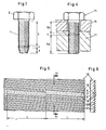
- the shaft 1 consists of a threaded shaft 1 and a hexagon screw head 2.
- the shaft 1 is divided into a tip section 3, a calibration section 4 and a straight section 5.
- the tip section 3 is tapered to insert the shaft into to facilitate the drilling of a workpiece.
- the actual formation of the internal thread in the wall of the bore is carried out by the calibration section 4, which is arranged approximately in the region of the third to fifth thread.
- the straight threaded shaft section 5 adjoining the calibration section 4 runs with little friction in the preformed internal thread.
- FIG. 2 shows a further embodiment of a thread-forming screw.
- the calibration section 4 is arranged between two straight section pieces 5a and 5b.
- the screw threads for example of a standardized metric thread profile, are indicated by the dashed line 6.
- the outside diameter D of the calibration section 4 is larger than the outside diameter D 0 of the adjacent straight shaft sections Sa and 5b.
- Compensation grooves 8 are arranged on both sides of the raised calibration thread 7, which lie deeper than the corresponding grooves 9 of the straight shaft sections 5a, 5b.
- the compensating grooves 8 are also deeper than the grooves 10 of the standard screw indicated by dashed lines.
- the thread core diameter d 0 of the straight shaft sections 5a, 5b is thus somewhat larger than the thread core diameter d 1 of the potash section 4.
- the thread flank angle ⁇ is the same for the straight threaded shank sections and for the calibration section. On the other hand, there are minor fluctuations in the thread pitch in the transition area between the regular thread turns and the calibration thread turn.
- the raised tooth of the calibration thread 7 is wider in the entire thread flank area than the teeth of the regular threads of the straight shaft sections.
- the tooth base or the distance m l of the two compensating grooves 8 is also wider than the corresponding distance m 0 for the straight sections.
- the calibration section 4 can be located at any point on the screw thread shaft 1, that is, depending on the practical application, in the vicinity of the screw tip, the screw head or the shaft center.
- the workpiece material displaced by the calibration thread 7 is plastically deformed and flows into the compensating grooves on both sides of the raised calibration thread tooth.
- the required screw torque is influenced only by part 5a of the screw shaft in front of the calibration section and by this itself, but not by the following section 5b (Fig. 2).
- a calibration section arranged in the area of the screw tip can e.g. serve as a captive device for the screw. If the screw is unscrewed from the workpiece, a noticeable increase in torque occurs at the moment the calibration section re-enters the back of the workpiece.
- the effect of the calibration section as thread locking is not limited to thread form screws.
- the calibration section can also be attached to screw threads that are screwed into cut internal threads at a desired location (Fig. 4).
- the screw can be given a vibration resistance in an exactly predetermined screw-in position. Up to this position, in contrast to other known screws with increased threads over the entire screw shaft length, it can be screwed in with a torque of almost zero. There is no danger that the cut internal thread grooves will be rubbed out during the assembly process by thread increases and widenings at screw thread points, where they are not necessary at all due to the screw connection, and thus the securing effect will decrease.
- Fig. 4 the workpiece is designated 11 and the locking screw 14.
- the part 15 clamped by the screw can be an electrical connection.
- the thread play e is present in area 5a, while the screw is snugly seated in area 4.
- Screw shanks with one or more calibration sections can be produced by machining or better by a thread rolling process known per se. It is of no importance to the invention whether the cross section of the blank is circular or, as is often the case with thread-forming screws, is polygonally unequal or polygonally the same thickness.
- a section of a thread rolling tool 16 is shown in a top view or in cross section.
- the roller jaw zone responsible for producing the calibration thread 7 has at least one deep roller jaw groove 18 in the region 17, the shape of which is the negative of the increased thread 7. Adjacent to this deep groove 18 are one or two raised rolling jaw profiles 19, the shape of which corresponds to the negative of the compensating grooves 8. In Fig. 5, the deep groove 18 is drawn in dashed lines, and the raised profiles 19 are dotted.
- the remaining rolling jaw grooves 20 outside the calibrating rolling jaw zone 17 are less deep or the rolling jaw profiles 21 are less high than the aforementioned grooves 18 and profiles 19 in the calibration zone.
- the rolling jaw can be produced, for example, in such a way that, starting from a rolling jaw with uniform grooves and profiles, the rolling jaw grooves 18 dashed in FIG. 5 are worked to a depth of approximately 10% with a machining tool that corresponds to the profile of the rolling jaw groove 20 and all rolled profiles 21, with the exception of the calibration profiles 19, are processed to a height which is approximately 10% lower.
- the rolling jaw calibration area offers the possibility of rolling this area on at any point on the screw shank and, by means of additional radial material displacement or the calibration thread turns on the screw shank: to ensure that the screw performs its function safely and precisely can perform.
- the length L of the calibration range repeated on the rolling jaw is at least the same, better somewhat longer than the length of a complete revolution of a screw on the rolling jaw.
Landscapes
- Engineering & Computer Science (AREA)
- General Engineering & Computer Science (AREA)
- Mechanical Engineering (AREA)
- Physics & Mathematics (AREA)
- Geometry (AREA)
- Forging (AREA)
Applications Claiming Priority (2)
| Application Number | Priority Date | Filing Date | Title |
|---|---|---|---|
| CH1774/78 | 1978-02-17 | ||
| CH177478 | 1978-02-17 |
Publications (1)
| Publication Number | Publication Date |
|---|---|
| EP0004541A1 true EP0004541A1 (fr) | 1979-10-17 |
Family
ID=4218289
Family Applications (1)
| Application Number | Title | Priority Date | Filing Date |
|---|---|---|---|
| EP79100407A Withdrawn EP0004541A1 (fr) | 1978-02-17 | 1979-02-12 | Vis, notamment vis autotaraudeuse et machine à laminer les filets pour sa fabrication |
Country Status (1)
| Country | Link |
|---|---|
| EP (1) | EP0004541A1 (fr) |
Cited By (5)
| Publication number | Priority date | Publication date | Assignee | Title |
|---|---|---|---|---|
| WO2002098739A1 (fr) | 2001-06-05 | 2002-12-12 | Hensen Packaging Concept Gmbh | Dispositif et procede pour l'ouverture de sachets vides |
| EP1564422A1 (fr) * | 2004-02-14 | 2005-08-17 | LuK Lamellen und Kupplungsbau Beteiligungs KG | Procédé et vis pour relier deux unités de construction d'un embrayage de frottement |
| EP1898402A1 (fr) * | 2001-09-11 | 2008-03-12 | Matsushita Electric Industrial Co., Ltd. | Appareil à disque optique |
| EP1965087A3 (fr) * | 2007-02-28 | 2009-11-11 | Baier & Michels GMBH und CO. KG. | Vis dotée d'un filetage formant un filetage, ébauche de fabrication de la vis et raccordement de vis |
| CN103348147A (zh) * | 2010-11-29 | 2013-10-09 | 鲁艾亚全球扣具股份公司 | 自锁螺母 |
Citations (14)
| Publication number | Priority date | Publication date | Assignee | Title |
|---|---|---|---|---|
| US2269476A (en) * | 1941-01-21 | 1942-01-13 | Illinois Tool Works | Self-locking screw |
| US2352540A (en) * | 1942-01-12 | 1944-06-27 | Illinois Tool Works | Self-locking screw |
| US2829696A (en) * | 1955-11-23 | 1958-04-08 | Illinois Tool Works | Screw for preassembly with workpieces |
| FR1343518A (fr) * | 1962-06-07 | 1963-11-22 | Procédé pour obtenir un auto-serrage d'un écrou sur une vis | |
| CH386182A (fr) * | 1961-06-27 | 1964-12-31 | Res Eng & Mfg | Vis à filet auto-taraudant et procédé de fabrication de cette vis |
| US3381733A (en) * | 1966-07-01 | 1968-05-07 | Glenn W. Stanwick | Thread form |
| DE1920693A1 (de) * | 1968-04-25 | 1970-07-16 | Jllinois Tool Works Inc | Schraube sowie Verfahren und Vorrichtung zur Herstellung derselben |
| DE2157373A1 (de) * | 1970-11-23 | 1972-05-25 | Textron Inc | Selbsthaltendes Befestigungselement und Werkzeug zu seiner Herstellung |
| US3875780A (en) * | 1974-01-03 | 1975-04-08 | Rockford Headed Products | Method of making a thread forming screw |
| DE2461546A1 (de) * | 1974-01-03 | 1975-07-17 | Rockford Headed Products | Gewindeformende schraube |
| US3939512A (en) * | 1967-09-23 | 1976-02-24 | Walter Thurston | Male screw-forming members |
| US3972084A (en) * | 1973-04-23 | 1976-08-03 | Litton Fastening Systems | Fastener manufacturing method |
| DE2365132B2 (de) * | 1973-12-17 | 1977-02-17 | Keystone Consolidated Industries Inc., (n.d.Ges.d. Staates Delaware, Peoria, 111. (V.StA.) | Sicherungsschraube |
| DE2702538A1 (de) * | 1976-01-23 | 1977-08-11 | Aackersberg Mortensen | Schraube, mutter oder sonstiger gegenstand mit einem gewindetragenden teil |
-
1979
- 1979-02-12 EP EP79100407A patent/EP0004541A1/fr not_active Withdrawn
Patent Citations (14)
| Publication number | Priority date | Publication date | Assignee | Title |
|---|---|---|---|---|
| US2269476A (en) * | 1941-01-21 | 1942-01-13 | Illinois Tool Works | Self-locking screw |
| US2352540A (en) * | 1942-01-12 | 1944-06-27 | Illinois Tool Works | Self-locking screw |
| US2829696A (en) * | 1955-11-23 | 1958-04-08 | Illinois Tool Works | Screw for preassembly with workpieces |
| CH386182A (fr) * | 1961-06-27 | 1964-12-31 | Res Eng & Mfg | Vis à filet auto-taraudant et procédé de fabrication de cette vis |
| FR1343518A (fr) * | 1962-06-07 | 1963-11-22 | Procédé pour obtenir un auto-serrage d'un écrou sur une vis | |
| US3381733A (en) * | 1966-07-01 | 1968-05-07 | Glenn W. Stanwick | Thread form |
| US3939512A (en) * | 1967-09-23 | 1976-02-24 | Walter Thurston | Male screw-forming members |
| DE1920693A1 (de) * | 1968-04-25 | 1970-07-16 | Jllinois Tool Works Inc | Schraube sowie Verfahren und Vorrichtung zur Herstellung derselben |
| DE2157373A1 (de) * | 1970-11-23 | 1972-05-25 | Textron Inc | Selbsthaltendes Befestigungselement und Werkzeug zu seiner Herstellung |
| US3972084A (en) * | 1973-04-23 | 1976-08-03 | Litton Fastening Systems | Fastener manufacturing method |
| DE2365132B2 (de) * | 1973-12-17 | 1977-02-17 | Keystone Consolidated Industries Inc., (n.d.Ges.d. Staates Delaware, Peoria, 111. (V.StA.) | Sicherungsschraube |
| US3875780A (en) * | 1974-01-03 | 1975-04-08 | Rockford Headed Products | Method of making a thread forming screw |
| DE2461546A1 (de) * | 1974-01-03 | 1975-07-17 | Rockford Headed Products | Gewindeformende schraube |
| DE2702538A1 (de) * | 1976-01-23 | 1977-08-11 | Aackersberg Mortensen | Schraube, mutter oder sonstiger gegenstand mit einem gewindetragenden teil |
Cited By (5)
| Publication number | Priority date | Publication date | Assignee | Title |
|---|---|---|---|---|
| WO2002098739A1 (fr) | 2001-06-05 | 2002-12-12 | Hensen Packaging Concept Gmbh | Dispositif et procede pour l'ouverture de sachets vides |
| EP1898402A1 (fr) * | 2001-09-11 | 2008-03-12 | Matsushita Electric Industrial Co., Ltd. | Appareil à disque optique |
| EP1564422A1 (fr) * | 2004-02-14 | 2005-08-17 | LuK Lamellen und Kupplungsbau Beteiligungs KG | Procédé et vis pour relier deux unités de construction d'un embrayage de frottement |
| EP1965087A3 (fr) * | 2007-02-28 | 2009-11-11 | Baier & Michels GMBH und CO. KG. | Vis dotée d'un filetage formant un filetage, ébauche de fabrication de la vis et raccordement de vis |
| CN103348147A (zh) * | 2010-11-29 | 2013-10-09 | 鲁艾亚全球扣具股份公司 | 自锁螺母 |
Similar Documents
| Publication | Publication Date | Title |
|---|---|---|
| DE4333791C2 (de) | Gewindeschneidschraube | |
| DE3610392C2 (de) | Schraube für verunreinigte Gewindebohrungen | |
| DE2544531C2 (de) | Gewindeselbstschneidende Schraube | |
| DE1400883B1 (de) | Spanlos gewindeherstellende Schraube | |
| DE60211920T2 (de) | Selbstschneidende schraube, verfahren und werkzeuge zum herstellen derselben sowie verfahren zum verbinden von dünnen werkstücken | |
| DE69918078T2 (de) | Selbstfurchende schraube und rohling dafür | |
| DE2461546A1 (de) | Gewindeformende schraube | |
| DE2461536A1 (de) | Gewindeformende schraube und verfahren zu ihrer herstellung | |
| AT212249B (de) | Kaltgezogener Draht mit von der Kreisform abweichendem Massivquerschnitt sowie Verfahren und Vorrichtung zu seiner Herstellung | |
| EP3719330B1 (fr) | Vis avec une discontinuité sur une section de filetage intermédiaire | |
| DE1750617A1 (de) | Befestigungsmittel und Verfahren zu seiner Herstellung | |
| EP1616652A2 (fr) | Outil pour le finissage sans enlèvement de copeaux d'un taraudage préformé, procédé de fabrication de cet outil et procéde de réalisation d'un taraudage | |
| DE102013203151A1 (de) | Betonschraube | |
| EP0408492B1 (fr) | Ecrou avec filetage | |
| DE4444467A1 (de) | Gewindeschneidschraube | |
| DE3050448C2 (fr) | ||
| DE69209601T2 (de) | Gewindebildungsmethode und Gerät | |
| EP3374649B1 (fr) | Vis autotaraudeuse | |
| EP1891341B1 (fr) | Boulon creux pourvu d'un alésage longitudinal et sa méthode de fabrication | |
| DE3804291C2 (fr) | ||
| EP0504782B1 (fr) | Vis, procédé et matrice de laminage pour sa fabrication | |
| EP0292734B1 (fr) | Vis formant des filets | |
| DE1813758A1 (de) | Selbsthemmende Schraubenmutter | |
| DE1750206A1 (de) | Hemmunsschraube und Verfahren fuer ihre Herstellung | |
| DE2157373A1 (de) | Selbsthaltendes Befestigungselement und Werkzeug zu seiner Herstellung |
Legal Events
| Date | Code | Title | Description |
|---|---|---|---|
| PUAI | Public reference made under article 153(3) epc to a published international application that has entered the european phase |
Free format text: ORIGINAL CODE: 0009012 |
|
| AK | Designated contracting states |
Designated state(s): BE CH DE FR GB IT LU NL SE |
|
| STAA | Information on the status of an ep patent application or granted ep patent |
Free format text: STATUS: THE APPLICATION IS DEEMED TO BE WITHDRAWN |
|
| 18D | Application deemed to be withdrawn | ||
| RIN1 | Information on inventor provided before grant (corrected) |
Inventor name: MUFF, ANTON Inventor name: BERSET, JEAN-LOUIS Inventor name: MAYER, HERMANN Inventor name: FELDMANN, ALBERT |