EP1564422A1 - Procédé et vis pour relier deux unités de construction d'un embrayage de frottement - Google Patents
Procédé et vis pour relier deux unités de construction d'un embrayage de frottement Download PDFInfo
- Publication number
- EP1564422A1 EP1564422A1 EP05002010A EP05002010A EP1564422A1 EP 1564422 A1 EP1564422 A1 EP 1564422A1 EP 05002010 A EP05002010 A EP 05002010A EP 05002010 A EP05002010 A EP 05002010A EP 1564422 A1 EP1564422 A1 EP 1564422A1
- Authority
- EP
- European Patent Office
- Prior art keywords
- screw
- thread
- cast
- screw connection
- screws
- Prior art date
- Legal status (The legal status is an assumption and is not a legal conclusion. Google has not performed a legal analysis and makes no representation as to the accuracy of the status listed.)
- Granted
Links
- 238000000034 method Methods 0.000 title claims abstract description 13
- 230000008878 coupling Effects 0.000 title description 3
- 238000010168 coupling process Methods 0.000 title description 3
- 238000005859 coupling reaction Methods 0.000 title description 3
- 238000010276 construction Methods 0.000 title 1
- 239000000463 material Substances 0.000 claims abstract description 19
- 229910001018 Cast iron Inorganic materials 0.000 claims abstract description 11
- 239000012188 paraffin wax Substances 0.000 claims abstract description 8
- 238000006073 displacement reaction Methods 0.000 claims abstract description 6
- OKTJSMMVPCPJKN-UHFFFAOYSA-N Carbon Chemical compound [C] OKTJSMMVPCPJKN-UHFFFAOYSA-N 0.000 claims description 9
- 239000000314 lubricant Substances 0.000 claims description 8
- 230000005540 biological transmission Effects 0.000 claims description 6
- 239000011248 coating agent Substances 0.000 claims description 6
- 229910002804 graphite Inorganic materials 0.000 claims description 6
- 239000010439 graphite Substances 0.000 claims description 6
- 238000005266 casting Methods 0.000 claims description 5
- 238000000576 coating method Methods 0.000 claims description 5
- 238000002485 combustion reaction Methods 0.000 claims description 4
- 230000015572 biosynthetic process Effects 0.000 claims description 3
- 229910001060 Gray iron Inorganic materials 0.000 claims description 2
- 238000010079 rubber tapping Methods 0.000 claims description 2
- 238000001125 extrusion Methods 0.000 claims 1
- 230000008569 process Effects 0.000 abstract description 2
- 238000013461 design Methods 0.000 description 6
- 238000004519 manufacturing process Methods 0.000 description 6
- 238000005520 cutting process Methods 0.000 description 3
- 238000004146 energy storage Methods 0.000 description 3
- 230000008901 benefit Effects 0.000 description 2
- 230000009977 dual effect Effects 0.000 description 2
- 238000003780 insertion Methods 0.000 description 2
- 230000037431 insertion Effects 0.000 description 2
- 230000001050 lubricating effect Effects 0.000 description 2
- 230000009471 action Effects 0.000 description 1
- 239000000853 adhesive Substances 0.000 description 1
- 230000001070 adhesive effect Effects 0.000 description 1
- 239000003153 chemical reaction reagent Substances 0.000 description 1
- 239000003795 chemical substances by application Substances 0.000 description 1
- 150000001875 compounds Chemical class 0.000 description 1
- 230000006835 compression Effects 0.000 description 1
- 238000007906 compression Methods 0.000 description 1
- 238000011161 development Methods 0.000 description 1
- 230000018109 developmental process Effects 0.000 description 1
- 238000007598 dipping method Methods 0.000 description 1
- 238000005553 drilling Methods 0.000 description 1
- 239000004519 grease Substances 0.000 description 1
- 230000009931 harmful effect Effects 0.000 description 1
- 238000003754 machining Methods 0.000 description 1
- 239000003094 microcapsule Substances 0.000 description 1
- 238000005457 optimization Methods 0.000 description 1
- 238000012545 processing Methods 0.000 description 1
- 230000009467 reduction Effects 0.000 description 1
- 239000000565 sealant Substances 0.000 description 1
- 238000003860 storage Methods 0.000 description 1
- 239000000725 suspension Substances 0.000 description 1
- 239000002966 varnish Substances 0.000 description 1
Images
Classifications
-
- F—MECHANICAL ENGINEERING; LIGHTING; HEATING; WEAPONS; BLASTING
- F16—ENGINEERING ELEMENTS AND UNITS; GENERAL MEASURES FOR PRODUCING AND MAINTAINING EFFECTIVE FUNCTIONING OF MACHINES OR INSTALLATIONS; THERMAL INSULATION IN GENERAL
- F16B—DEVICES FOR FASTENING OR SECURING CONSTRUCTIONAL ELEMENTS OR MACHINE PARTS TOGETHER, e.g. NAILS, BOLTS, CIRCLIPS, CLAMPS, CLIPS OR WEDGES; JOINTS OR JOINTING
- F16B37/00—Nuts or like thread-engaging members
- F16B37/005—Nuts or like thread-engaging members into which threads are cut during screwing
-
- F—MECHANICAL ENGINEERING; LIGHTING; HEATING; WEAPONS; BLASTING
- F16—ENGINEERING ELEMENTS AND UNITS; GENERAL MEASURES FOR PRODUCING AND MAINTAINING EFFECTIVE FUNCTIONING OF MACHINES OR INSTALLATIONS; THERMAL INSULATION IN GENERAL
- F16B—DEVICES FOR FASTENING OR SECURING CONSTRUCTIONAL ELEMENTS OR MACHINE PARTS TOGETHER, e.g. NAILS, BOLTS, CIRCLIPS, CLAMPS, CLIPS OR WEDGES; JOINTS OR JOINTING
- F16B33/00—Features common to bolt and nut
- F16B33/06—Surface treatment of parts furnished with screw-thread, e.g. for preventing seizure or fretting
-
- F—MECHANICAL ENGINEERING; LIGHTING; HEATING; WEAPONS; BLASTING
- F16—ENGINEERING ELEMENTS AND UNITS; GENERAL MEASURES FOR PRODUCING AND MAINTAINING EFFECTIVE FUNCTIONING OF MACHINES OR INSTALLATIONS; THERMAL INSULATION IN GENERAL
- F16B—DEVICES FOR FASTENING OR SECURING CONSTRUCTIONAL ELEMENTS OR MACHINE PARTS TOGETHER, e.g. NAILS, BOLTS, CIRCLIPS, CLAMPS, CLIPS OR WEDGES; JOINTS OR JOINTING
- F16B25/00—Screws that cut thread in the body into which they are screwed, e.g. wood screws
Definitions
- the invention relates to a screw connection between two components, wherein one of the components made of cast iron material.
- the present invention has the object, screw of the above mentioned type such that they in a particularly simple and cost-effective manner and are producible. It should also by appropriate design of the screw and optimization of the procedure for producing such screw connections their use in mass production are facilitated. By the invention should also simplify the production and design of the cast component to be joined are, including the use of tools and the processing costs for the production such cast components to be reduced.
- this is achieved in that the individual screw by means of a screw formed when screwing into the originally thread-free Verschraubungsaus originallyung the cast component the screw thread by casting material displacement forms. It is therefore not according to the invention, the thread in the casting material cut, ie machined, but the formation of the threads is done by material flow, ie displacement of the casting material. Such a design has the advantage that the threads thus produced have a high strength. For many applications may need additional means to secure the screws inside the threaded hole be waived.
- a threaded end which is frusto-conical, wherein the cone angle in the order of between 10 ° and 20 °, preferably between 14 ° and may be 17 °.
- a frustoconical design of the screw end allows a simple threading and an initial good fit in the recess. This also ensures a stable side guidance, so that tilting during insertion the screw can be avoided. This is especially true of an automated one Assembly of advantage.
- the receiving recess may also be expedient if the receiving recess a Einfädelungsschräge having. For some applications, it may be useful if the receiving recess over a small length range a slightly larger diameter has as the remaining areas of the recess. This can be done for example by a stepped recess can be ensured.
- the original diameter of a EinschraubausNeillung 85% to 95%, preferably 88% to 93% of the outer thread diameter of the screw exhibit.
- a lubricant or lubricant is used. Such an agent may shortly before or during screwing be supplied. According to the invention, however, it is particularly advantageous if screws be used, which in advance at least partially with a screwing the Screws and forming the screw thread-enhancing coating provided are. Particularly advantageous is the use of screws has proven that at least in End portion of their thread are coated with paraffin. But instead of paraffin can also other lubricants or lubricants are used, such as. B. fat. Alternatively, too Adhesive or sealant find use, which initially a sliding or lubricating function can take over and harden only afterwards. Such properties can ensured for example by microcapsules within the coating agent used which are destroyed when screwed, thereby releasing a reagent becomes.
- At least the threaded portion of the screws has a high hardness
- the latter can be achieved, for example, by use of case-hardened screws or be guaranteed by tempered screws.
- Such screws can For example, inductively hardened thread forming zones have.
- the cast component may consist of gray cast iron.
- the cast iron with vermicular graphite (GGV) or nodular graphite (GGG) or lamellar graphite (GGL) is used.
- GGV 30 can be used.
- the inventively designed screw can be particularly advantageous Be used in torque transmission devices, which between a Internal combustion engine and a downstream transmission can be used.
- the cast component can advantageously the counter-pressure plate of a clutch unit form on the means of the thread-forming or thread-forming screws the housing of a friction clutch is attached.
- This counterpressure plate can be the secondary mass form a so-called dual mass flywheel.
- Corresponding clutch units or dual-mass flywheels are for example DE 197 27 678 C2, DE 195 06 157 A1, DE 100 58 884 A1 or DE 37 21 712 A1 known.
- the invention further relates to a method for forming a screw connection between at least two components, one of which is made of cast iron material, wherein the cast component is provided with Verschraubungsaus fundamentallessness that no thread profiling have and the VerschraubungsISS between these two components
- the cast component is provided with Verschraubungsaus fundamentallessness that no thread profiling have and the VerschraubungsENS between these two components
- the individual screws in a corresponding recess taken of the second component and screwed into a recess of the cast component are, wherein the thread form of such a screw is designed such that in the corresponding recess of the cast component threaded by material displacement, ie without chip formation, is produced.
- the invention further relates to torque transmission devices according to the Claims 9 to 11 which have screw connections according to at least one of claims 1 to 13 are formed and / or according to at least one of the method claims 14 to 18 are made.
- the inventive design or production of a screw with a Cast component allows a significant reduction of the necessary manufacturing tools, because the thread cutting tools usually required for cutting the thread and the associated machines can be omitted. Furthermore, this ensures that no cutting chips can remain in the corresponding holes, during the following assembly of the total aggregate to be formed, for. B. during the Handling of components from the threaded holes fall out and harmful effects can have.
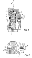
- the assembly 1 shown in Figure 1 comprises a so-called dual-mass flywheel 2, having a secondary mass 3 with a component 4 made of cast iron material.
- the cast component 4 is by means of a plurality of distributed over the circumference screw 5 connected to the housing 6 of a friction clutch 7.
- the secondary flywheel 3 is via a bearing 8 on a primary flywheel 9th rotatably mounted.
- the primary flywheel 9 is about screws 10 with a not closer shown output shaft of an internal combustion engine connectable.
- the made of cast iron component 4 with connected to a flange 11, the radially outside loading area for energy storage 12, which is part of a between the two masses 3 and 4 arranged Torsional vibration damper are.
- the components of the primary flywheel 9 limit one annular space 13 in which the energy storage formed by the helical compression springs 12 are included.
- the screwed with the cast component 4 friction clutch 7 has a pressure plate 14, which is rotatably connected to the housing 6, but limited axially displaceable connected. Axial between the pressure plate 14 and a friction surface of the cast component 4 are the friction linings of a Clutch disc 15 clamped. In known manner, a so-called Pad suspension between the friction linings of the clutch disc 15 may be provided.
- a Anpresstellerfeder 16 pivotally mounted, which is the pressure plate 14 charged.
- a screw 5 is first inserted into a recess 17 of the coupling housing 6 and then into a Verschraubungsaus principleung 18 of the cast component 4 screwed.
- the VerschraubungsausNOung 18 in which the screw 5 is screwed, smooth, so formed without thread profiling.
- Such a Verschraubungsaus supraung 18 can be made for example by simple drilling.
- the screw 5 has a thread 19 which is formed such that when screwing the screw 5 in the screwing 18 in the wall of this recess 18 a flow of material or a material displacement takes place, whereby a thread is formed.
- the Screw 5 thus allows a chip-free production of a thread within the recess 18th
- the thread 19 of the screw 5 at least over a partial length 21 with a screwing the screw 5 and the forming of the screw thread is provided with improving coating. It can be useful, for example be when the thread or even the whole screw is phosphated. Additionally or Alternatively, at least over a partial length 21, a lubricant or lubricant 22nd be upset. For this example, a lubricating varnish or a grease can be used. It is particularly advantageous if the partial length 21 of the screw thread 19 with paraffin is coated. Such a coating can in a particularly simple manner by means of a Dipping process are applied. Paraffin also has sufficient toughness or Strength, so that it is guaranteed that even during transport already coated supplied with the paraffin coating.
- screw connections according to the invention can usually in cast components required tapping omitted.
- the end region 23 of the threaded shank 24 has a frusto-conical configuration, which ensures that when inserting the Screw 5 in the recesses 17 and 18 already an axial orientation and lateral Guide the screw 5 is present, creating a perfect screwing the screw. 5 is possible.
- the cone angle 25 of the frusto-conical region 23 are on the order of between 12 ° and 20 °, preferably of the order of magnitude between 14 ° and 17 °.
Landscapes
- Engineering & Computer Science (AREA)
- General Engineering & Computer Science (AREA)
- Mechanical Engineering (AREA)
- Mechanical Operated Clutches (AREA)
Applications Claiming Priority (2)
| Application Number | Priority Date | Filing Date | Title |
|---|---|---|---|
| DE102004007338 | 2004-02-14 | ||
| DE102004007338 | 2004-02-14 |
Publications (2)
| Publication Number | Publication Date |
|---|---|
| EP1564422A1 true EP1564422A1 (fr) | 2005-08-17 |
| EP1564422B1 EP1564422B1 (fr) | 2007-02-07 |
Family
ID=34684061
Family Applications (1)
| Application Number | Title | Priority Date | Filing Date |
|---|---|---|---|
| EP05002010A Expired - Lifetime EP1564422B1 (fr) | 2004-02-14 | 2005-02-01 | Procédé et vis pour relier deux unités de construction d'un embrayage de frottement |
Country Status (3)
| Country | Link |
|---|---|
| EP (1) | EP1564422B1 (fr) |
| AT (1) | ATE353407T1 (fr) |
| DE (2) | DE502005000358D1 (fr) |
Cited By (2)
| Publication number | Priority date | Publication date | Assignee | Title |
|---|---|---|---|---|
| CN102248507A (zh) * | 2011-06-09 | 2011-11-23 | 俞钟晓 | 引导螺丝准入螺纹孔的装置 |
| WO2015106856A1 (fr) * | 2014-01-17 | 2015-07-23 | Bayerische Motoren Werke Aktiengesellschaft | Dispositif de fixation établissant un contact électrique |
Families Citing this family (2)
| Publication number | Priority date | Publication date | Assignee | Title |
|---|---|---|---|---|
| DE102008041391A1 (de) * | 2008-08-20 | 2010-01-14 | Kamax-Werke Rudolf Kellermann Gmbh & Co. Kg | Hochfeste Schraube mit Bainitgefüge |
| DE102011055497A1 (de) | 2011-11-18 | 2013-05-23 | Kamax Holding Gmbh & Co. Kg | Ultrahochfeste Schraube mit hohem Streckgrenzverhältnis |
Citations (6)
| Publication number | Priority date | Publication date | Assignee | Title |
|---|---|---|---|---|
| US3537288A (en) * | 1965-10-22 | 1970-11-03 | P D Robertson Mfg Co Ltd | Method of manufacturing self-tapping screws |
| GB1357720A (en) * | 1973-04-11 | 1974-06-26 | Altenloh Brinck & Co | Self-tapping screw |
| US3918345A (en) * | 1961-06-27 | 1975-11-11 | Res Eng & Mfg | Thread forming fasteners |
| EP0004541A1 (fr) * | 1978-02-17 | 1979-10-17 | B E L I P A R, Société Anonyme | Vis, notamment vis autotaraudeuse et machine à laminer les filets pour sa fabrication |
| US4529826A (en) * | 1983-07-28 | 1985-07-16 | Enichimica Secondaria S.P.A. | Solid lubricant and process for preparing it |
| DE19524827A1 (de) * | 1994-07-20 | 1996-01-25 | Luk Lamellen & Kupplungsbau | Reibungskupplung |
-
2005
- 2005-02-01 AT AT05002010T patent/ATE353407T1/de not_active IP Right Cessation
- 2005-02-01 EP EP05002010A patent/EP1564422B1/fr not_active Expired - Lifetime
- 2005-02-01 DE DE502005000358T patent/DE502005000358D1/de not_active Expired - Lifetime
- 2005-02-02 DE DE200510004712 patent/DE102005004712A1/de not_active Withdrawn
Patent Citations (6)
| Publication number | Priority date | Publication date | Assignee | Title |
|---|---|---|---|---|
| US3918345A (en) * | 1961-06-27 | 1975-11-11 | Res Eng & Mfg | Thread forming fasteners |
| US3537288A (en) * | 1965-10-22 | 1970-11-03 | P D Robertson Mfg Co Ltd | Method of manufacturing self-tapping screws |
| GB1357720A (en) * | 1973-04-11 | 1974-06-26 | Altenloh Brinck & Co | Self-tapping screw |
| EP0004541A1 (fr) * | 1978-02-17 | 1979-10-17 | B E L I P A R, Société Anonyme | Vis, notamment vis autotaraudeuse et machine à laminer les filets pour sa fabrication |
| US4529826A (en) * | 1983-07-28 | 1985-07-16 | Enichimica Secondaria S.P.A. | Solid lubricant and process for preparing it |
| DE19524827A1 (de) * | 1994-07-20 | 1996-01-25 | Luk Lamellen & Kupplungsbau | Reibungskupplung |
Cited By (3)
| Publication number | Priority date | Publication date | Assignee | Title |
|---|---|---|---|---|
| CN102248507A (zh) * | 2011-06-09 | 2011-11-23 | 俞钟晓 | 引导螺丝准入螺纹孔的装置 |
| WO2015106856A1 (fr) * | 2014-01-17 | 2015-07-23 | Bayerische Motoren Werke Aktiengesellschaft | Dispositif de fixation établissant un contact électrique |
| US9799967B2 (en) | 2014-01-17 | 2017-10-24 | Bayerische Motoren Werke Aktiengesellschaft | Electrically Contacting Fastening Device |
Also Published As
| Publication number | Publication date |
|---|---|
| ATE353407T1 (de) | 2007-02-15 |
| DE102005004712A1 (de) | 2005-08-25 |
| DE502005000358D1 (de) | 2007-03-22 |
| EP1564422B1 (fr) | 2007-02-07 |
Similar Documents
| Publication | Publication Date | Title |
|---|---|---|
| DE102012212174A1 (de) | Kupplungsaggregat | |
| DE10327437A1 (de) | Hydraulisches System | |
| DE102012218729A1 (de) | Drehschwingungsdämpfungsanordnung für den Antriebsstrang eines Fahrzeugs | |
| EP2805080A1 (fr) | Embrayage à friction à bain d'huile, à système amortisseur intégré | |
| WO2018158033A1 (fr) | Dispositif de transmission pour une boîte de vitesse d'un véhicule ou similaire | |
| DE102013223758A1 (de) | Wandlereinheit mit einem Dämpfungssystem und mit einer Drehmomentübertragungseinheit | |
| EP1489263B1 (fr) | Liaison arbre-moyeu d'un turbocompresseur | |
| DE112012001532T5 (de) | Differentialbaugruppe | |
| EP1564422B1 (fr) | Procédé et vis pour relier deux unités de construction d'un embrayage de frottement | |
| DE102014211633A1 (de) | Lamellenträger für eine Doppelkupplung | |
| DE102012210006A1 (de) | Kupplungsaggregat und Verfahren zur Montage eines Kupplungsaggregats | |
| DE102006000109A1 (de) | Kolben für ein Automatikgetriebe | |
| EP3963231B1 (fr) | Dispositif de frein à disques multiples ainsi qu'ensemble de transmission comprenant le dispositif de frein à disques multiples | |
| DE102012220441A1 (de) | Lamelle für eine Doppelkupplung mit Fliehkraftpendel | |
| DE102008033671A1 (de) | Adapterring zur Verbindung einer Getriebepumpenanordnung mit einem Motor | |
| WO2020143868A1 (fr) | Disque d'embrayage pourvu d'une unité d'amortissement pour un embrayage à friction | |
| EP2379909B1 (fr) | Amortisseur de vibrations de torsion comprenant un côté primaire et procédé pour produire une masse primaire d'un amortisseur de vibrations de torsion | |
| DE102014212169A1 (de) | Zweimassenschwungrad | |
| DE10200992B4 (de) | Torsionsschwingungsdämpfer | |
| DE102004016960A1 (de) | Schwungradanordnung | |
| DE102013226939A1 (de) | Drehschwingungsdämpfungsanordnung für den Antriebsstrang eines Fahrzeugs | |
| DE102014214970A1 (de) | Stützvorrichtung für eine Tellerfeder einer Reibkupplung mit einer Rotationsachse | |
| DE4331454B4 (de) | Verfahren zurHerstellung eines metallischen Körpers mit Ausnehmungen | |
| EP2100052B1 (fr) | Patin de glissement pour amortisseur de vibrations de torsion, tôle séparatrice pourvue d'un patin de glissement, amortisseur de vibrations de torsion pourvu d'un patin de glissement et procédé de production d'un patin de glissement | |
| DE102013208669A1 (de) | Ausgleichsmasse und Drehmomentübertragungseinrichtung |
Legal Events
| Date | Code | Title | Description |
|---|---|---|---|
| PUAI | Public reference made under article 153(3) epc to a published international application that has entered the european phase |
Free format text: ORIGINAL CODE: 0009012 |
|
| AK | Designated contracting states |
Kind code of ref document: A1 Designated state(s): AT BE BG CH CY CZ DE DK EE ES FI FR GB GR HU IE IS IT LI LT LU MC NL PL PT RO SE SI SK TR |
|
| AX | Request for extension of the european patent |
Extension state: AL BA HR LV MK YU |
|
| 17P | Request for examination filed |
Effective date: 20060217 |
|
| AKX | Designation fees paid |
Designated state(s): AT BE BG CH CY CZ DE DK EE ES FI FR GB GR HU IE IS IT LI LT LU MC NL PL PT RO SE SI SK TR |
|
| GRAP | Despatch of communication of intention to grant a patent |
Free format text: ORIGINAL CODE: EPIDOSNIGR1 |
|
| GRAS | Grant fee paid |
Free format text: ORIGINAL CODE: EPIDOSNIGR3 |
|
| GRAA | (expected) grant |
Free format text: ORIGINAL CODE: 0009210 |
|
| AK | Designated contracting states |
Kind code of ref document: B1 Designated state(s): AT BE BG CH CY CZ DE DK EE ES FI FR GB GR HU IE IS IT LI LT LU MC NL PL PT RO SE SI SK TR |
|
| PG25 | Lapsed in a contracting state [announced via postgrant information from national office to epo] |
Ref country code: PL Free format text: LAPSE BECAUSE OF FAILURE TO SUBMIT A TRANSLATION OF THE DESCRIPTION OR TO PAY THE FEE WITHIN THE PRESCRIBED TIME-LIMIT Effective date: 20070207 Ref country code: FI Free format text: LAPSE BECAUSE OF FAILURE TO SUBMIT A TRANSLATION OF THE DESCRIPTION OR TO PAY THE FEE WITHIN THE PRESCRIBED TIME-LIMIT Effective date: 20070207 Ref country code: SI Free format text: LAPSE BECAUSE OF FAILURE TO SUBMIT A TRANSLATION OF THE DESCRIPTION OR TO PAY THE FEE WITHIN THE PRESCRIBED TIME-LIMIT Effective date: 20070207 Ref country code: IE Free format text: LAPSE BECAUSE OF FAILURE TO SUBMIT A TRANSLATION OF THE DESCRIPTION OR TO PAY THE FEE WITHIN THE PRESCRIBED TIME-LIMIT Effective date: 20070207 Ref country code: NL Free format text: LAPSE BECAUSE OF FAILURE TO SUBMIT A TRANSLATION OF THE DESCRIPTION OR TO PAY THE FEE WITHIN THE PRESCRIBED TIME-LIMIT Effective date: 20070207 Ref country code: DK Free format text: LAPSE BECAUSE OF FAILURE TO SUBMIT A TRANSLATION OF THE DESCRIPTION OR TO PAY THE FEE WITHIN THE PRESCRIBED TIME-LIMIT Effective date: 20070207 |
|
| REG | Reference to a national code |
Ref country code: GB Ref legal event code: FG4D Free format text: NOT ENGLISH |
|
| REG | Reference to a national code |
Ref country code: CH Ref legal event code: EP |
|
| REG | Reference to a national code |
Ref country code: IE Ref legal event code: FG4D Free format text: LANGUAGE OF EP DOCUMENT: GERMAN |
|
| REF | Corresponds to: |
Ref document number: 502005000358 Country of ref document: DE Date of ref document: 20070322 Kind code of ref document: P |
|
| PG25 | Lapsed in a contracting state [announced via postgrant information from national office to epo] |
Ref country code: SE Free format text: LAPSE BECAUSE OF FAILURE TO SUBMIT A TRANSLATION OF THE DESCRIPTION OR TO PAY THE FEE WITHIN THE PRESCRIBED TIME-LIMIT Effective date: 20070507 Ref country code: BG Free format text: LAPSE BECAUSE OF FAILURE TO SUBMIT A TRANSLATION OF THE DESCRIPTION OR TO PAY THE FEE WITHIN THE PRESCRIBED TIME-LIMIT Effective date: 20070507 |
|
| PG25 | Lapsed in a contracting state [announced via postgrant information from national office to epo] |
Ref country code: ES Free format text: LAPSE BECAUSE OF FAILURE TO SUBMIT A TRANSLATION OF THE DESCRIPTION OR TO PAY THE FEE WITHIN THE PRESCRIBED TIME-LIMIT Effective date: 20070518 |
|
| PG25 | Lapsed in a contracting state [announced via postgrant information from national office to epo] |
Ref country code: IS Free format text: LAPSE BECAUSE OF FAILURE TO SUBMIT A TRANSLATION OF THE DESCRIPTION OR TO PAY THE FEE WITHIN THE PRESCRIBED TIME-LIMIT Effective date: 20070607 |
|
| PG25 | Lapsed in a contracting state [announced via postgrant information from national office to epo] |
Ref country code: PT Free format text: LAPSE BECAUSE OF FAILURE TO SUBMIT A TRANSLATION OF THE DESCRIPTION OR TO PAY THE FEE WITHIN THE PRESCRIBED TIME-LIMIT Effective date: 20070709 |
|
| NLV1 | Nl: lapsed or annulled due to failure to fulfill the requirements of art. 29p and 29m of the patents act | ||
| ET | Fr: translation filed | ||
| GBV | Gb: ep patent (uk) treated as always having been void in accordance with gb section 77(7)/1977 [no translation filed] |
Effective date: 20070207 |
|
| REG | Reference to a national code |
Ref country code: IE Ref legal event code: FD4D |
|
| PG25 | Lapsed in a contracting state [announced via postgrant information from national office to epo] |
Ref country code: SK Free format text: LAPSE BECAUSE OF FAILURE TO SUBMIT A TRANSLATION OF THE DESCRIPTION OR TO PAY THE FEE WITHIN THE PRESCRIBED TIME-LIMIT Effective date: 20070207 Ref country code: GB Free format text: LAPSE BECAUSE OF FAILURE TO SUBMIT A TRANSLATION OF THE DESCRIPTION OR TO PAY THE FEE WITHIN THE PRESCRIBED TIME-LIMIT Effective date: 20070207 |
|
| PLBE | No opposition filed within time limit |
Free format text: ORIGINAL CODE: 0009261 |
|
| STAA | Information on the status of an ep patent application or granted ep patent |
Free format text: STATUS: NO OPPOSITION FILED WITHIN TIME LIMIT |
|
| PG25 | Lapsed in a contracting state [announced via postgrant information from national office to epo] |
Ref country code: RO Free format text: LAPSE BECAUSE OF FAILURE TO SUBMIT A TRANSLATION OF THE DESCRIPTION OR TO PAY THE FEE WITHIN THE PRESCRIBED TIME-LIMIT Effective date: 20070207 Ref country code: CZ Free format text: LAPSE BECAUSE OF FAILURE TO SUBMIT A TRANSLATION OF THE DESCRIPTION OR TO PAY THE FEE WITHIN THE PRESCRIBED TIME-LIMIT Effective date: 20070207 |
|
| 26N | No opposition filed |
Effective date: 20071108 |
|
| PG25 | Lapsed in a contracting state [announced via postgrant information from national office to epo] |
Ref country code: LT Free format text: LAPSE BECAUSE OF FAILURE TO SUBMIT A TRANSLATION OF THE DESCRIPTION OR TO PAY THE FEE WITHIN THE PRESCRIBED TIME-LIMIT Effective date: 20070207 |
|
| PG25 | Lapsed in a contracting state [announced via postgrant information from national office to epo] |
Ref country code: GR Free format text: LAPSE BECAUSE OF FAILURE TO SUBMIT A TRANSLATION OF THE DESCRIPTION OR TO PAY THE FEE WITHIN THE PRESCRIBED TIME-LIMIT Effective date: 20070508 |
|
| BERE | Be: lapsed |
Owner name: LUK LAMELLEN UND KUPPLUNGSBAU BETEILIGUNGS K.G. Effective date: 20080228 |
|
| PG25 | Lapsed in a contracting state [announced via postgrant information from national office to epo] |
Ref country code: MC Free format text: LAPSE BECAUSE OF NON-PAYMENT OF DUE FEES Effective date: 20080228 |
|
| PG25 | Lapsed in a contracting state [announced via postgrant information from national office to epo] |
Ref country code: EE Free format text: LAPSE BECAUSE OF FAILURE TO SUBMIT A TRANSLATION OF THE DESCRIPTION OR TO PAY THE FEE WITHIN THE PRESCRIBED TIME-LIMIT Effective date: 20070207 |
|
| PG25 | Lapsed in a contracting state [announced via postgrant information from national office to epo] |
Ref country code: BE Free format text: LAPSE BECAUSE OF NON-PAYMENT OF DUE FEES Effective date: 20080228 |
|
| PG25 | Lapsed in a contracting state [announced via postgrant information from national office to epo] |
Ref country code: AT Free format text: LAPSE BECAUSE OF NON-PAYMENT OF DUE FEES Effective date: 20080201 |
|
| PG25 | Lapsed in a contracting state [announced via postgrant information from national office to epo] |
Ref country code: CY Free format text: LAPSE BECAUSE OF FAILURE TO SUBMIT A TRANSLATION OF THE DESCRIPTION OR TO PAY THE FEE WITHIN THE PRESCRIBED TIME-LIMIT Effective date: 20070207 |
|
| REG | Reference to a national code |
Ref country code: CH Ref legal event code: PL |
|
| PG25 | Lapsed in a contracting state [announced via postgrant information from national office to epo] |
Ref country code: CH Free format text: LAPSE BECAUSE OF NON-PAYMENT OF DUE FEES Effective date: 20090228 Ref country code: LI Free format text: LAPSE BECAUSE OF NON-PAYMENT OF DUE FEES Effective date: 20090228 |
|
| PG25 | Lapsed in a contracting state [announced via postgrant information from national office to epo] |
Ref country code: LU Free format text: LAPSE BECAUSE OF NON-PAYMENT OF DUE FEES Effective date: 20080201 Ref country code: HU Free format text: LAPSE BECAUSE OF FAILURE TO SUBMIT A TRANSLATION OF THE DESCRIPTION OR TO PAY THE FEE WITHIN THE PRESCRIBED TIME-LIMIT Effective date: 20070808 |
|
| PG25 | Lapsed in a contracting state [announced via postgrant information from national office to epo] |
Ref country code: TR Free format text: LAPSE BECAUSE OF FAILURE TO SUBMIT A TRANSLATION OF THE DESCRIPTION OR TO PAY THE FEE WITHIN THE PRESCRIBED TIME-LIMIT Effective date: 20070207 |
|
| PGFP | Annual fee paid to national office [announced via postgrant information from national office to epo] |
Ref country code: IT Payment date: 20080228 Year of fee payment: 4 |
|
| REG | Reference to a national code |
Ref country code: DE Ref legal event code: R081 Ref document number: 502005000358 Country of ref document: DE Owner name: SCHAEFFLER TECHNOLOGIES AG & CO. KG, DE Free format text: FORMER OWNER: SCHAEFFLER TECHNOLOGIES GMBH & CO. KG, 91074 HERZOGENAURACH, DE Effective date: 20120828 Ref country code: DE Ref legal event code: R081 Ref document number: 502005000358 Country of ref document: DE Owner name: SCHAEFFLER TECHNOLOGIES GMBH & CO. KG, DE Free format text: FORMER OWNER: SCHAEFFLER TECHNOLOGIES GMBH & CO. KG, 91074 HERZOGENAURACH, DE Effective date: 20120828 |
|
| REG | Reference to a national code |
Ref country code: FR Ref legal event code: TP Owner name: SCHAEFFLER TECHNOLOGIES AG & CO. KG, DE Effective date: 20130408 |
|
| REG | Reference to a national code |
Ref country code: DE Ref legal event code: R081 Ref document number: 502005000358 Country of ref document: DE Owner name: SCHAEFFLER TECHNOLOGIES GMBH & CO. KG, DE Free format text: FORMER OWNER: SCHAEFFLER TECHNOLOGIES AG & CO. KG, 91074 HERZOGENAURACH, DE Effective date: 20140214 Ref country code: DE Ref legal event code: R081 Ref document number: 502005000358 Country of ref document: DE Owner name: SCHAEFFLER TECHNOLOGIES AG & CO. KG, DE Free format text: FORMER OWNER: SCHAEFFLER TECHNOLOGIES AG & CO. KG, 91074 HERZOGENAURACH, DE Effective date: 20140214 |
|
| REG | Reference to a national code |
Ref country code: FR Ref legal event code: PLFP Year of fee payment: 11 |
|
| REG | Reference to a national code |
Ref country code: DE Ref legal event code: R081 Ref document number: 502005000358 Country of ref document: DE Owner name: SCHAEFFLER TECHNOLOGIES AG & CO. KG, DE Free format text: FORMER OWNER: SCHAEFFLER TECHNOLOGIES GMBH & CO. KG, 91074 HERZOGENAURACH, DE Effective date: 20150213 |
|
| PGFP | Annual fee paid to national office [announced via postgrant information from national office to epo] |
Ref country code: FR Payment date: 20150227 Year of fee payment: 11 |
|
| REG | Reference to a national code |
Ref country code: FR Ref legal event code: ST Effective date: 20161028 |
|
| PG25 | Lapsed in a contracting state [announced via postgrant information from national office to epo] |
Ref country code: FR Free format text: LAPSE BECAUSE OF NON-PAYMENT OF DUE FEES Effective date: 20160229 |
|
| PGFP | Annual fee paid to national office [announced via postgrant information from national office to epo] |
Ref country code: DE Payment date: 20190426 Year of fee payment: 15 |
|
| REG | Reference to a national code |
Ref country code: DE Ref legal event code: R119 Ref document number: 502005000358 Country of ref document: DE |
|
| PG25 | Lapsed in a contracting state [announced via postgrant information from national office to epo] |
Ref country code: DE Free format text: LAPSE BECAUSE OF NON-PAYMENT OF DUE FEES Effective date: 20200901 |
|
| P01 | Opt-out of the competence of the unified patent court (upc) registered |
Effective date: 20230523 |