EP0004609A2 - Système cryogénique à compresseur et détendeur à vis - Google Patents
Système cryogénique à compresseur et détendeur à vis Download PDFInfo
- Publication number
- EP0004609A2 EP0004609A2 EP79100877A EP79100877A EP0004609A2 EP 0004609 A2 EP0004609 A2 EP 0004609A2 EP 79100877 A EP79100877 A EP 79100877A EP 79100877 A EP79100877 A EP 79100877A EP 0004609 A2 EP0004609 A2 EP 0004609A2
- Authority
- EP
- European Patent Office
- Prior art keywords
- compressor
- expander
- housing
- rotors
- refrigerator system
- Prior art date
- Legal status (The legal status is an assumption and is not a legal conclusion. Google has not performed a legal analysis and makes no representation as to the accuracy of the status listed.)
- Ceased
Links
Images


Classifications
-
- F—MECHANICAL ENGINEERING; LIGHTING; HEATING; WEAPONS; BLASTING
- F25—REFRIGERATION OR COOLING; COMBINED HEATING AND REFRIGERATION SYSTEMS; HEAT PUMP SYSTEMS; MANUFACTURE OR STORAGE OF ICE; LIQUEFACTION SOLIDIFICATION OF GASES
- F25B—REFRIGERATION MACHINES, PLANTS OR SYSTEMS; COMBINED HEATING AND REFRIGERATION SYSTEMS; HEAT PUMP SYSTEMS
- F25B9/00—Compression machines, plants or systems, in which the refrigerant is air or other gas of low boiling point
- F25B9/06—Compression machines, plants or systems, in which the refrigerant is air or other gas of low boiling point using expanders
-
- F—MECHANICAL ENGINEERING; LIGHTING; HEATING; WEAPONS; BLASTING
- F04—POSITIVE - DISPLACEMENT MACHINES FOR LIQUIDS; PUMPS FOR LIQUIDS OR ELASTIC FLUIDS
- F04C—ROTARY-PISTON, OR OSCILLATING-PISTON, POSITIVE-DISPLACEMENT MACHINES FOR LIQUIDS; ROTARY-PISTON, OR OSCILLATING-PISTON, POSITIVE-DISPLACEMENT PUMPS
- F04C27/00—Sealing arrangements in rotary-piston pumps specially adapted for elastic fluids
- F04C27/008—Sealing arrangements in rotary-piston pumps specially adapted for elastic fluids for other than working fluid, i.e. the sealing arrangements are not between working chambers of the machine
- F04C27/009—Shaft sealings specially adapted for pumps
-
- F—MECHANICAL ENGINEERING; LIGHTING; HEATING; WEAPONS; BLASTING
- F25—REFRIGERATION OR COOLING; COMBINED HEATING AND REFRIGERATION SYSTEMS; HEAT PUMP SYSTEMS; MANUFACTURE OR STORAGE OF ICE; LIQUEFACTION SOLIDIFICATION OF GASES
- F25B—REFRIGERATION MACHINES, PLANTS OR SYSTEMS; COMBINED HEATING AND REFRIGERATION SYSTEMS; HEAT PUMP SYSTEMS
- F25B1/00—Compression machines, plants or systems with non-reversible cycle
- F25B1/04—Compression machines, plants or systems with non-reversible cycle with compressor of rotary type
- F25B1/047—Compression machines, plants or systems with non-reversible cycle with compressor of rotary type of screw type
-
- F—MECHANICAL ENGINEERING; LIGHTING; HEATING; WEAPONS; BLASTING
- F25—REFRIGERATION OR COOLING; COMBINED HEATING AND REFRIGERATION SYSTEMS; HEAT PUMP SYSTEMS; MANUFACTURE OR STORAGE OF ICE; LIQUEFACTION SOLIDIFICATION OF GASES
- F25B—REFRIGERATION MACHINES, PLANTS OR SYSTEMS; COMBINED HEATING AND REFRIGERATION SYSTEMS; HEAT PUMP SYSTEMS
- F25B2309/00—Gas cycle refrigeration machines
- F25B2309/06—Compression machines, plants or systems characterised by the refrigerant being carbon dioxide
Definitions
- This invention is directed to a cryogenic system wherein both the compressor and expander, which operate with the cryogenic refrigerant fluid in the system, are rotary screw type machinery of the Lysholm type.
- Lysholm built an early prototype of the rotary screw compressor in 1934. Some of his development work was described in the Proceedings of the Institution of Mechanical Engineers, Vol. 150, No.1, Pages 11-16 and 4 plates 1943.
- One of the main features of this screw compressor is the fact that it can run without oil or other lubricant in the compression chamber. No oil is necessary because the rotors do not contact each other or the casing. The only mechanical contact is in the bearings and in the timing gears which can be located on the outside of the casing and away from the refrigerant gas flow stream.
- the Lysholm type rotary screw compressor has two rotors with intermeshing lobes. Within the intermesh of the lobes and housing, the compression takes place.
- Two helical rotors comprise the working . parts of the screw compressor.
- the male rotor generally has four lobes and rotates 50 percent faster than the female rotor which has six flutes between which are grooves in which the lobes interengage. Other ratios of lobes to flutes are also used.
- the gas is compressed in the spaces between the housing, the lobes and the grooves.
- the lobes and the grooves are helical so that the space appears to move progressively toward the outlet end of the housing, and the space becomes progressively smaller along the length of the rotors as the rotors rotate.
- Nilsson, U.S. Patent 3,245,612 and Schibbye, U.S.Patents 3,283,996 and 3,423,01? are particularly directed to the shapes of the lands and the grooves in the rotors, but show the porting and general organization of the rotary screw compressor to show how compression and expansion are achieved in such a structure.
- this type of screw compressor is illustrated as being the compressor in refrigerator systems in U.S.Patents 3,432,089; 3,811,291; 3,848,422 and 3,945,216. While the use of screw compressors has been recognized for refrigerator compressor service, the use of such devices as expanders has not been recognized.
- screw compressors and expanders in the same refrigerator can efficiently run at about the same speed so that they can be coupled directly or through gearing, for speed control of the expander and for power feedback from the expander.
- gearing for speed control of the expander and for power feedback from the expander.
- piston expanders have been used, usually in smaller refrigerators
- turbo expanders have been used, usually in larger refrigerators. While the work output of such expanders is not significant in terms of total refrigerator input power, speed control of the expander is necessary. Such speed control has been difficult where the turbo expander runs at very high speed.
- this invention is directed to a screw compressor-expander refrigeration system wherein a screw compressor compresses a refrigerant gas,which is cooled by heat exchange and delivered to a screw expander which expands the refrigerant gas for the cooling thereof, with the expander being coupled to the compressor to feed work to the compressor and regulate expander speed, so that refrigeration is achieved.
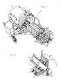
- a screw compressor-expander mechanism is generally indicated at 10.
- the mechanism 10 is used in conjunction with an external refrigerant circuit 12, see Fig.6, to result in the screw compressor-expander cryogenic system of this invention.
- the mechanism 10 broadly comprises a motor 14 which drives a compressor 16 and which is also coupled to an expander 18.
- the motor 14 comprises a motor housing 20 within which is mounted the electrical windings .and the rotor of the motor 14.
- Fig.6 shows a power supply 21 connected to the motor 14 for supplying the requisite electric power thereto.
- the supply 21 may include a.source, such as a solar array, and a power conditioning system when the refrigerator 10 is deployed in space.
- Power supply 21 may be a more conventional power line, generator or battery when the refrigerator 10 is used on ground, air, or shipboard equipment.
- a shaft 22 extends from the housing 20 on its right end.
- the shaft 22 is mounted on a pair of antifriction bearings 24 and 26, on the ends thereof, for the rotary support of the rotary portions of the motor.
- the ball bearings 24 and 26 are mounted in a pair of respective bosses 28 and 30, and the bosses are mounted on the motor housing.
- a cover 32 encloses the exterior of the bearing 24 and the boss 28.
- An oil inlet connection 34 furnishes oil to the bearing 24 while an oil outlet connection 36 returns the oil from the interior of the cover 32 for recirculation.
- a seal 38 prevents the entrance of oil from the region of the bearing 24 into the interior of the motor housing 20.
- a cover 40 protects the exterior of the motor housing and the bearing assembly of which the bearing 24 is a part.
- An oil tube 42 may be wrapped around the motor housing 20, or oil passages may be provided within the exterior structure of the motor housing 20 to provide for coolant flow to carry away the heat of the motor 14. Oil tube 42 is part of the general lubrication system of the mechanism 10, and it may be the tube which supplies the oil inlet connection 34.
- Cover 40 protects the exterior of the motor housing 20, the cooling oil tube 42, and the bearing structure under the cover 32.
- the shaft 22 extends out of the boss 30 and beyond the bearing 26 and has an interior spline 44.
- a housing 46 surrounds the boss 30 and has an interior boss 48 therein.
- the boss 48 has a shaft 50 therein in alignment with shaft 22 and a shaft 52 therein oriented in parallel to the shaft 50.
- the shafts 50 and 52 are respectively supported on a bearing 54 and.a bearing 56.
- a seal 58 is located around the shaft 50 interiorly and adjacent to the bearing 54 while a seal 60 is positioned around the shaft 52 and adjacent the bearing 56.
- a timing gear 62 is mounted on the shaft 50 while a timing gear 64 is mounted on the shaft 52.
- the timing gear 62 is the drive gear and it engages the timing gear 64 which is the driven gear.
- the shaft 50 has an exterior spine 66 adjacent the gear 62 and extending into and engaging the spine 44. By this construction, with rotation of the motor shaft 22, the shafts 50 and 52 also rotate. Oil is supplied within the housing 46 to lubricate the bearings 26, 54 and 56. The oil also lubricates the spline coupling defined by the splines 44 and 66, as well as lubricates the mesh of the gears 62 and 64.
- the housing 46 serves as the oil sump and interiorly thereof is located the oil pump 68 which takes suction through an appropriate suction line from the oil within the sump.
- the suction line 70 and the oil pump 68 are specifically designed to pump in accordance with the local ambient conditions.
- the suction may be a filter in the bottom of the sump (from a gravitational viewpoint) while in non- gravitational or very low gravitational requirement, the pump suction may be especially designed to pick up globules of oil floating free within the housing, and/or suction may pick up oil which is moving by surface tension on the inside of the walls of the housing 46.
- the housing 46 may be completely filled with oil so the pump 68 operates like in gravitational conditions.
- the oil pump 68 delivers oil to the various needs of the mechanism 10, including the lubrication of the bearing 24 and the cooling of the motor 20. There are other lubricant requirements in the mechanism 10, described hereinafter, and these are also supplied by the pump 68.
- a connection 74 and a connection 76 are through flow connections for the housing 46.
- the oil discharge from the pump 68 may be cooled as in a cooler 78 illustrated in Fig.1.
- the various connections illustrated on the cooler 78 illustrate connections for the utilization of oil from the cooler.
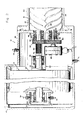
- a compressor housing 80 houses a lobed screw compressor rotor 82 on shaft 50 and a mating recessed rotor 84 on the shaft 52.
- the rotors 82 and 84 closely interfit with each other, and closely interfit with the casing 80 both radially and at the ends.
- the housing 80 has an opening on the side of the housing 80 adjacent the intermesh of the rotors at one end thereof to define an inlet zone 86 to which is connected a suction line 88, see Fig.6.
- At the other end of the housing 80, also at the intermesh between the rotors 82 and 84 is an outlet zone 90 to which is connected an outlet line 92.
- the right hand ends of the shafts 50 and 52 are rotatably supported in a set of anti-friction bearings 94 and 96 respectively which are in turn protected by seals 98 and 100 respectively.
- the inlet and outlet ports in association with the inlet and outlet zones 86 and 90 are disclosed in several of the patents discussed in the background.
- the shapes of the rotors 82 and 84, in connection with the inlet and outlet ports and the compressor housing 80 are such that compression is achieved in the space between the rotors and the end of the housing 80.
- individual spaces defined by the lobes and recesses of the rotors appear to proceed along in the housing. In the present case, rotation is such that the procession appears to be from left to right.
- the inlet port in the left end of the housing 80 is cut off, the volume of the space appears to decrease so that compression takes place. When compression reaches the desired value,then the outlet port is uncovered to discharge the compressed gas to the outlet line 92.
- a cooling chamber 102 may embrace the high pressure end of the compressor housing 80 to remove some of the heat of compression, if required to maintain reasonable temperature gradients and limits in the housing, rotors and appurtenant structure.
- the cooling chamber 102 may be supplied with circulating oil as a coolant, or may employ another coolant, as desired.
- a housing 104 is flanged to the right end of the compressor housing 80.
- the housing 104 contains a pair of expander shafts 106 and 108 which are mounted on a pair of bearings 110 and 112 and which are sealed by a pair of seals 114 and 116.
- a pair of timing gears 118 and 120 are respectively mounted on the shafts 106 and 108. The timing gears interengage to maintain the shafts at particular interrelated angular positions and angular rate ratios.
- the shaft 106 is coupled to the shaft 50 by means of spline coupling 122 so that the shaft 106 turns with the shaft 50, and the shaft 108 turns with the shaft 106.
- the expander can be placed close to the refrigeration load while the compressor 16 may be located conveniently to the source of power and/or a location where the heat of compression can be rejected.
- ambient refrigeration gas is piped to and from the compressor to the location of the expander 18.
- the cryogenic heat exchanger between inlet and outlet expander gas would be located close to the expander.
- speed control of the expander would be achieved by a separate motor/generator directly or gear coupled to the expander shaft 106.
- the expander canrun at a higher speed than the compressor. A higher speed is feasible because the expander 18 is smaller in physical size than the compressor 16.
- the shafts 106 and 108 are tubular and extend into an expander housing 124.
- a lobed rotor 126 is mounted on the shaft 106 while a rotor 128 having mating recesses thereon is mounted on the shaft 108.
- the lobes and recesses of the rotors 126 and 128 intermate and define spaces which act to expand gas. They are of the same nature as the compressor rotors in that the expansion takes place in the spaces between the housing 124 and the rotors 126 and 128.
- the criteria for the construction of this expander is the same as for the Lysholm type compressors discussed above, except that the structure runs in the opposite direction. As seen in Fig.6, an inlet line 130 is connected to the inlet port of the expander 18 while an outlet line 132 is connected to the outlet port of expander 18.
- the expander housing 124 is mounted on tubular supports, such as a tubular support 134 seen in Fig.3 which is mounted on the housing 104.
- the support 134 is in supporting engagement with the expander housing 124.
- a tubular support 136 extends between the expander housing 124 and a bearing housing. 138.
- a dewar housing 140 encloses the expander 18 and mounts on the housing 124.
- the dewar housing 140 insulates the expander 18 which operates at cryogenic temperatures.
- bearing housing 130 is mounted on the outer end of the dewar housing 140.
- the hollow shafts 106 and 108 extend through the rotors and are rotatably supported in the bearing housing 138 in a pair of bearings 142 and 144, see Figs. 3 and 5.
- the bearings 142 and 144 are respectively protected by a seal 146 and a seal 148.
- Lubricant is supplied and drained from the bearings 142 and 144 by means of an oil inlet 147 and an oil outlet 149.
- These provisions for oiling permit the circulation of oil from the oil pump 68 through the bearing area and out therefrom. Since the expander 18 is cold, the oil may supply heat to the bearings 142 and 144 to keep them temperature stabilized.
- the shafts 106 and 108 are hollowed tubes to limit heat transfer to the physical structure of the expander from the region of the bearings.
- thermal plugs are fitted into the shafts at the ends inside the bearings and the seals.
- a thermal plug 150 is illustrated as being within the shaft 106 interiorly of the bearing 110 and the seal 114, while a thermal plug 152 is illustrated as being in the interior of the tubular end of the shaft 106 interiorly of the bearing 142 and the seal 146.
- a sleeve 154 is fitted exteriorly of the shaft 106 within the seal 114 while a sleeve 156 is fitted exteriorly of the shaft 106 interiorly of seal.146.
- These sleeves are fitted throughout, within the seals, as for example the sleeve 158 fitted exteriorly of the shaft 50 within the seal 98.
- Fig. 4 illustrates the seal 98 in more detail.
- the shaft 50 has the sleeve 158 positioned on its exterior.
- the sleeve 158 is of magnetizable material and acts as a pole-piece, and is necessary when the shaft 50 is of non-magnetic material. In cases where the shaft 50 is of magnetizable material, the sleeve 158 is not required.
- a bushing 160 in the form of a tubular cylinder which is axially magnetized is provided around the sleeve 158.
- the bushing 160 is a permanent magnet but a solenoid coil could be substituted.
- a magnetic pole piece 162 is positioned at one end of the magnetic bushing 160 and a magnetic pole piece 164 is positioned at the other end of the magnet bushing 160.
- the pole pieces are in the form of rings and are sealed within a bore 166 in the housing 80 by means of an 0-ring 168 and an 0-ring 170 respectively.
- the pole pieces 162 and 164 have annular grooves therein such as a groove 172 in the pole piece 162 and a groove 174 in the pole piece 164. These grooves concentrate the magnetic field in the radial space between the pole pieces and the sleeve 158.
- the lubricant supplied to the bearing 94 is of oily-type material. It may be of hydrocarbon base or silicone base, so that it supplies the lubricant at an acceptable viscosity over the operating range of the mechanism 10. Furthermore, very finely divided magnetizable iron particles are present in the lubricant supply.
- iron particles are sufficiently small to pass through any filters in the lubrication system and are small enough that they do not reduce the life of the anti-friction bearings.
- the lubricant can circulate through the bearings, as through the bearing 94 and reach the annular space between the pole piece 164 and the sleeve 158.
- a magnetizable particle diameter in the rangeof 50 to 100 Angstroms is satisfactory in this work.
- a hard packing 178 is provided between the sleeve 158 and the end of the bore 166 to minimize heat transfer from the compressed gas to the seal area.
- a plurality of axially oriented cooling holes are drilled into the shaft 50 from the end underneath the bearing, all the way underneath the seal.
- a hole 180 is shown in Fig.4, and is exemplary of several such holes drilled parallel to the axis, and positioned off axis just under sleeve 158. These cooling holes permit the circulation of oil into the region beneath the seal 98 to carry heat away from the seal area to maintain seal temperatures.
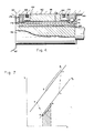
- the system operates in an environment in which the mechanism 10 is generally at about 300° K, when in equilibrium with the ambient.
- the compressor suction line 88 is at 199° K and 1/2 atmosphere absolute. See point 1 in Fig. 7.
- the refrigerant gas is nitrogen in the present operating cycle example, but.may be nitrogen, argon, helium or neon depending on the desired refrigeration temperature.
- the screw compressor 16 is driven by the motor 14 with the lobed rotor 82 running about 10,000 REM. In this example the rotor 82 has 4 lobes while the rotor 84 has 5 recesses.
- the screw compressor 16 is such as to raise the pressure in the outlet line 92 to 1 atmosphere at point 2 in Fig.?.
- a heat exchanger 184 rejects heat to the ambient, as by fluid circulating in the circulating line 186.
- the circulating line 186 may carry a liquid or a gas, or in space applications may directly radiate heat to space.
- heat is rejected from the refrigerant gas so that in the line 188 the conditions are as at point 3 in Fig.?. Temperature is at 300°K.
- a heat exchanger 190 is a counterflow heat exchanger with heat exchange between the fluid in line 188 and the refrigerant fluid flowing to the compressor in suction line 88.
- the refrigerant gas is cooled from point 3 to point 4 in the TS diagram of Fig. 7.
- the fluid flows from the heat exchanger into expander inlet line 130. At that point, the refrigerant gas is at 185° K.
- the expander 18 in the present example is running at the same speed as the compressor, because the lobed rotor 126 thereof is running at the same speed as the lobed rotor 82 of the compressor 16. It is understood that if desired, a gear box may be employed within the housing 104 so that the expander may run at a different speed. However, the present preferred embodiment is to have the two shafts run at the same speed, in view of the mechanical simplicity. There is not believed to be a sufficient thermodynamic advantage to operate at a different speed to warrant the additional complexity caused by the gear connection. In either a direct drive situation as illustrated in Fig.3, or in a gear drive, the expander rotors are coupled to the compressor rotors which in turn are controlled inspeed by the drive motor 14.
- the refrigerant gas is expanded to the suction pressure of one half atmosphere and to 177°K, at point 5. This is the condition in the outlet line 132.
- the refrigerant may be a mixed vapor-liquid fluid at the expander outlet.
- the screw expander 10 can handle such a mixed fluid without damage.
- a refrigeration load 192 supplies heat to the refrigerant gas. It is here that the useful refrigeration is achieved.
- a refrigerator heat load 193 is illustrated in Fig.6 as delivering heat at below ambient temperatures to the refrigeration load heat exchanger 192.
- the refrigeration load 193 is equipment which requires a subambient temperature for proper operation.
- the refrigeration temperature is about 180 0 K, with 177 0 K gas going into the refrigeration load and 184 0 X gas coming out of the refrigeration load in a line 194.
- the conditions in line 194 are represented at point 6 in Fig.7 and represent the cold input to the heat eschanger 190. Fluid in the line 194 passes through the heat exchange 190 to the line 88 and exchanges heat therein. This closes the cycle.
- the above are calculated values.
- the dewar housing 140 is insulated in order to maintain the expander 18 in a cool condition, with a minimum amount of heat conducted and radiated into the expander.
- the refrigeration heat load 192 is schematically shown exteriorly to the dewar 140 in Fig.6, but may be interiorly thereof, as an infrared radiation detector, or other refrigeration load.
- the mass flow rate of the system depends upon the gas, the amount of cooling desired and the refrigeration temperature.
- the compressor rotor 82 and the expander rotor 126 are sized to handle the mass flow rate.
- the working pressure increase in the compressor is one half atmosphere. In a medium size machine, the compressor rotor 82 runs at 10,000 RPM.
- the present system Compared to Stirling cycle machines and Vuilleumeir machines, the present system has a favorable specific power consumption and has a better chance to reach maintenance-free life of up to ten years, and accordingly is particularly useful.
Landscapes
- Engineering & Computer Science (AREA)
- Mechanical Engineering (AREA)
- General Engineering & Computer Science (AREA)
- Physics & Mathematics (AREA)
- Thermal Sciences (AREA)
- Applications Or Details Of Rotary Compressors (AREA)
- Rotary-Type Compressors (AREA)
Applications Claiming Priority (2)
| Application Number | Priority Date | Filing Date | Title |
|---|---|---|---|
| US89467778A | 1978-04-10 | 1978-04-10 | |
| US894677 | 1978-04-10 |
Publications (2)
| Publication Number | Publication Date |
|---|---|
| EP0004609A2 true EP0004609A2 (fr) | 1979-10-17 |
| EP0004609A3 EP0004609A3 (fr) | 1979-10-31 |
Family
ID=25403389
Family Applications (1)
| Application Number | Title | Priority Date | Filing Date |
|---|---|---|---|
| EP79100877A Ceased EP0004609A3 (fr) | 1978-04-10 | 1979-03-23 | Système cryogénique à compresseur et détendeur à vis |
Country Status (3)
| Country | Link |
|---|---|
| EP (1) | EP0004609A3 (fr) |
| JP (2) | JPS54154813A (fr) |
| IL (1) | IL56763A (fr) |
Cited By (6)
| Publication number | Priority date | Publication date | Assignee | Title |
|---|---|---|---|---|
| GB2124306A (en) * | 1982-06-22 | 1984-02-15 | Pauline Elsie Rowe | Heat engine |
| EP0030636B1 (fr) * | 1979-12-10 | 1984-03-21 | Hughes Aircraft Company | Système cryogénique à compresseur et détendeur à vis, muni d'un accouplement magnétique |
| EP0676600A3 (fr) * | 1994-04-05 | 1996-12-18 | Carrier Corp | Turbine avec écoulement à deux phases. |
| WO2020201843A1 (fr) | 2019-04-05 | 2020-10-08 | Atlas Copco Airpower, Naamloze Vennootschap | Système de production d'énergie et procédé de production d'énergie par exploitation d'un tel système de production d'énergie |
| BE1027172A1 (nl) | 2019-04-05 | 2020-10-27 | Atlas Copco Airpower Nv | Systeem voor vermogensopwekking en werkwijze voor het opwekken van vermogen door gebruik van dergelijk systeem voor vermogensopwekking |
| CN114060271A (zh) * | 2021-12-06 | 2022-02-18 | 珠海格力电器股份有限公司 | 螺杆式压缩机及制冷设备 |
Families Citing this family (7)
| Publication number | Priority date | Publication date | Assignee | Title |
|---|---|---|---|---|
| JPS6051621B2 (ja) * | 1980-04-16 | 1985-11-14 | 株式会社前川製作所 | 冷凍又はヒ−トポンプのサイクルの動力回収方法 |
| JPS6051622B2 (ja) * | 1980-04-26 | 1985-11-14 | 株式会社前川製作所 | ヒートポンプサイクルと熱併給蒸気サイクルの組合せからなる給熱設備におけるエネルギー有効利用方法 |
| JPH027412Y2 (fr) * | 1987-07-28 | 1990-02-22 | ||
| BE1020312A3 (nl) | 2012-02-28 | 2013-07-02 | Atlas Copco Airpower Nv | Compressorinrichting, evenals gebruik van zulke opstelling. |
| US11015602B2 (en) | 2012-02-28 | 2021-05-25 | Atlas Copco Airpower, Naamloze Vennootschap | Screw compressor |
| BE1020311A3 (nl) | 2012-02-28 | 2013-07-02 | Atlas Copco Airpower Nv | Schroefcompressor. |
| CN103277309A (zh) * | 2013-06-17 | 2013-09-04 | 上海大隆机器厂有限公司 | 一种双螺杆压缩机的同步齿轮装置 |
Family Cites Families (11)
| Publication number | Priority date | Publication date | Assignee | Title |
|---|---|---|---|---|
| US1440000A (en) * | 1920-05-03 | 1922-12-26 | Charles E Bonine | Refrigeration |
| US1673153A (en) * | 1922-06-15 | 1928-06-12 | Maclaren Electric Appliance Co | Refrigerating machine |
| DE609405C (de) * | 1933-01-04 | 1935-02-14 | Aeg | Luftkaeltemaschine |
| FR796274A (fr) * | 1934-10-16 | 1936-04-03 | Milo Ab | Compresseur ou moteur hélicoïdal |
| DE699427C (de) * | 1938-10-01 | 1940-11-28 | Julius Pintsch Kom Ges | Offene Kaltluftmaschine |
| US2804260A (en) * | 1949-07-11 | 1957-08-27 | Svenska Rotor Maskiner Ab | Engines of screw rotor type |
| GB882213A (en) * | 1958-06-04 | 1961-11-15 | Netzschkau Maschf Nema | Gas refrigeration machine |
| US3184155A (en) * | 1963-04-17 | 1965-05-18 | Cooper Bessemer Corp | Motor compressor unit |
| DE2034213C3 (de) * | 1969-10-10 | 1985-04-25 | Ferrofluidics Corp., Burlington, Mass. | Magnetdichtung zur Abdichtung von Dichtungsspalten |
| AU4325272A (en) * | 1971-06-21 | 1973-12-13 | Vilter Manufacturing Corp | Rotary screw type, internal combustion engine |
| DE2636024A1 (de) * | 1976-08-11 | 1978-03-23 | Hans Meyer | Rotationskolbenmaschine mit kaemmverschluss als entspannungs-/verdichtungsmaschine mit kontinuierlich fortlaufender prozessfuehrung, sowie damit ausfuehrbare arbeitsprozesse zur energie-gewinnung, einsparung, -rueckgewinnung und -erzeugung |
-
1979
- 1979-02-28 IL IL56763A patent/IL56763A/xx unknown
- 1979-03-23 EP EP79100877A patent/EP0004609A3/fr not_active Ceased
- 1979-04-06 JP JP4191679A patent/JPS54154813A/ja active Pending
-
1985
- 1985-03-04 JP JP1985030739U patent/JPS60162868U/ja active Granted
Cited By (6)
| Publication number | Priority date | Publication date | Assignee | Title |
|---|---|---|---|---|
| EP0030636B1 (fr) * | 1979-12-10 | 1984-03-21 | Hughes Aircraft Company | Système cryogénique à compresseur et détendeur à vis, muni d'un accouplement magnétique |
| GB2124306A (en) * | 1982-06-22 | 1984-02-15 | Pauline Elsie Rowe | Heat engine |
| EP0676600A3 (fr) * | 1994-04-05 | 1996-12-18 | Carrier Corp | Turbine avec écoulement à deux phases. |
| WO2020201843A1 (fr) | 2019-04-05 | 2020-10-08 | Atlas Copco Airpower, Naamloze Vennootschap | Système de production d'énergie et procédé de production d'énergie par exploitation d'un tel système de production d'énergie |
| BE1027172A1 (nl) | 2019-04-05 | 2020-10-27 | Atlas Copco Airpower Nv | Systeem voor vermogensopwekking en werkwijze voor het opwekken van vermogen door gebruik van dergelijk systeem voor vermogensopwekking |
| CN114060271A (zh) * | 2021-12-06 | 2022-02-18 | 珠海格力电器股份有限公司 | 螺杆式压缩机及制冷设备 |
Also Published As
| Publication number | Publication date |
|---|---|
| IL56763A0 (en) | 1979-05-31 |
| IL56763A (en) | 1981-12-31 |
| JPS6347824Y2 (fr) | 1988-12-09 |
| EP0004609A3 (fr) | 1979-10-31 |
| JPS54154813A (en) | 1979-12-06 |
| JPS60162868U (ja) | 1985-10-29 |
Similar Documents
| Publication | Publication Date | Title |
|---|---|---|
| US4291547A (en) | Screw compressor-expander cryogenic system | |
| US4328684A (en) | Screw compressor-expander cryogenic system with magnetic coupling | |
| EP0004609A2 (fr) | Système cryogénique à compresseur et détendeur à vis | |
| US11486396B2 (en) | Variable capacity screw compressor and method | |
| US3913346A (en) | Liquid refrigerant injection system for hermetic electric motor driven helical screw compressor | |
| US8024942B2 (en) | Method and apparatus for highly efficient compact vapor compression cooling | |
| US5222874A (en) | Lubricant cooled electric drive motor for a compressor | |
| US6109040A (en) | Stirling cycle refrigerator or engine employing the rotary wankel mechanism | |
| EP2218983A2 (fr) | Appareil frigorifique à compresseur à vis | |
| US20150030490A1 (en) | Bearing Housing and Assembly of a Screw Compressor | |
| JPH07504252A (ja) | スクロール式流体装置用の断熱配列 | |
| US20160268874A1 (en) | Liquefaction system and power generation system | |
| US4311021A (en) | Screw compressor-expander cryogenic system with mist lubrication | |
| US3537269A (en) | Rotary stirling cycle refrigerating system | |
| EP3755884B1 (fr) | Appareil thermodynamique de roticulation | |
| US10309398B1 (en) | Passage arrangement for cooling, lubricating and reducing the size of rotary machines | |
| CS207321B2 (en) | Compressor set | |
| US11022348B2 (en) | Caloric heat pump for an appliance | |
| US3236062A (en) | Refrigerant compressor with lubricant cooling | |
| CA1036375A (fr) | Appareil de refroidissement et de chauffage a fluide unique et moteur thermique | |
| JPS6160997B2 (fr) | ||
| JPH01167490A (ja) | 空気圧縮機の潤滑油冷却方法 | |
| JPH0424621B2 (fr) | ||
| Carter | A Study of the Injection Refrigeration Cycle as Applied to a Novel Type Compressor | |
| JPS642796B2 (fr) |
Legal Events
| Date | Code | Title | Description |
|---|---|---|---|
| PUAI | Public reference made under article 153(3) epc to a published international application that has entered the european phase |
Free format text: ORIGINAL CODE: 0009012 |
|
| PUAL | Search report despatched |
Free format text: ORIGINAL CODE: 0009013 |
|
| AK | Designated contracting states |
Designated state(s): CH DE FR GB IT NL SE |
|
| AK | Designated contracting states |
Designated state(s): CH DE FR GB IT NL SE |
|
| 17P | Request for examination filed | ||
| STAA | Information on the status of an ep patent application or granted ep patent |
Free format text: STATUS: THE APPLICATION HAS BEEN REFUSED |
|
| 18R | Application refused |
Effective date: 19820429 |
|
| RIN1 | Information on inventor provided before grant (corrected) |
Inventor name: LEO, BRUNO S. |