EP0004809A2 - Vorrichtung zum Reinigen von endlosen Förderbandgurten - Google Patents
Vorrichtung zum Reinigen von endlosen Förderbandgurten Download PDFInfo
- Publication number
- EP0004809A2 EP0004809A2 EP79400197A EP79400197A EP0004809A2 EP 0004809 A2 EP0004809 A2 EP 0004809A2 EP 79400197 A EP79400197 A EP 79400197A EP 79400197 A EP79400197 A EP 79400197A EP 0004809 A2 EP0004809 A2 EP 0004809A2
- Authority
- EP
- European Patent Office
- Prior art keywords
- support member
- sleeve
- integral
- cage
- rod
- Prior art date
- Legal status (The legal status is an assumption and is not a legal conclusion. Google has not performed a legal analysis and makes no representation as to the accuracy of the status listed.)
- Ceased
Links
Images


Classifications
-
- B—PERFORMING OPERATIONS; TRANSPORTING
- B65—CONVEYING; PACKING; STORING; HANDLING THIN OR FILAMENTARY MATERIAL
- B65G—TRANSPORT OR STORAGE DEVICES, e.g. CONVEYORS FOR LOADING OR TIPPING, SHOP CONVEYOR SYSTEMS OR PNEUMATIC TUBE CONVEYORS
- B65G45/00—Lubricating, cleaning, or clearing devices
- B65G45/10—Cleaning devices
- B65G45/12—Cleaning devices comprising scrapers
Definitions
- the present invention relates to a cleaning device for an endless belt conveyor, comprising a set of independent scrapers placed under the return strand of the belt or tangentially to a drum of the conveyor.
- each squeegee is mounted at one end of a metal blade whose other end is secured to a support.
- This device has a number of drawbacks.
- frequent adjustments of the squeegee position must be provided as a result of permanent deformation of the metal blades.
- the latter are, moreover, subject to rupture, which requires their replacement at relatively short time intervals.
- the main object of the invention is to avoid the aforementioned drawbacks.
- each squeegee is kept constantly in contact with the face of the strip to be cleaned with a small pressure variation during wear of the squeegee, which removes practically any adjustment during the duration of life of said squeegee.
- the invention essentially consists in replacing the usual metal blades with fiberglass rods, so that the device meets the required requirements and that, in particular, its adjustment means are practically used only in the event of replacement of the squeegees. worn, therefore in very rare conditions.
- a more specific subject of the invention is a belt cleaning device for an endless belt conveyor, comprising a set of independent scrapers connected to a support member by means of elastic elements, characterized in that each elastic element is consisting of a fiberglass rod, and in that means are provided for adjusting the position of the support member of said rods.
- Each end of a rod is glued inside a socket, one of these sockets being secured to the squeegee, and the other to the support member.
- Each rod is cylindrical or conical in shape.
- each squeegee on a socket is ensured by at least one rivet.
- the sleeve integral with the support member is externally threaded and is provided, on either side of said support member, with two braked nuts ensuring its fixing and its height adjustment.
- the socket integral with the support member is obtained from a screw held in position by nuts, an elastic shock-absorbing element being interposed between the socket and the support member.
- the sleeve integral with the support member is slidably mounted inside a cylindrical sleeve, the height adjustment of the support member being secured by means of a screw rotating inside a nut welded to said sleeve.
- the support member is mounted, at each of its ends, on a cage sliding vertically inside a fixed frame, said cage being associated with angular adjustment means of the support member.
- the angular adjustment means comprise a lever secured to the support member, for driving said support member in rotation, a rod linked to the lever ensuring its locking in position on the cage.
- the angular adjustment means comprise a first plate on which the end of the support member is welded, and a second plate integral with the cage is disposed against said first plate, said second plate being provided with two buttonhole-shaped openings making it possible to secure the two plates by means of bolts, after the first plate has been brought into position by rotation of the support member.
- the angular adjustment means comprise a spiral spring wound around the end of the support member, one end of said spring being fixed to said support member, and the other end, of shape straight, constituting a lever cooperating with notches on the outside of the cage.
- each squeegee or group of squeegees is adjusted to different heights so as to adapt the device to the profile of the strip to be cleaned.
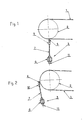
- FIGS. 1 and 2 we see a belt 1 of an endless belt conveyor, the reference 2 of which designates the head drum.
- a cleaning device, marked 3 as a whole, is held against the strip 1 either under the lower strand thereof (case of FIG. 1), or tangentially to the drum 2 (case of FIG. 2).
- the device 3 which includes one or more independent squeegees such as the squeegee 4 or the squeegee 5.
- Each squeegee - is connected to a support member 6 via fiberglass rods such as 7 6u 8.
- the ring 7 is cylindrical in shape drique, while the rod 8 is conical.
- the support member 6 consists of a piece of tubular shape with a square section, horizontally elongated.
- the support member 6 could of course be shaped differently (round tube or L-shaped cross member).
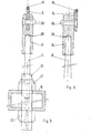
- the ends of a rod 7 or 8 are glued to the inside of sockets such as sockets 9 and 11 of FIG. 5.
- a variant 10 of the socket 9 is illustrated in FIG.
- FIG. 6 while two variants 12 and 13 of the sleeve 11 are shown in Figures 11 and 12.
- the sleeves are provided with a vent such that 29 allowing air to escape during the bonding operation.
- These sockets are made integral with the squeegees 4 or 5 using rivets such as 30.
- the squeegees 4 and 5 have holes, respectively 14 and 15.
- These squeegees are, moreover, provided with a rod wear 16 made of very hard material, tungsten carbide for example fixed by brazing or gluing on said squeegees.
- the sleeve 11 is externally threaded and is held on the support member 6 by two braked nuts 17 which make it possible to adjust the height, according to the arrangement illustrated in FIG. 5.
- the sleeve 12, obtained from a screw is held on the support member 6 by the nuts 19 and 20 resting on the washer 18.
- An elastic shock absorbing element 21 is interposed between the support member 6 and the bush 12 which allows axial movement of the rod 7 or 8. This latter arrangement is illustrated in FIG. 11.
- the sleeve 13 slides in a cylindrical sleeve 22.
- the height adjustment is carried out by means of a screw 23 rotating inside d 'a nut 24 welded to the sleeve 22, the assembly being locked in the position chosen by the lock nut 25.
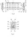
- each squeegee is associated with two rods 7.
- the overall arrangement corresponds to that illustrated in Figure 2, each squeegee 4 being fixed by riveting in a socket 10.
- each squeegee 4 being fixed by riveting in a socket 10.
- a reversible conveyor preferably using squeegees 5 fixed inside a bush 9, as shown in FIG. 5.
- FIG 4 there is shown an adjustment system for a device produced according to Figures 2, 3 and 5.
- the support member 6 is mounted at each of its ends on a frame marked 31 as a whole.
- Each chassis has a frame 32 inside which a cage 33 is slidably mounted in the vertical direction.
- the latter is crossed by a tubular piece 34 serving as a housing at the end of the support member 6.
- the height adjustment the latter is effected by means of a threaded rod 35 cooperating with nuts 36 and 37 respectively secured to the frame 32 and the cage 33.
- the angular adjustment is ensured by means of a lever 38, one end of which is fixed to the support member 6 and which can be positioned in notches 39 formed circularly in a notch of the tubular part 34 suitably cut at its upper part.
- the lever 38 is locked in position by a horizontal rod 40 integral with said lever.
- the end of the rod 40 opposite the point of attachment of the lever enters one of the orifices 41 of the cage 33 where it is blocked by a nut 4 2 .
- FIGs 13 and 14 illustrate an alternative embodiment of the adjustment system that has just been described.
- the support member 6 is welded at each of its ends to a plate 43 disposed against a plate 44 secured to the cage 33.
- the plate 44 is provided with two buttonholes 45 in an arc.
- the angular adjustment is carried out by rotation of the support member 6 which causes the rotation of the plate 43 of which it is integral.
- the blocking of the two plates is easily effected by means of bolts 46 passing through the plate 43 and the buttonhole 45 of the plate 44 previously brought into the desired position. Height adjustment is made kills in a manner identical to that described in the case of FIG. 4.
- FIGs 15 and 16 illustrate another alternative embodiment of the adjustment system.
- the angular adjustment is provided with torsional elasticity.
- the support member 6 is mounted on the chassis in a manner similar to that shown in Figure 4.
- a spiral spring 47 which is wound around the end of the support member 6.
- One end 48 of this spring is fixed to said support member while the opposite end 49 of rectilinear shape constitutes a lever capable of cooperating with notches 50 arranged in an arc of a circle on the face of the cage 33.
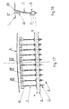
- Figures 17 and 18 illustrate one of the many possibilities for adjusting the device, in particular in the case of an assembly according to Figure 1.
- the wing scrapers 26 are inclined in order to adapt to the curvature that can keep the edges of the strip 1 after trimming the upper strand of the strip.
- the central squeegee (s) 27 are wedged higher than the intermediate squeegees 28, and this at the place where the strip 1 is most fouled.
- the invention therefore covers, in addition to the examples shown, their different possible variants.
Landscapes
- Engineering & Computer Science (AREA)
- Mechanical Engineering (AREA)
- Structure Of Belt Conveyors (AREA)
- Paper (AREA)
- Cleaning In General (AREA)
- Processing And Handling Of Plastics And Other Materials For Molding In General (AREA)
Applications Claiming Priority (2)
| Application Number | Priority Date | Filing Date | Title |
|---|---|---|---|
| FR7810415A FR2421825A1 (fr) | 1978-04-07 | 1978-04-07 | Dispositif de nettoyage de bande pour transporteur a bande sans fin |
| FR7810415 | 1978-04-07 |
Publications (2)
| Publication Number | Publication Date |
|---|---|
| EP0004809A2 true EP0004809A2 (de) | 1979-10-17 |
| EP0004809A3 EP0004809A3 (de) | 1979-10-31 |
Family
ID=9206861
Family Applications (1)
| Application Number | Title | Priority Date | Filing Date |
|---|---|---|---|
| EP79400197A Ceased EP0004809A3 (de) | 1978-04-07 | 1979-03-28 | Vorrichtung zum Reinigen von endlosen Förderbandgurten |
Country Status (4)
| Country | Link |
|---|---|
| EP (1) | EP0004809A3 (de) |
| JP (1) | JPS54136086A (de) |
| ES (1) | ES479071A1 (de) |
| FR (1) | FR2421825A1 (de) |
Cited By (19)
| Publication number | Priority date | Publication date | Assignee | Title |
|---|---|---|---|---|
| GB2125357A (en) * | 1982-08-06 | 1984-03-07 | Neville Reuben Thomas Stockton | Conveyor belt scraper mounting |
| EP0251051A3 (en) * | 1986-06-23 | 1988-08-10 | Hosch Fordertechnik Gmbh | Retention device at a conveyor belt scraper for a supporting beam provided with scraper elements |
| US4768644A (en) * | 1986-07-22 | 1988-09-06 | Vulkan Verfahrenstechnik B. Hackforth Gmbh & Co. Kg | Scraper device for conveyer belt systems |
| US4779716A (en) * | 1986-08-22 | 1988-10-25 | Gordon Balt Scrapers, Inc. | Conveyor belt cleaner |
| US4850474A (en) * | 1986-08-01 | 1989-07-25 | Schwarze Hans O | Stripping device for the return run of conveyor belts |
| GB2227991A (en) * | 1989-02-13 | 1990-08-15 | Conveyor Improvements | Conveyor belt scraper mechanism |
| EP0396890A1 (de) * | 1989-05-12 | 1990-11-14 | F.E. Schulte Strathaus KG | Vorrichtung zum Reinigen von Förderbändern |
| US5007523A (en) * | 1988-08-16 | 1991-04-16 | Morefield Allen J | Conveyor belt scraper mechanisms |
| DE8915279U1 (de) * | 1989-12-30 | 1991-04-25 | VSR Engineering GmbH Fördertechnik, 4330 Mülheim | Vertikalspannvorrichtung für Förderbandabstreifer u.dgl. |
| EP0481221A1 (de) * | 1990-10-10 | 1992-04-22 | HOSCH-FÖRDERTECHNIK GmbH | Leistenabstreifer |
| FR2685682A1 (fr) * | 1991-12-27 | 1993-07-02 | Scrap | Dispositif de raclage de la surface porteuse d'une bande de convoyage. |
| US5248026A (en) * | 1992-07-22 | 1993-09-28 | Morefield Allen J | Conveyor belt scraper mechanisms |
| DE19510362A1 (de) * | 1994-04-07 | 1995-10-12 | Vulka Ind Vulkanisation Gmbh | Abstreifer für Fördergurte |
| WO1995035252A1 (de) * | 1994-06-20 | 1995-12-28 | Widia Gmbh | Fördergutabstreifer |
| DE19508090A1 (de) * | 1995-03-08 | 1996-09-12 | Hans Dipl Ing Jostes | Abstreifvorrichtung zum Reinigen von Förderbändern mit einer Tragachse und mehreren darauf angeordneten Abstreiferelementen |
| WO1997000220A1 (en) * | 1995-06-16 | 1997-01-03 | Svedala Trellex Ab | Conveyor belt cleaning device and fastening device therefor |
| US5692595A (en) * | 1994-10-11 | 1997-12-02 | Mato Australia Pty. Ltd. | Scraper blade for belt conveyors |
| AU696111B2 (en) * | 1994-10-11 | 1998-09-03 | Mato Australia Pty Limited | Scraper blade for belt conveyors |
| DE10301230B4 (de) * | 2003-01-15 | 2006-06-14 | Jostes, Hans, Dipl.-Ing. | Abstreifvorrichtung zum Reinigen von Förderbändern |
Families Citing this family (1)
| Publication number | Priority date | Publication date | Assignee | Title |
|---|---|---|---|---|
| US4598823A (en) * | 1984-02-13 | 1986-07-08 | Martin Engineering Company | Conveyor belt cleaner |
Family Cites Families (9)
| Publication number | Priority date | Publication date | Assignee | Title |
|---|---|---|---|---|
| DD58900A (de) * | ||||
| DE58900C (de) * | A. BÖHM in Boskowitz, Mähren | Schlittschuh-Laufeisen mit Mittelrippe auf der Lauffläche | ||
| FR1303647A (fr) * | 1961-08-04 | 1962-09-14 | Cie Internationale Pour La Pro | Râcleur pour bandes transporteuses |
| US3504786A (en) * | 1968-01-02 | 1970-04-07 | Matson C G | Conveyor cleaner |
| US3504756A (en) * | 1968-09-11 | 1970-04-07 | Albert G Bodine | Method for providing efficient sonic coupling to the earth in a seismic survey system |
| IL34073A (en) * | 1969-03-19 | 1972-09-28 | Ward C | Conveyor belt cleaning apparatus |
| US3841470A (en) * | 1972-04-20 | 1974-10-15 | Nihon Tsusho Kk | Cleaner for conveyor belt |
| DE2319736C3 (de) * | 1973-04-18 | 1975-09-18 | Manfred 5810 Witten Schattauer | Abstreifvorrichtung für Gurtbänder |
| DE2402601C2 (de) * | 1974-01-19 | 1986-01-23 | Rotec Industries, Inc., Elmhurst, Ill. | Abstreichvorrichtung für ein Betonförderband |
-
1978
- 1978-04-07 FR FR7810415A patent/FR2421825A1/fr active Granted
-
1979
- 1979-03-28 EP EP79400197A patent/EP0004809A3/de not_active Ceased
- 1979-03-29 ES ES479071A patent/ES479071A1/es not_active Expired
- 1979-04-03 JP JP3937279A patent/JPS54136086A/ja active Pending
Cited By (21)
| Publication number | Priority date | Publication date | Assignee | Title |
|---|---|---|---|---|
| GB2125357A (en) * | 1982-08-06 | 1984-03-07 | Neville Reuben Thomas Stockton | Conveyor belt scraper mounting |
| US5082106A (en) * | 1986-01-08 | 1992-01-21 | Schwarze Hans O | Stripping device for the return run of conveyor belts |
| EP0251051A3 (en) * | 1986-06-23 | 1988-08-10 | Hosch Fordertechnik Gmbh | Retention device at a conveyor belt scraper for a supporting beam provided with scraper elements |
| US4768644A (en) * | 1986-07-22 | 1988-09-06 | Vulkan Verfahrenstechnik B. Hackforth Gmbh & Co. Kg | Scraper device for conveyer belt systems |
| US4850474A (en) * | 1986-08-01 | 1989-07-25 | Schwarze Hans O | Stripping device for the return run of conveyor belts |
| US4779716A (en) * | 1986-08-22 | 1988-10-25 | Gordon Balt Scrapers, Inc. | Conveyor belt cleaner |
| US5007523A (en) * | 1988-08-16 | 1991-04-16 | Morefield Allen J | Conveyor belt scraper mechanisms |
| GB2227991B (en) * | 1989-02-13 | 1992-05-20 | Conveyor Improvements | Conveyor belt scraper mechanism |
| GB2227991A (en) * | 1989-02-13 | 1990-08-15 | Conveyor Improvements | Conveyor belt scraper mechanism |
| EP0396890A1 (de) * | 1989-05-12 | 1990-11-14 | F.E. Schulte Strathaus KG | Vorrichtung zum Reinigen von Förderbändern |
| DE8915279U1 (de) * | 1989-12-30 | 1991-04-25 | VSR Engineering GmbH Fördertechnik, 4330 Mülheim | Vertikalspannvorrichtung für Förderbandabstreifer u.dgl. |
| EP0481221A1 (de) * | 1990-10-10 | 1992-04-22 | HOSCH-FÖRDERTECHNIK GmbH | Leistenabstreifer |
| FR2685682A1 (fr) * | 1991-12-27 | 1993-07-02 | Scrap | Dispositif de raclage de la surface porteuse d'une bande de convoyage. |
| US5248026A (en) * | 1992-07-22 | 1993-09-28 | Morefield Allen J | Conveyor belt scraper mechanisms |
| DE19510362A1 (de) * | 1994-04-07 | 1995-10-12 | Vulka Ind Vulkanisation Gmbh | Abstreifer für Fördergurte |
| WO1995035252A1 (de) * | 1994-06-20 | 1995-12-28 | Widia Gmbh | Fördergutabstreifer |
| US5692595A (en) * | 1994-10-11 | 1997-12-02 | Mato Australia Pty. Ltd. | Scraper blade for belt conveyors |
| AU696111B2 (en) * | 1994-10-11 | 1998-09-03 | Mato Australia Pty Limited | Scraper blade for belt conveyors |
| DE19508090A1 (de) * | 1995-03-08 | 1996-09-12 | Hans Dipl Ing Jostes | Abstreifvorrichtung zum Reinigen von Förderbändern mit einer Tragachse und mehreren darauf angeordneten Abstreiferelementen |
| WO1997000220A1 (en) * | 1995-06-16 | 1997-01-03 | Svedala Trellex Ab | Conveyor belt cleaning device and fastening device therefor |
| DE10301230B4 (de) * | 2003-01-15 | 2006-06-14 | Jostes, Hans, Dipl.-Ing. | Abstreifvorrichtung zum Reinigen von Förderbändern |
Also Published As
| Publication number | Publication date |
|---|---|
| ES479071A1 (es) | 1979-11-16 |
| FR2421825B1 (de) | 1981-10-23 |
| EP0004809A3 (de) | 1979-10-31 |
| JPS54136086A (en) | 1979-10-22 |
| FR2421825A1 (fr) | 1979-11-02 |
Similar Documents
| Publication | Publication Date | Title |
|---|---|---|
| FR2692516A1 (fr) | Dispositif de coupe pour une scie à moteur à chaîne. | |
| FR2657830A1 (fr) | Pied d'appui pour un dispositif d'appui telescopique pour remorque a sellette. | |
| EP1916182A1 (de) | Fahrrad-Steuerkopflager | |
| FR2885589A1 (fr) | Dispositif de fixation d'une selle sur une tete de tige de selle | |
| FR1464371A (fr) | Rotor pour appareils destinés à la désagrégation de la paille ou matière similaire | |
| EP1847322B1 (de) | Vorrichtung zum Montieren/Demontieren von mindestens einem Schneidmesser auf/von einem Rotor einer landwirtschaftlichen Maschine und mit einer solchen Vorrichtung ausgestattetes Werkzeug | |
| FR2517644A1 (fr) | Dispositif pour transporter des objets sur des galets de transport | |
| EP0328171B1 (de) | Halterung von Schabeblättern zum Reinigen von Förderbändern | |
| EP0481883A1 (de) | Verbesserung an der Gelenkeinrichtung eines langen Vielscharpfluges | |
| FR2658097A1 (fr) | Perfectionnement aux grilles de cribles pour carrieres ou autres. | |
| FR2470528A1 (fr) | Couteau de faucheuse | |
| BE1003796A3 (fr) | Dispositif de scarifiage. | |
| EP0165887B1 (de) | Bodenwalze und Landmaschine mit einer solchen Walze | |
| EP0564768B1 (de) | Anordnung zur elastischen Rückstellung eines Halteorgans in einem alpinen Bindungselement | |
| EP0135459A1 (de) | Scheibenmäher | |
| EP1004239B1 (de) | Torsionsfester Angelrutenhalter | |
| EP1382775A1 (de) | Rotorblatt und Rotor einer mechanischen Kelle, wie ein Betonpoliergerät | |
| FR2596996A1 (fr) | Structure pour le montage pivotant d'un cercle de basket-ball | |
| FR2924143A1 (fr) | Etai muni d'un renfort | |
| FR2845859A1 (fr) | Dispositif de securite pour outil aratoire et machine de traitement des sols equipee de tels dispositifs de securite | |
| FR2529743A1 (fr) | Dispositif de coupe pour machine de recolte | |
| EP0545831B1 (de) | Verstellbare Wippe, insbesondere für Spielzeug | |
| EP0592262A1 (de) | Schildvorrichtung zur Reinigung von Strassen und dergleichen | |
| FR2718326A1 (fr) | Dispositif d'effacement de barre de coupe. | |
| BE1002539A6 (fr) | Ebouseuse de prairie. |
Legal Events
| Date | Code | Title | Description |
|---|---|---|---|
| PUAI | Public reference made under article 153(3) epc to a published international application that has entered the european phase |
Free format text: ORIGINAL CODE: 0009012 |
|
| PUAL | Search report despatched |
Free format text: ORIGINAL CODE: 0009013 |
|
| AK | Designated contracting states |
Designated state(s): BE DE GB IT NL |
|
| AK | Designated contracting states |
Designated state(s): BE DE GB IT NL |
|
| 17P | Request for examination filed | ||
| STAA | Information on the status of an ep patent application or granted ep patent |
Free format text: STATUS: THE APPLICATION HAS BEEN REFUSED |
|
| 18R | Application refused |
Effective date: 19820315 |
|
| RIN1 | Information on inventor provided before grant (corrected) |
Inventor name: FINET, DANIEL |