EP0005108A2 - Installation et procédé d'alimentation de balises à lampes incandescentes - Google Patents
Installation et procédé d'alimentation de balises à lampes incandescentes Download PDFInfo
- Publication number
- EP0005108A2 EP0005108A2 EP79400240A EP79400240A EP0005108A2 EP 0005108 A2 EP0005108 A2 EP 0005108A2 EP 79400240 A EP79400240 A EP 79400240A EP 79400240 A EP79400240 A EP 79400240A EP 0005108 A2 EP0005108 A2 EP 0005108A2
- Authority
- EP
- European Patent Office
- Prior art keywords
- circuit
- switching
- installation according
- current
- wire
- Prior art date
- Legal status (The legal status is an assumption and is not a legal conclusion. Google has not performed a legal analysis and makes no representation as to the accuracy of the status listed.)
- Withdrawn
Links
Images

Classifications
-
- G—PHYSICS
- G05—CONTROLLING; REGULATING
- G05F—SYSTEMS FOR REGULATING ELECTRIC OR MAGNETIC VARIABLES
- G05F1/00—Automatic systems in which deviations of an electric quantity from one or more predetermined values are detected at the output of the system and fed back to a device within the system to restore the detected quantity to its predetermined value or values, i.e. retroactive systems
- G05F1/10—Regulating voltage or current
- G05F1/12—Regulating voltage or current wherein the variable actually regulated by the final control device is AC
- G05F1/40—Regulating voltage or current wherein the variable actually regulated by the final control device is AC using discharge tubes or semiconductor devices as final control devices
- G05F1/44—Regulating voltage or current wherein the variable actually regulated by the final control device is AC using discharge tubes or semiconductor devices as final control devices semiconductor devices only
-
- H—ELECTRICITY
- H02—GENERATION; CONVERSION OR DISTRIBUTION OF ELECTRIC POWER
- H02J—ELECTRIC POWER NETWORKS; CIRCUIT ARRANGEMENTS OR SYSTEMS FOR SUPPLYING OR DISTRIBUTING ELECTRIC POWER; SYSTEMS FOR STORING ELECTRIC ENERGY
- H02J11/00—Circuit arrangements for providing service supply to auxiliaries of stations in which electric power is generated, distributed or converted
-
- H—ELECTRICITY
- H02—GENERATION; CONVERSION OR DISTRIBUTION OF ELECTRIC POWER
- H02M—APPARATUS FOR CONVERSION BETWEEN AC AND AC, BETWEEN AC AND DC, OR BETWEEN DC AND DC, AND FOR USE WITH MAINS OR SIMILAR POWER SUPPLY SYSTEMS; CONVERSION OF DC OR AC INPUT POWER INTO SURGE OUTPUT POWER; CONTROL OR REGULATION THEREOF
- H02M5/00—Conversion of AC power input into AC power output, e.g. for change of voltage, for change of frequency, for change of number of phases
- H02M5/02—Conversion of AC power input into AC power output, e.g. for change of voltage, for change of frequency, for change of number of phases without intermediate conversion into DC
- H02M5/04—Conversion of AC power input into AC power output, e.g. for change of voltage, for change of frequency, for change of number of phases without intermediate conversion into DC by static converters
- H02M5/06—Conversion of AC power input into AC power output, e.g. for change of voltage, for change of frequency, for change of number of phases without intermediate conversion into DC by static converters using impedances
- H02M5/08—Conversion of AC power input into AC power output, e.g. for change of voltage, for change of frequency, for change of number of phases without intermediate conversion into DC by static converters using impedances using capacitors only
Definitions
- the present invention relates to an installation for supplying incandescent lamp beacons from an energy source coming from an insulated section of the shield wire of a power transmission line.
- incandescent lamp beacons to indicate the position of the pillars which support the conductor bundles of a power transmission line has been known for a long time.
- These beacons which are attached to the pillars, are intended not only to indicate to aircraft pilots the presence of a pillar, but also serve as reference points for maintenance and repair teams. So far, these beacons have been supplied by secondary distribution lines or by generators in the most distant places. Either of these forms of supply is however very expensive due to installation and maintenance costs and also unreliable.
- the present invention provides an installation which allows the supply of incandescent beacons directly from the guard wire of the power transmission line.
- the guard wire is this conductor, which is attached to the tip of the pillars and which serves to protect the bundles of conductors of the transmission line against lightning.
- This wire is normally connected to earth and is not used for the transport of electrical energy proper. However, due to its proximity to high-voltage conductor bundles, a certain amount of energy is induced therein capacitively.
- the present invention recommends a supply installation with regulation of the power supplied to the incandescent beacons, by means of an electronic assembly of minimal maintenance, of high reliability and relatively inexpensive.
- the present invention resides in an installation for supplying incandescent lamp beacons by the energy induced by capacitive coupling in a insulated section of a guard wire of an energy transmission line comprising a device for transforming the energy induced in the guard wire into alternating current and a switching circuit mounted in bypass on said transformer device for controlling the flow of said alternating current supplying at least one incandescent lamp.
- the present invention also relates to a supply method implemented by the installation described above.
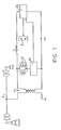
- Figure 1 schematically preserves the power supply installation by guard wire of incandescent beacons.
- the primary of the step-down transformer T has its primary connected between the insulated section of the protective wire F and the ground and generates a secondary current which supplies the incandescent lamps C, which are connected in series to a current detector R.
- La power delivered through incandescent lamps C is regulated by a shunt switching circuit I which is controlled by the control circuit IC.
- This control circuit consists of a comparator part and an integrator part.
- a smoothing inductor L is connected in series with switch 1 in order to compensate for sudden changes in current in this switch.
- the current supplied by the secondary of the transformer T flows freely in the circuit of incandescent lamps C when the switch I is in the open position.
- this switch When this switch is closed by the control circuit IC, it forms a short circuit through the secondary of the transformer, which has the effect of deriving all the energy from the ground.
- comparator reaches a predetermined threshold voltage.
- the capacitor C 3 connected in parallel with the diac D 2 acts as a filter for the transients and determines with the resistor R 4 the time of. conduction of the diac D 2 .
- Resistor R 4 in series with diac D 2 delimits the input current.
- D 2 When D 2 becomes conductive, it short-circuits the positive and negative terminals of the bridge BR 3 and the voltage at E appears at the terminal F of the bridge. A pulse then initiates the trigger of the triac TI which becomes conductive, thus short-circuiting the incandescent lamps C and the current detector, to derive to ground the energy extracted from the guard wire by the step-down transformer T.
- the inductance Smoothing L connected between triac TI and earth, prevents sudden changes in current and protects the secondary of the step-down transformer as well as the thyristor itself against peak voltages.
- Resistor R 5 is used to limit the current supply to the triac TI trigger while the MOV element in parallel with the triac acts as an overvoltage protection element and behaves like a double polarity Zener diode.
- the resistor R 6 connected between one of the electrodes of the triac and its trigger ensures a zero current there before the conduction of this triac.
- the transformer T secondary voltage goes to zero, the triac TI returns to its non-conduction state.
- the triac TI remains non-conductive and the incandescent lamps C are again supplied for a duration determined by the charging time of the capacitor C 2 . Once the capacitor C 2 is charged to a predetermined voltage by the comparator circuit, the triac TI again enters into conduction to limit the current supplied to the incandescent lamps C.
- the triac TI when started, is used to regulate the energy through the incandescent lamps C by short-circuiting the secondary of the step-down transformer T, which has the effect of delimit the power delivered to incandescent lamps C,
- the current detector R which is then open circuit, acts at the level of the control circuit IC, so as to advance the switching time of the circuit I, and this every half alternations of the source current. Advancing the switching time of circuit I has the effect of deriving from ground, all the energy coming from the guard wire source F.
- FIG. 2 illustrates in detail the installation for supplying incandescent beacons with regulation by shunt switching shown in FIG. 1.
- This regulation is carried out as follows.
- the current supplied by the secondary of the transformer T passes through the diode bridge BR 1 and the resistor R 2 to supply the trigger of the thyristor TR which becomes conductive
- the thyristor TR being conductive, the bridges diodes BR 1 and BR 2 as well as the capacitor C 1 , all connected in parallel with this thyristor, are short-circuited so that the supply of incandescent lamps C is done through the loop formed by the bridge BR 1 , the diode D 1 , the thyristor TR and the negative terminal of the bridge BR 1 .
- the power delivered to incandescent lamps C is regulated by means of a switching circuit connected to the terminals BC, through the secondary windings of the transformer thus short-circuiting incandescent lamps C of the caurart detection circuit formed BR 1 and BR 2 bridges and associated elements.
- the switching circuit consists of a bidirectional thyristor TI or triac, a MOV and resistors R 5 and R 6 .
- the firing of the triac TI is controlled by a control circuit which includes an integrator formed by the variable resistor R 7 and the capacitor C 2 and by a comparator consisting of the diode bridge BR 3 , the diac D 2 , the resistor R 4 and of capacitor C 3 .
- the capacitor C 2 of the integrator circuit charges at a voltage determined by the diac D 2 which becomes conductive when the voltage at the terminal ⁇ of the inoperative, that is to say when they constitute an open circuit, no current then flows through the diode bridges BP 1 and BR 2 of the current detector, so that the thyristor TR remains blocked.
- the integrator circuit is formed by capacitors CI and C 2 in series and the variable resistor R 7 , the value of which is adjusted according to the length of the section of the insulated ground wire.
- the insertion of the capacitor C 1 has the effect of reducing the time constant of the firing circuit of the thyristor TI, which is advanced over time.
- the value of the capacitor C 1 is chosen so as to engage the triac TI at the start of each half-wave so as to derive from ground almost all of the energy coming from the guard wire.
Landscapes
- Engineering & Computer Science (AREA)
- Power Engineering (AREA)
- Physics & Mathematics (AREA)
- Electromagnetism (AREA)
- General Physics & Mathematics (AREA)
- Radar, Positioning & Navigation (AREA)
- Automation & Control Theory (AREA)
- Circuit Arrangement For Electric Light Sources In General (AREA)
Abstract
Description
- La présente invention concerne une installation d'alimentation de balises à lampes incandescentes à partir d'une source d'énergie provenant d'une section isolée du fil de garde d'une ligne de transport d'énergie.
- L'usage de balises à lampes incandescentes pour indiquer la position des pilônes qui supportent les faisceaux de conducteur d'une ligne de transport d'énergie est connu depuis longtemps. Ces balises, qui sont fixées aux pilônes, ont pour but non seulement d'indiquer aux pilotes d'avion la présence d'un pilône, mais également servent de points de repères pour les équipes d'entretien et de dépannage. Jusqu'ici, ces balises ont été alimentées par des lignes de distribution secondaire ou par des groupes électrogènes dans les endroits les plus éloignés. L'une ou l'autre de ces formes d'alimentation s'avère toutefois très dispendieuse en raison des coûts d'installation et d'entretien et également peu fiable.
- Pour contrer ces désavantages afférents aux installations d'alimentation conventionnelles, la présente invention propose une installation qui permet l'alimentation des balises incandescentes directement du fil de garde de la ligne de transport d'énergie.
- Le fil de garde est ce conducteur accroché à la pointe des pilônes et qui sert à protéger les faisceaux de conducteurs de la ligne de transport contre la foudre. Ce fil est normalement relié à la terre et n'est pas utilisé au transport de l'énergie électrique proprement dit. Toutefois, en raison de sa proximité des faisceaux de conducteur à haute tension, une certaine quantité d'énergie y est induite de façon capacitive. En isolant une section de longueur prédéterminée du fil de garde, il est possible de récupérer l'énergie qui est induite, sans pour autant aliéner la fonction de protection du fil de garde. Pour ce faire, la présente invention préconise une installation d'alimentation avec régulation de la puissance fournie aux balises incandescentes, au moyen d'un ensemble électronique d'entretien minime, de grande fiabilité et relativement peu coûteux.
- De façon plus spécifique, la présente invention réside en une installation d'alimentation de balises à lampes incandescentes par l'énergie induite par couplage capacitif dans une section isolée d'un fil de garde d'une ligne de transport d'énergie comportant un dispositif de transformation de l'énergie induite dars le fil de garde en courant alternatif et un circuit de commutation monté en dérivation sur ledit dispositif de transformation pour contrôler le débit dudit courant alternatif alimentant au moins une lampe incandescente.
- La présente invention est également relative à une méthode d'alimentation mise en oeuvre par l'installation décrite ci-haut.
- Un mode de réalisation préféré de la présente invention sera décrit ci-après avec référence aux dessins annexés, dans lesquels :
- - la figure 1 illustre un schéma bloc de l'installation d'alimentation avec régulation par commutation shunt de balises à lampes incandescentes ;
- - la figure 2 montre le schéma détaillé de l'installation d'alimentation de la fag. 1.
- La figure 1 préserve de façon schématique l'installation d'alimentation par fil de garde de balises incandescentes. Le primaire du transformateur abaisseur de tension T a son primaire raccordé entre la section isolée du fil de garde F et la masse et génère au secondaire un courent qui alimente les lampes incandescentes C, lesquelles sont reliées en série à un détecteur de courant R. La puissance débitée à travers les lampes incandescentes C est régularisée par un circuit de commutation shunt I qui est commandé par le circuit de contrôle IC. Ce circuit de contrôle est constitué d'une partie comparateur et d'une partie intégrateur. En outre, une inductance de lissage L est reliée en série avec le commutateur 1 afin de pallier aux brusques variations de courant dans ce commutateur.
- En fonctionnement normal, le courant fourni par le secondaire du transformateur T passe librement dans le circuit des lampes incandescentes C lorsque le commutateur I est en position ouverte. Lorsque ce commutateur est fermé par le circuit de contrôle IC, il forme un court-circuit au travers le secondaire du transformateur, ce qui a pour effet de dériver à la masse toute l'énergie comparateur atteint une tension de seuil prédéterminée. Le condensateur C3 branché en parallèle avec le diac D2 joue le rôle de filtre pour les transitoires et détermine avec la résistance R4 le temps de . conduction du diac D2. La résistance R4 en série avec le diac D2 délimite le courant d'entrée. Lorsque D2 devient conducteur, il court- circuite les bornes positives et négatives du pont BR3 et la tension en E apparaît à la borne F du pont. Une impulsion amorce alors la gâchette du triac TI qui devient conducteur, court-circuitant ainsi les lampes incandescentes C et le détecteur de courant, pour dériver à la masse l'énergie extraite du fil de garde par le transformateur-abaisseur T. L'inductance de lissage L, branchée entre le triac TI et la masse, empêche les changements brusques du courant et protège le secondaire du transformateur-abaisseur ainsi que le thyristor lui- méme contre les tensions crêtes. La résistance R5 sert à limiter l'alimentation en courant de la gâchette du triac TI alors que l'élément MOV en parallèle avec le triac joue le rôle d'élément de protection de surtension et se comporte comme une diode Zener à double polarité. La résistance R6 connectée entre une des électrodes du triac et sa gâchette y assure un courant nul avant la mise en conduction de ce triac. Au moment du passage à zéro de la tension au secondaire du transformateur T, le triac TI retourne à son état de non-conduction.
- Au début de la demi-alternarce r.égative suivante, le triac TI demeure non-conducteur et les lampes incandescentes C sont à nouveau alimentées pour une durée déterminée par le temps de charge du condensateur C2. Une fois le condensateur C2 chargé à une tension prédéterminée par le circuit comparateur, le triac TI entre à nouveau en conduction pour limiter le courant débité dans les lampes incandescentes C.
- Ainsi, durant chaque demi-alternance positive ou négative, le triac TI,lorsqu'amorcé, est utilisé pour régulariser l'énergie à travers les lampes incandescentes C en court-circuitant le secondaire du transformateur-abaisseur T, ce qui a pour effet de délimiter la puissance délivrée aux lampes incandescentes C,
- Dans le cas où les lumières incandescentes C sont soutirée du fil de garde, réduisant ici à zéro le courant à travers les lampes C et le détecteur R.
- En outre, lorsque les lampes incandescentes C sont inopérantes, le détecteur de courant R qui est alors circuit-ouvert, agit au niveau du circuit de contrôle IC, de sorte à avancer le temps de commutation du circuit I, et ce à chacuredes demi-alternances du courant de la source. L'avance du temps de commutation du circuit I a pour effet de dériver à la masse, toute l'énergie provenant de la source fil de garde F.
- La figure 2 illustre de façon détaillée l'installation d'alimentation de balises incandescentes avec régulation par commutation shunt montré à la fig. 1. Cette régulation est réalisée de la façon suivante. Au début de la première demi-alternance positive, le courant fourni par le secondaire du transformateur T passe par le pont de diodes BR1 et la résistance R2 pour alimenter la gâchette du thyristor TR qui devient conducteur Le thyristor TR étant conducteur, les ponts de diodes BR1 et BR2 ainsi que le condensateur C1 , tous branchés en parallèle avec ce thyristor, sont court-circuités de sorte que l'alimentation des lampes incandescentes C se fait à travers la boucle formée du pont BR1, la diode D1, le thyristor TR et la borne négative du pont BR1.
- La régulation de la puissance débitée aux lampes incandescentes C s'effectue à l'aide d'un circuit de commutation relié aux bornes B-C, a travers les enroulements secondaires du transformateur court-circuitant ainsi des lampes incandescentes C du circuit de détection de caurart formé des ponts BR1 et BR2 et des éléments associés. Le circuit de commutation est formé d'un thyristor bidirectionnel TI ou triac, d'un MOV et des résistances R5 et R6. La mise à feu du triac TI est commandée par un circuit de contrôle qui comprend un intégrateur formé de la résistance variable R7 et du condensateur C2 et d'un comparateur constitué du pont de diodes BR3, du diac D2, de la résistance R4 et du condensateur C3.
- Durant la demi-alternance positive, le condensateur C2 du circuit intégrateur se charge à une tension déterminée par le diac D2 qui devient conducteur lorsque la tension à la borne È du inopérantes, c'est-à-dire lorsqu'elles constituent un circuit ouvert, aucun courant ne circule alors à travers les ponts de diodes BP1 et BR2 du détecteur de courant, de sorte que le thyristor TR demeure bloqué. En ce cas, le circuit intégrateur est formé par les condensateurs CI et C2 en série et la résistance variable R7 dont la valeur est ajustée selon la longueur de la section du fil de garde isolé. L'insertion du condensateur C1 a pour effet de diminuer la constante de temps du circuit de mise à feu du thyristor TI, laquelle est avancée dans le temps. La valeur du condensateur C1 est choisie de sorte à enclencher le triac TI au début de chaque demi-alternance de façon à dériver à la masse la presque totalité de l'énergie provenant du fil de garde.
- En outre, il est prévu de relier le fil de garde à la masse par l'intermédiaire d'un parafoudre P, ce afin d'assurer le rôle d'élément protecteur de la ligne de transport d'énergie du fil de garde. Egalement, selon la longueur isolée du fil de garde, on règle le nombre de spires que devra comporter l'enroulement primaire du transformateur abaisseur T en mettant le sélecteur S soit en position A ou en position B. la position A reflétant une longueur de fil de garde isolée maximum
- Il est entendu que des modifications pourront être apportées aux modes de réalisation décrits ci-haut sans affecter l'idée inventive de l'installatior d'alimentation avec régulation par commutation shunt dont la portée n'est limitée que par les revendications qui suivent.
Claims (15)
Applications Claiming Priority (2)
| Application Number | Priority Date | Filing Date | Title |
|---|---|---|---|
| CA301,090A CA1065959A (fr) | 1978-04-13 | 1978-04-13 | Balises incandescentes alimentees par un fil de garde |
| CA301090 | 1978-04-13 |
Publications (2)
| Publication Number | Publication Date |
|---|---|
| EP0005108A2 true EP0005108A2 (fr) | 1979-10-31 |
| EP0005108A3 EP0005108A3 (fr) | 1979-11-28 |
Family
ID=4111230
Family Applications (1)
| Application Number | Title | Priority Date | Filing Date |
|---|---|---|---|
| EP79400240A Withdrawn EP0005108A3 (fr) | 1978-04-13 | 1979-04-12 | Installation et procédé d'alimentation de balises à lampes incandescentes |
Country Status (6)
| Country | Link |
|---|---|
| US (1) | US4240025A (fr) |
| EP (1) | EP0005108A3 (fr) |
| JP (1) | JPS5944861B2 (fr) |
| BE (1) | BE875565A (fr) |
| CA (1) | CA1065959A (fr) |
| FR (1) | FR2423113A1 (fr) |
Families Citing this family (4)
| Publication number | Priority date | Publication date | Assignee | Title |
|---|---|---|---|---|
| JPH0640256B2 (ja) * | 1983-12-26 | 1994-05-25 | 株式会社日立製作所 | 表示制御装置 |
| JPS60203786A (ja) * | 1984-03-28 | 1985-10-15 | 日産自動車株式会社 | 自動車電子錠用アウトサイドハンドル装置 |
| JP3407585B2 (ja) | 1997-03-11 | 2003-05-19 | 東京電力株式会社 | 架空地線利用電源装置 |
| CN114006479B (zh) * | 2021-11-19 | 2023-11-10 | 广东电网有限责任公司 | 一种绝缘架空地线谐振取能系统及方法 |
Family Cites Families (11)
| Publication number | Priority date | Publication date | Assignee | Title |
|---|---|---|---|---|
| US3259762A (en) * | 1963-04-16 | 1966-07-05 | John E Skuderna | Electrostatic induction power supply |
| US3421027A (en) * | 1965-10-22 | 1969-01-07 | Smith Corp A O | Control for dynamoelectric machine having a pair of capacitive timing circuits interconnected to control firing of a triggered switch |
| US3430101A (en) * | 1966-01-27 | 1969-02-25 | Francis J Biltz | Voltage converter utilizing a leading control voltage |
| US3426263A (en) * | 1966-05-13 | 1969-02-04 | Nasa | Method and apparatus for battery charge control |
| US3678371A (en) * | 1968-11-25 | 1972-07-18 | Gen Electric | Lamp control circuit with high leakage reactance transformer and controlled bilateral switching means |
| GB1331512A (en) | 1970-01-28 | 1973-09-26 | Thorn Automation Ltd | Constant voltage regulators |
| US3729651A (en) * | 1971-04-07 | 1973-04-24 | Ecc Corp | Voltage regulator |
| US3781690A (en) * | 1971-08-30 | 1973-12-25 | Westinghouse Electric Corp | Improved pfn voltage regulator |
| US3944909A (en) * | 1973-06-11 | 1976-03-16 | Reymond Welles K | Voltage, current, or power controller utilizing a switched reactance A.C. shunt regulator |
| US3939396A (en) * | 1974-02-06 | 1976-02-17 | Ecc Corporation | Shunt A.C. voltage regulator with modified full-wave bridge |
| US3914685A (en) * | 1974-05-06 | 1975-10-21 | Eltra Corp | Regulated ferroresonant power supply with soft start |
-
1978
- 1978-04-13 CA CA301,090A patent/CA1065959A/fr not_active Expired
- 1978-09-18 US US05/942,976 patent/US4240025A/en not_active Expired - Lifetime
-
1979
- 1979-04-12 FR FR7909278A patent/FR2423113A1/fr active Granted
- 1979-04-12 EP EP79400240A patent/EP0005108A3/fr not_active Withdrawn
- 1979-04-13 BE BE0/194590A patent/BE875565A/fr not_active IP Right Cessation
- 1979-04-23 JP JP54050213A patent/JPS5944861B2/ja not_active Expired
Also Published As
| Publication number | Publication date |
|---|---|
| CA1065959A (fr) | 1979-11-06 |
| JPS55141929A (en) | 1980-11-06 |
| BE875565A (fr) | 1979-07-31 |
| FR2423113B3 (fr) | 1982-02-12 |
| US4240025A (en) | 1980-12-16 |
| JPS5944861B2 (ja) | 1984-11-01 |
| EP0005108A3 (fr) | 1979-11-28 |
| FR2423113A1 (fr) | 1979-11-09 |
Similar Documents
| Publication | Publication Date | Title |
|---|---|---|
| CA1060946A (fr) | Balises stroboscopiques alimentees par une source capacitive | |
| FR2583590A1 (fr) | Dispositif de protection d'une ligne electrique d'energie contre les surtensions transitoires elevees | |
| EP0034075B1 (fr) | Dispositif d'alimentation statique d'un électrofiltre de dépoussiérage électrostatique | |
| US3655994A (en) | Electric fence charger | |
| FR2518329A1 (fr) | Alimentation en courant d'une charge basse tension | |
| FR2538039A1 (fr) | Systeme d'allumage a decharge de condensateur et a etincelles multiples | |
| EP0340049A1 (fr) | Dispositif d'alimentation de tube luminescent | |
| FR2493092A1 (fr) | Circuit d'amorcage et de commande pour lampes a decharge | |
| EP0491589B1 (fr) | Générateur d'allumage haute énergie notamment pour turbine à gaz | |
| FR2489070A1 (fr) | Dispositif d'allumage de lampe a decharge | |
| CA1065959A (fr) | Balises incandescentes alimentees par un fil de garde | |
| FR2459568A1 (fr) | Circuit de controle d'un reseau | |
| FR2493091A1 (fr) | Circuit d'amorcage et de commande pour lampes a decharge | |
| CA1055111A (fr) | Systeme d'extraction de l'energie d'une source capacitive avec regulation par commutation shunt | |
| FR2497038A1 (fr) | Generateur de courant asservi en puissance, notamment pour processus de decharge dans une atmosphere rarefiee | |
| EP0402277B1 (fr) | Dispositif de signalisation pour un poste de distribution électrique | |
| FR2500251A1 (fr) | Dispositif d'alimentation de secours d'un luminaire fluorescent | |
| EP0762621B1 (fr) | Dispositif électrique à transformateur dont le primaire est alimenté sous contrÔle d'un hacheur | |
| FR2489056A1 (fr) | Equipement de production d'une impulsion de tension, notamment pour controler un allumeur de turboreacteur | |
| EP0129454B1 (fr) | Procédé de mesure de l'autonomie d'une alimentation électrique à découpage et dispositif pour sa mise en oeuvre | |
| EP4015901B1 (fr) | Module d'alimentation électrique pour installation d'éclairage public, lampadaire comprenant un tel module d'alimentation et installation d'éclairage public comprenant au moins un tel lampadaire | |
| FR2535917A1 (fr) | Procede pour alimenter en haute tension continue un appareil de pulverisation electrostatique et dispositif pour la mise en oeuvre du procede | |
| EP0735804B1 (fr) | Electrificateur de clÔture | |
| EP0055661B1 (fr) | Dispositif de commande des moyens de régulation dans un convertisseur électrique alternatif continu, de forte puissance | |
| CA1121890A (fr) | Equipement d'alimentation et de recuperation de courant continu pour materiel de traction electrique |
Legal Events
| Date | Code | Title | Description |
|---|---|---|---|
| PUAI | Public reference made under article 153(3) epc to a published international application that has entered the european phase |
Free format text: ORIGINAL CODE: 0009012 |
|
| PUAL | Search report despatched |
Free format text: ORIGINAL CODE: 0009013 |
|
| AK | Designated contracting states |
Designated state(s): DE FR GB IT SE |
|
| AK | Designated contracting states |
Designated state(s): DE FR GB IT SE |
|
| 17P | Request for examination filed | ||
| STAA | Information on the status of an ep patent application or granted ep patent |
Free format text: STATUS: THE APPLICATION HAS BEEN WITHDRAWN |
|
| 18W | Application withdrawn |
Withdrawal date: 19810318 |
|
| PGFP | Annual fee paid to national office [announced via postgrant information from national office to epo] |
Ref country code: LU Payment date: 19820201 Year of fee payment: 4 |
|
| RIN1 | Information on inventor provided before grant (corrected) |
Inventor name: BERTHIAUME, RAYMOND |