EP0005544B1 - Dispositif pour la fixation amovible d'une tablette à une colonne de présentoir - Google Patents
Dispositif pour la fixation amovible d'une tablette à une colonne de présentoir Download PDFInfo
- Publication number
- EP0005544B1 EP0005544B1 EP79101505A EP79101505A EP0005544B1 EP 0005544 B1 EP0005544 B1 EP 0005544B1 EP 79101505 A EP79101505 A EP 79101505A EP 79101505 A EP79101505 A EP 79101505A EP 0005544 B1 EP0005544 B1 EP 0005544B1
- Authority
- EP
- European Patent Office
- Prior art keywords
- recesses
- carrier
- carrier disc
- support device
- column
- Prior art date
- Legal status (The legal status is an assumption and is not a legal conclusion. Google has not performed a legal analysis and makes no representation as to the accuracy of the status listed.)
- Expired
Links
- 125000006850 spacer group Chemical group 0.000 claims description 6
- 238000004873 anchoring Methods 0.000 claims description 4
- 230000004308 accommodation Effects 0.000 claims 1
- 238000005034 decoration Methods 0.000 description 2
- 238000000926 separation method Methods 0.000 description 2
- 230000007704 transition Effects 0.000 description 2
- 230000000694 effects Effects 0.000 description 1
- 230000004048 modification Effects 0.000 description 1
- 238000012986 modification Methods 0.000 description 1
- 230000002093 peripheral effect Effects 0.000 description 1
- 230000000717 retained effect Effects 0.000 description 1
- 230000000087 stabilizing effect Effects 0.000 description 1
Images


Classifications
-
- A—HUMAN NECESSITIES
- A47—FURNITURE; DOMESTIC ARTICLES OR APPLIANCES; COFFEE MILLS; SPICE MILLS; SUCTION CLEANERS IN GENERAL
- A47B—TABLES; DESKS; OFFICE FURNITURE; CABINETS; DRAWERS; GENERAL DETAILS OF FURNITURE
- A47B57/00—Cabinets, racks or shelf units, characterised by features for adjusting shelves or partitions
- A47B57/04—Cabinets, racks or shelf units, characterised by features for adjusting shelves or partitions with means for adjusting the inclination of the shelves
Definitions
- the invention relates to devices of the type described in the preambles of claims 1, 2 and 9 for releasably anchoring a goods shelf to a recessed pillar of an interior decoration system, with a connecting plate which carries fastening elements engaging in the recesses on the back and on the front with a Support device is provided, and with a carrier disc or a carrier element for the storage of goods, which can be used in the supporting device with a selectable inclination secured by locking means about its longitudinal axis relative to the horizontal.
- a comparable device is known from DE-A 2 501 349.
- the support device on the connection plate consists of a pair of vertically arranged pins. Either a vertical longitudinal groove or guide slots in connection with circular cutouts are formed in the support element as counter bearings, in which the pins can engage.
- the merchandise base which is provided with a carrier element at both ends, is only placed onto the pins from above to a limited extent. The inclination of the goods floor can be selected so that goods placed in the rear area can be made clearly visible in all cases.
- the carrier element is designed as a carrier disk with a circular outline. It can be inserted into the support device at a selectable inclination secured by locking means about its longitudinal axis relative to the horizontal. The axial tensile forces that occur when the goods storage area is heavily loaded can also release the carrier disk from the support device.
- the inclination of the product base is adjustable to a greater extent than in the prior art according to DE-A 25 01 349.
- the invention has for its object to design a device of the type mentioned in such a way that the possibility of choosing larger inclinations is retained, but a separation between the connecting plate and the carrier plate is still prevented when loading the goods shelf.
- the carrier disc is a circular disc and the locking means consist of at least one pin on the support device and of several recesses on the circumference of the carrier disc for the appropriate reception of the pin (claim 1).
- the recesses can be designed as bores. If - as provided in a further embodiment of the invention - the recesses on the side facing the column are open and on the support device there is provided a cap which axially holds the carrier disc, the carrier disc can be produced particularly inexpensively from a toothed disc placed on a plate.
- the support device has a radial cap that holds the carrier disk axially (claim 2).
- the wrap prevents the splitting without affecting the possibility of choosing different inclinations.
- the cap is designed as a radially inwardly projecting rib and the carrier disk has a circumferential groove on its circumference, and further that the cap is designed as an outwardly tapering cone of the support device and the carrier disk is a has outwardly widening conical periphery.
- the cap has a step that jumps inwards outwards and the carrier disk has a correspondingly graduated periphery.
- an embodiment of the invention consists in that the carrier disk is connected in the center via a spacer to a T-carrier embedded in the goods shelf, the spacer forming a groove with the T-carrier for engaging the union.
- connection plate has a central, essentially circular opening, into which a plurality of teeth protrude radially inwards
- the carrier element is designed as a T-shaped hooking hook protruding from the side wall of the goods shelf which the crossbar of the T forms a plate and has a width which is slightly less than the clear width of the central opening, and which at its end facing away from the goods shelf has a downwardly projecting hook behind the edge of the central opening and can be fixed between two teeth Has locking nose (claim 9).
- This version is particularly advantageous in those cases where a fine level height adjustment position of the goods shelf on the pillar of the interior decoration system is not necessary.
- an inwardly bent spring element can be placed on each of the two opposite ends of the plate, which prevents the plate from snapping into the recesses.
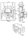
- the connecting plate 81 has the outline of an inverted drop and has a pair of pins 82a, 82b extending from the rear, which can be inserted into recesses in a wooden column 71 (FIG. 13). From the front protrudes a semicircular and L-shaped wreath 83, the free leg 84 pointing into the interior of the semicircle extends parallel to the front surface of the connection plate 81 at a distance d to be explained.
- the base 85 of the ring 83 connected to the front side of the connecting plate 81 carries three teeth or pins 87, 88, 89 at the lowest point on the inside thereof in an arrangement symmetrical to the vertical. The teeth rise up from the bottom of the base 85, have a trapezoidal cross section and completely fill the inner width of the ring 83 except for a front section 26.
- the carrier element 66 consists of a disc with external teeth 76, the spacing of which is selected such that the external teeth 76 fit smoothly between the teeth or pins 87, 88, 89 (FIGS. 1, 2) of the ring 83 and the teeth or pins in the Recessing space between the teeth 76 are appropriately recorded.
- the carrier disk 66 is fastened to the support bracket 67 via a spacer 68, which is designed as a T-rail in this example and supports the goods base 70.
- the thickness of the carrier plate 66 is substantially equal to the distance d between the leg 84 and the front side of the connecting plate 81 and the thickness of the spacer 68 is greater than the wall thickness of the leg 84.
- the carrier plate 66 with the support angle 67 and product base 70 can be inserted into the collar 83 can be hooked in and fixed in any inclination about an axis passing through the center of the arc of a circle by engagement of the external teeth 76 with the teeth 87, 88, 89.
- the outer teeth 76 remain hidden behind a flange 28 which runs around the edge of the periphery of the carrier disk 66 facing the goods base 70 and which has the same height as the outer teeth and a somewhat smaller thickness than the width of the front section 26.
- leg 84 is omitted in this embodiment, the result is a device that can be manufactured much cheaper compared to the arrangement described in DE-A-27 39 147, without losing the universality with respect to the selectable and adjustable angle of inclination.
- the carrier disk 66 can be a commercially available gear, for example, and the teeth 87, 88, 89 with the base 85 can also be produced very easily using prefabricated components.
- this embodiment of the invention enables the axial fixation of the carrier disk 66 on the connecting plate 81 even when the product base 70 is subjected to high loads without impairing the choice of the inclination angle of the product base 70.
- FIG. 5 shows the use of an upwardly tapering mandrel or pin 80 instead of the tooth 88, which is arranged in the center of the base 85. Teeth 87 and 89 are omitted. Likewise, the leg 84 is missing, and only the angular sections 90, 91 are provided to prevent the carrier disk 66 from tilting. According to FIG. 6, the latter has no outer teeth on the smooth circumference, but is instead provided with bores 93 which allow the carrier disk 66 to be pushed onto the mandrel 80 in a selectable inclination of the product base 70. Otherwise, this embodiment of the invention corresponds to that shown in FIGS. 1-4.
- connection plate 81 has on its front side an upwardly open, polygonal recess 100 as a pan-shaped support device, the support element 66 consists of a circular disk with a polygonal outline and the connection plate is in one in the Column 71 inserted U-rail.
- the U-rail 94 which is embedded over the entire height of the column on the side pointing in the longitudinal direction of the goods base 70, has on its rear side a plurality of holes 95 arranged one above the other in a row with the same spacing, into which holes on the rear side of the connection plate 81 trained angle hooks can be hung.
- each angle hook 96 engages behind the lower edge of each hole 95 when the connection plate 81 is suspended, the suspended connection plate 81 is secured against axial movement in the U-rail 94.
- the same effect results if each pin 82a, 82b is provided with an undercut 130 on the lower peripheral section directly on the rear side of the connection plate 81.
- ribs 57, 58 act as a union.
- the carrier disk 66 has a circumferential groove 59, in which the ribs 57, 58 engage.
- a circumferential, radially projecting strip 56 is formed on the rear side of the carrier disk 66 by the circumferential groove, which engages behind the ribs 57, 58 at any angle after the carrier disk 66 has been inserted into the connecting plate 81. Since the strip 56 itself consists of several polygon-like sections, two opposite sections of the strip 56 engage behind the mutually opposite ribs 57, 58. In FIG. 8, two angular positions of the carrier disk 66 are shown by dash-dotted lines indicating the contact angle. In one position the support angle is horizontal, in the second position shown the support angle inserted into a front recess 55 of the carrier disk 66 tilts downward to the right. In both positions, different, opposite sections of the strip 56 on the carrier disk 66 engage behind the ribs 57, 58.
- polygon surfaces 98, 99 each have an inwardly projecting step 102, 104 on their section pointing away from the front of the back plate 97, which narrow the opening of the connection plate 81.
- Each of the two steps 102, 104 merges into the rear base section 106, 107 via an inclined surface 108.
- the carrier disk 66 has a front polygon section 110 with a smaller diameter, to which an edge 101 which projects radially over an oblique transition surface 105 is connected to the rear.
- the edge 101 has an outer diameter that is slightly smaller than the inside diameter of the connecting plate 81 measured between the base sections 106, 107, while the radial extent of the front section 110 of the carrier disk 66 is smaller than the inside diameter between the steps 102, 104 of the Sub-base.
- the edge 101 engages behind the steps 102, 104, the inclined transition surface 105 abutting the inclined surfaces 108.
- This embodiment also allows the carrier disk to be used at any angle specified by the polygon surfaces. Furthermore, the space available between opposing columns 71 is used for the goods storage 70.
- the axial locking of the carrier disk 66 is achieved by means of wedge surfaces.
- the polygonal surfaces rise uniformly outwards, so that the inclined surfaces 108 as conical surfaces 117 extend over the entire depth of the polygonal surfaces.
- the carrier disk is designed as a polygon cone with polygon surfaces 115 extending radially inwards.
- connection plate consists of a rosette 112 which is screwed into a bore 116 of the column 71 with a rear external thread ring 114.
- the rosette also has a front tooth plate, in the central opening 120 of which a plurality of teeth 122 protrude inwards.
- the support element is placed as a hook 124 butt on the support bracket 67. Its lower end pointing away from the support angle 67 is extended downwards to a nose 126. On the upper edge, the hook has a plate 128 which extends at least such a distance from the support angle 67 that its edge pointing away from the latter lies over the front edge of the nose 126. The length of the plate 128 in the direction of the support angle 67 is slightly less than the distance between the crowns of the two opposite teeth 122a, 122b. In plan view of the support bracket 67, the carrier element with plate 128 thus forms a T, which is hatched in FIG. 12.
- a spring element 123, 125 can be riveted to the top of the plate 128 on both opposite sides, which spring element extends inwards at the free end (FIG. 12).
- the spring elements 123 and 125 are omitted for a better overview.
- the product base 70 is suspended in the connection plate with the support element fastened transversely to the support angle 67, so that the lug 126 engages in the bore 116 behind the connection plate 112.
- the side edges of the plate 128 then lie against the opposing teeth 122a, 122b and secure the goods base against tipping about the longitudinal axis.
- the carrier element can be suspended between other teeth, for example the neighboring teeth 122c, 122d.
Landscapes
- Assembled Shelves (AREA)
- Display Racks (AREA)
- Freezers Or Refrigerated Showcases (AREA)
- Vending Machines For Individual Products (AREA)
Claims (11)
Priority Applications (1)
| Application Number | Priority Date | Filing Date | Title |
|---|---|---|---|
| AT79101505T ATE1363T1 (de) | 1978-05-17 | 1979-05-17 | Vorrichtung zum loesbaren verankern einer warenablage an einer saeule eines inneneinrichtungssystems. |
Applications Claiming Priority (2)
| Application Number | Priority Date | Filing Date | Title |
|---|---|---|---|
| DE2821470 | 1978-05-17 | ||
| DE2821470A DE2821470C3 (de) | 1978-05-17 | 1978-05-17 | Vorrichtung zum lösbaren Verankern einer Warenablage an einer Säule eines Inneneinrichtung |
Publications (3)
| Publication Number | Publication Date |
|---|---|
| EP0005544A2 EP0005544A2 (fr) | 1979-11-28 |
| EP0005544A3 EP0005544A3 (en) | 1979-12-12 |
| EP0005544B1 true EP0005544B1 (fr) | 1982-07-28 |
Family
ID=6039529
Family Applications (1)
| Application Number | Title | Priority Date | Filing Date |
|---|---|---|---|
| EP79101505A Expired EP0005544B1 (fr) | 1978-05-17 | 1979-05-17 | Dispositif pour la fixation amovible d'une tablette à une colonne de présentoir |
Country Status (5)
| Country | Link |
|---|---|
| US (1) | US4314685A (fr) |
| EP (1) | EP0005544B1 (fr) |
| JP (1) | JPS558793A (fr) |
| AT (1) | ATE1363T1 (fr) |
| DE (1) | DE2821470C3 (fr) |
Families Citing this family (19)
| Publication number | Priority date | Publication date | Assignee | Title |
|---|---|---|---|---|
| JPS5122753A (ja) * | 1974-08-16 | 1976-02-23 | Sumitomo Chemical Co | Jushisoseibutsu |
| US4434722A (en) | 1981-05-22 | 1984-03-06 | Am Fab, Inc. | Tilt support for overbed table top and vertical lock assembly therefor |
| US4620684A (en) * | 1984-12-28 | 1986-11-04 | Coin Acceptors, Inc. | Support bracket assembly |
| US4798413A (en) * | 1985-10-17 | 1989-01-17 | Capelli Edward J | Tray device |
| US4929116A (en) * | 1988-03-31 | 1990-05-29 | Chesapeake Display And Packaging Company | Coupler assembly for connecting corrugated sheet material |
| US5090579A (en) * | 1990-09-20 | 1992-02-25 | Major Ronald P | Modular shelving system |
| US5205222A (en) * | 1992-06-04 | 1993-04-27 | Bernard Ronald V | Counter attachable ironing board |
| US5460345A (en) * | 1993-10-05 | 1995-10-24 | Trevola Holdings Pty Ltd | Adjustable merchandise display system |
| US6123033A (en) * | 1999-01-05 | 2000-09-26 | Patagonia, Inc. | Shelving system |
| US20110049070A1 (en) * | 2009-08-25 | 2011-03-03 | Patrick Sweeney | Portable Shelf System |
| US20130106270A1 (en) * | 2011-11-02 | 2013-05-02 | Da-sen Lin | Tool Stand |
| US10702085B1 (en) * | 2013-12-19 | 2020-07-07 | Deck Dressings, Llc. | Deck curtain system and method of use |
| TWI586246B (zh) * | 2014-03-05 | 2017-06-01 | 陳正基 | 壁掛結構 |
| CN105589521A (zh) * | 2014-11-18 | 2016-05-18 | 英业达科技有限公司 | 支撑组件 |
| EP3413761A1 (fr) * | 2016-02-08 | 2018-12-19 | 3M Innovative Properties Company | Appareil rotatif pour monter un article |
| US20190316620A1 (en) * | 2017-03-22 | 2019-10-17 | Chung Kwo Tzuo | Male pin and female housing set for a display stand, with a quick-engagement attachment system |
| US10413056B2 (en) * | 2017-04-28 | 2019-09-17 | Mills Display Limited | Shelving post and an adjustable shelving system |
| US10905260B2 (en) * | 2018-10-15 | 2021-02-02 | Westrock Shared Services, Llc | Display hutch |
| BR102019005089A2 (pt) * | 2019-03-15 | 2020-10-06 | Chung Kwo Tzuo | Conjunto de pino macho e alojamento fêmea para encaixe axial de prateleiras em paredes angulares, sinuosas e de geometrias variáveis de displays expositores |
Family Cites Families (12)
| Publication number | Priority date | Publication date | Assignee | Title |
|---|---|---|---|---|
| GB593204A (en) * | 1945-06-06 | 1947-10-10 | Henry Archibald Prior | Improvements in appliances having shelves, trays or racks for displaying or holding vendible commodities or other articles |
| CA659343A (en) * | 1963-03-12 | Firma Karl Steiner | Shelf rack | |
| FR1232330A (fr) * | 1958-09-28 | 1960-10-06 | Pied correctif de déclivité | |
| NL107523C (fr) * | 1959-04-28 | |||
| FR1338324A (fr) * | 1962-03-22 | 1963-09-27 | Dispositif de fixation de deux pièces l'une à l'autre | |
| FR2058795A5 (fr) * | 1969-09-26 | 1971-05-28 | Georcandas Constantin | |
| US3700114A (en) * | 1971-01-18 | 1972-10-24 | Clark Equipment Co | Adjustable shelf support bracket |
| FR2192452A5 (fr) * | 1972-07-07 | 1974-02-08 | Peronnet Jean C Aude | |
| US3795379A (en) * | 1972-09-13 | 1974-03-05 | Ebsco Ind Inc | Adjustable shelf support |
| JPS5129207U (fr) * | 1974-08-27 | 1976-03-03 | ||
| DE2501349C2 (de) * | 1975-01-15 | 1984-12-13 | Erich 2800 Bremen Schwan | Inneneinrichtungssystem |
| DE2739147A1 (de) * | 1977-08-31 | 1979-03-15 | Erich Schwan | Inneneinrichtungssystem fuer laeden u.dgl. |
-
1978
- 1978-05-17 DE DE2821470A patent/DE2821470C3/de not_active Expired
-
1979
- 1979-05-16 US US06/039,519 patent/US4314685A/en not_active Expired - Lifetime
- 1979-05-17 AT AT79101505T patent/ATE1363T1/de not_active IP Right Cessation
- 1979-05-17 JP JP6094679A patent/JPS558793A/ja active Pending
- 1979-05-17 EP EP79101505A patent/EP0005544B1/fr not_active Expired
Also Published As
| Publication number | Publication date |
|---|---|
| DE2821470C3 (de) | 1981-03-19 |
| ATE1363T1 (de) | 1982-08-15 |
| DE2821470B2 (de) | 1980-08-07 |
| US4314685A (en) | 1982-02-09 |
| EP0005544A3 (en) | 1979-12-12 |
| DE2821470A1 (de) | 1979-11-22 |
| EP0005544A2 (fr) | 1979-11-28 |
| JPS558793A (en) | 1980-01-22 |
Similar Documents
| Publication | Publication Date | Title |
|---|---|---|
| EP0005544B1 (fr) | Dispositif pour la fixation amovible d'une tablette à une colonne de présentoir | |
| DE3824984C2 (de) | Regalboden-Tragsystem mit einem Tragpfosten mit dreieckförmigem Querschnitt | |
| DE60212812T2 (de) | Vertikal stabilisierte regalbügelgruppe | |
| DE69520595T2 (de) | Warenträgersystem | |
| DE1805523A1 (de) | Stuetzanordnung fuer Fachbretter od.dgl. | |
| DE9301716U1 (de) | Zusammensetzbares Gestell | |
| EP0404725B1 (fr) | Dispositif de présentation d'articles avec consoles réglables en hauteur dans un agencement mural ou en colonnes | |
| DE3925302C2 (fr) | ||
| DE2557966A1 (de) | Bodentraeger | |
| DE4332437C2 (de) | Tisch und Tischsystem | |
| DE4115707A1 (de) | Foerdereinrichtung | |
| EP0040180B1 (fr) | Tréteau de montage | |
| DE4421690A1 (de) | Variables Warenpräsentations- und Aufnahmesystem | |
| DE3601230C2 (fr) | ||
| DE4114378C2 (fr) | ||
| DE19537364C1 (de) | Möbelsystem | |
| DE7814774U1 (de) | Vorrichtung zum loesbaren verankern einer warenablage an einer saeule eines inneneinrichtungssystems | |
| WO2019166421A1 (fr) | Système de fixation d'un objet sur un support | |
| DE19617551B4 (de) | Wannenträger | |
| DE2549352A1 (de) | Montageelement fuer moebelscharniere | |
| DE3742019C2 (fr) | ||
| DE3127187C2 (de) | Regal für Bücher | |
| DE3130218A1 (de) | "schaukelgrill" | |
| DE2006942C (de) | Möbel mit mindestens einem Träger oder Tragarm, der an einer seiner Seiten mit einem aufrecht angeordneten Möbelteil leicht lösbar verbunden ist | |
| DE20012148U1 (de) | Glasbodenhalter |
Legal Events
| Date | Code | Title | Description |
|---|---|---|---|
| PUAI | Public reference made under article 153(3) epc to a published international application that has entered the european phase |
Free format text: ORIGINAL CODE: 0009012 |
|
| PUAL | Search report despatched |
Free format text: ORIGINAL CODE: 0009013 |
|
| AK | Designated contracting states |
Designated state(s): AT BE CH FR GB IT NL SE |
|
| AK | Designated contracting states |
Designated state(s): AT BE CH FR GB IT NL SE |
|
| 17P | Request for examination filed | ||
| ITF | It: translation for a ep patent filed | ||
| GRAA | (expected) grant |
Free format text: ORIGINAL CODE: 0009210 |
|
| AK | Designated contracting states |
Designated state(s): AT BE CH FR GB IT NL SE |
|
| REF | Corresponds to: |
Ref document number: 1363 Country of ref document: AT Date of ref document: 19820815 Kind code of ref document: T |
|
| ET | Fr: translation filed | ||
| PGFP | Annual fee paid to national office [announced via postgrant information from national office to epo] |
Ref country code: FR Payment date: 19890517 Year of fee payment: 11 |
|
| PGFP | Annual fee paid to national office [announced via postgrant information from national office to epo] |
Ref country code: SE Payment date: 19890523 Year of fee payment: 11 |
|
| PGFP | Annual fee paid to national office [announced via postgrant information from national office to epo] |
Ref country code: AT Payment date: 19890526 Year of fee payment: 11 |
|
| ITTA | It: last paid annual fee | ||
| PGFP | Annual fee paid to national office [announced via postgrant information from national office to epo] |
Ref country code: NL Payment date: 19890531 Year of fee payment: 11 Ref country code: GB Payment date: 19890531 Year of fee payment: 11 |
|
| PGFP | Annual fee paid to national office [announced via postgrant information from national office to epo] |
Ref country code: BE Payment date: 19890706 Year of fee payment: 11 |
|
| PGFP | Annual fee paid to national office [announced via postgrant information from national office to epo] |
Ref country code: CH Payment date: 19890821 Year of fee payment: 11 |
|
| PG25 | Lapsed in a contracting state [announced via postgrant information from national office to epo] |
Ref country code: GB Effective date: 19900517 Ref country code: AT Effective date: 19900517 |
|
| PG25 | Lapsed in a contracting state [announced via postgrant information from national office to epo] |
Ref country code: SE Effective date: 19900518 |
|
| PG25 | Lapsed in a contracting state [announced via postgrant information from national office to epo] |
Ref country code: CH Effective date: 19900531 Ref country code: BE Effective date: 19900531 |
|
| BERE | Be: lapsed |
Owner name: HUWIL G.M.B.H. MOBELSCHLOSS- U. BESCHLAGFABRIKEN Effective date: 19900531 Owner name: SCHWAN ERICH Effective date: 19900531 |
|
| PG25 | Lapsed in a contracting state [announced via postgrant information from national office to epo] |
Ref country code: NL Effective date: 19901201 |
|
| GBPC | Gb: european patent ceased through non-payment of renewal fee | ||
| NLV4 | Nl: lapsed or anulled due to non-payment of the annual fee | ||
| PG25 | Lapsed in a contracting state [announced via postgrant information from national office to epo] |
Ref country code: FR Effective date: 19910131 |
|
| REG | Reference to a national code |
Ref country code: CH Ref legal event code: PL |
|
| REG | Reference to a national code |
Ref country code: FR Ref legal event code: ST |
|
| EUG | Se: european patent has lapsed |
Ref document number: 79101505.0 Effective date: 19910114 |
|
| PLBE | No opposition filed within time limit |
Free format text: ORIGINAL CODE: 0009261 |
|
| STAA | Information on the status of an ep patent application or granted ep patent |
Free format text: STATUS: NO OPPOSITION FILED WITHIN TIME LIMIT |