EP0040180B1 - Tréteau de montage - Google Patents
Tréteau de montage Download PDFInfo
- Publication number
- EP0040180B1 EP0040180B1 EP81810183A EP81810183A EP0040180B1 EP 0040180 B1 EP0040180 B1 EP 0040180B1 EP 81810183 A EP81810183 A EP 81810183A EP 81810183 A EP81810183 A EP 81810183A EP 0040180 B1 EP0040180 B1 EP 0040180B1
- Authority
- EP
- European Patent Office
- Prior art keywords
- holder
- teeth
- grooves
- side wall
- support
- Prior art date
- Legal status (The legal status is an assumption and is not a legal conclusion. Google has not performed a legal analysis and makes no representation as to the accuracy of the status listed.)
- Expired
Links
- 239000000725 suspension Substances 0.000 claims 2
- 230000000284 resting effect Effects 0.000 claims 1
- 230000006835 compression Effects 0.000 description 11
- 238000007906 compression Methods 0.000 description 11
- 241000282461 Canis lupus Species 0.000 description 2
- 238000006073 displacement reaction Methods 0.000 description 1
- 230000007704 transition Effects 0.000 description 1
Images

Classifications
-
- A—HUMAN NECESSITIES
- A47—FURNITURE; DOMESTIC ARTICLES OR APPLIANCES; COFFEE MILLS; SPICE MILLS; SUCTION CLEANERS IN GENERAL
- A47B—TABLES; DESKS; OFFICE FURNITURE; CABINETS; DRAWERS; GENERAL DETAILS OF FURNITURE
- A47B57/00—Cabinets, racks or shelf units, characterised by features for adjusting shelves or partitions
- A47B57/30—Cabinets, racks or shelf units, characterised by features for adjusting shelves or partitions with means for adjusting the height of detachable shelf supports
- A47B57/54—Cabinets, racks or shelf units, characterised by features for adjusting shelves or partitions with means for adjusting the height of detachable shelf supports consisting of clamping means, e.g. with sliding bolts or sliding wedges
- A47B57/56—Cabinets, racks or shelf units, characterised by features for adjusting shelves or partitions with means for adjusting the height of detachable shelf supports consisting of clamping means, e.g. with sliding bolts or sliding wedges the shelf supports being cantilever brackets
- A47B57/565—Cabinets, racks or shelf units, characterised by features for adjusting shelves or partitions with means for adjusting the height of detachable shelf supports consisting of clamping means, e.g. with sliding bolts or sliding wedges the shelf supports being cantilever brackets using screw means
Definitions
- the invention relates to an assembly frame with a vertical stand consisting of a rectangular hollow profile, on the side wall of which at least one flange provided with a horizontal support is height-adjustable and clampable by means of a clamping device, wherein a longitudinal slot is left in the side wall of the support. whose inwardly bent edges each have an inward toothing into which an insertable through the slot and rotatable by 90 ° rotatable holder of the clamping device engages, furthermore a spring-loaded, tensionable clamping member is arranged on the holder, which is connected to the carrier and the Flange of the same presses against the side wall of the stand.
- Such a frame is known from US-A-2 696 139.
- the inner walls of the grooves are provided with teeth facing each other, which are offset from one another. When the carrier is clamped, the teeth bite into the inwardly bent edges of the support profile in order to create a secure, immovable connection.
- Simple height adjustment is also not possible here, and the teeth are subject to wear.
- the contact pressure initially exerted by tightening the fastening nut in the area of the serrations can decrease as a result of material fatigue.
- the carrier is poorly guided in the hollow profile and can tilt during adjustment.
- DE-B-1 298 253 shows a distant prior art in which a horizontal shelf support is attached to a vertical hollow profile.
- a T-shaped stop in the form of a bolt is provided, the head of which abuts the inside of the flange of the vertical hollow profile.
- the adjacent surfaces of the head and the flange can be provided with horizontal, interlocking ribs.
- this frame also has the same disadvantages as the two frames already mentioned above.
- the invention is based on the object of designing an assembly frame of the type described in the introduction in such a way that the disadvantages of the known frames are avoided. It should therefore be possible to adjust the clamping device effortlessly and without the risk that the carrier unintentionally loosens when fastening or adjusting the carrier and to relieve the teeth of the stand from the contact pressure of the holder.
- the holder has two parallel grooves in which the toothed longitudinal edges of the slot are guided with play, that at least one catch is arranged in each of the grooves and engages in the toothing, and that the two surface areas of the holder lying laterally outside of the grooves are designed as flat pressure surfaces which transmit the contact pressure to the stator side wall while relieving pressure on the catches and the serrations.
- the middle part of the holder located between the grooves can protrude into the longitudinal slot.
- the catches can be locking pins that pass through the grooves transversely.
- the holder with its central part located between the grooves, engages relatively far into the longitudinal slot, which is delimited by the longitudinal longitudinal edges of the upright, which have the serrations.
- the holder is guided in its correct orientation and secured against rotation, since it can practically never inadvertently slide inwards even with a loose fastening nut by appropriate adjustment of the spring play, so that both locking pins disengage from the tooth gaps at the same time. Therefore, the clamping device with the carrier can be attached or adjusted practically effortlessly at the desired height, and inadvertent loosening of the carrier is practically impossible with all manipulations.
- the teeth of the stand are designed in the manner of saw or wolf teeth, the long tooth flanks of which are inclined obliquely upwards from the tooth base and the short tooth flanks of which are essentially horizontally or slightly downwardly inclined and a concave curve at the transition to the tooth base for secure engagement of the teeth Have locking pins.
- the tooth profile shape forms a safety toothing in the assembly frame according to the invention, which allows problem-free, secure engagement, adjustment and fixing of the carrier at any height.
- the carrier can be adjusted upwards by simple displacement, the fastening nut only having to be loosened so far that the holder with the threaded bolt can slide inwards in the axial direction of the threaded bolt against the action of the compression spring when the locking pins slide on a long tooth flank, until the locking pins have passed the tooth tip concerned, whereupon the holder automatically engages in the following tooth gaps.
- the fastening nut can have an integrally formed ring flange on its inside with an annular groove receiving the outer end of the compression spring in the manner of a spring sleeve, whereby it is reliably avoided that the spring end is pressed into the screw thread.
- the mounting frame according to the invention is preferably, as mentioned at the outset, equipped with so-called hanging supports as stands and is therefore intended for attachment to a ceiling or a ceiling structure for the laying of lines, pipes or the like, but it can also be easily anchored to the floor to have.
- the mounting frame can be used as a shelf, the horizontal supports carrying the shelves or plates.
- the stands on opposite sides can each have a longitudinal slot with corresponding, inwardly oriented serrations, so that supports can be attached either on one or the other side or on both sides.
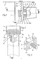
- the mounting frame has a vertical stand 1 in the form of a hanging pole with an upper horizontal fastening flange 2 (FIG. 1), which is fastened to a ceiling structure.
- the stand 1 which therefore hangs from the ceiling without leaning on the floor, consists of a substantially rectangular hollow profile (FIG. 2) with a central longitudinal slot 3 provided on its one long side wall, the longitudinal edges of which are bent inwards at a right angle and are provided with an inward toothing 4 (Fig. 1).
- a horizontal support 5 with a vertical fastening flange 6, which has at least one opening 7, can be detachably attached and its height adjustable.
- a clamping device with a threaded bolt 8, a holder 9, which is rigidly attached to one end of the threaded bolt 8, a pressure piece 12, which sits loosely on the threaded bolt, a fastening nut 13 screwed onto the other end thereof and one between the latter and the pressure piece 12 arranged, surrounding the threaded bolt 8 compression spring 14.
- the clamping device is arranged so that the threaded bolt 8 passes through the opening 7 provided in the mounting flange 6 of the support 5 and the longitudinal slot 3 and at its inner end carries the holder 9 located within the hollow stator profile, while the pressure piece 12 and the fastening nut 13 sit on the outer area of the threaded bolt 8.
- the holder 9 is a block-shaped part (Fig. 3), the transverse dimension of which is greater than the width of the longitudinal slot 3, and has on its outwardly facing surface two parallel grooves 10 which are oriented vertically in the correct mounting position and are thus arranged and dimensioned that the longitudinal edges can engage with their serrations 4 with play in these grooves 10 (Fig. 2).
- Each of the two grooves 10 is traversed in the transverse direction by two parallel locking pins 11, the distance between which in the example considered is twice the distance between the teeth of the toothings 4, so that both locking pins 11 can engage in tooth gaps at the same time.
- the holder 9 since the central region of the holder 9 between the grooves 10 engages relatively far from the inside into the longitudinal slot 3 delimited by the toothings 4, the holder 9 is guided well, and appropriate adjustment of the play of the compression spring 14 can practically be prevented with certainty that the holder 9 is inadvertently moved inwards even when the connection is loose, that both locking pins 11 could slide out of the teeth 4 at the same time, causing the support 5 to slide off and the holder 9 to be rotated out of its correct fastening position.
- the serrations 4 are designed as safety serrations in the form of saw or wolf teeth, the long tooth flanks 4a of which are directed obliquely upwards, while the short tooth flanks are essentially horizontal or slightly inclined downwards and concave at the tooth base rounded tooth gaps 4b pass into which the locking pins 11 can securely engage in their fastening position.
- This tooth profile also allows a problem-free height adjustment of the carrier 5, in that it only needs to be moved upwards after the fastening nut 13 has been loosened slightly, the locking pins 11 compressing the compression spring 14 and correspondingly displacing the holder 9 inwards along the tooth flanks slide, as shown in Fig. 4, and engage automatically in the following tooth gaps.
- the pressure piece 12 In order to secure the position of the compression spring 14, the pressure piece 12, as shown in FIG. 1, is designed as a spring sleeve receiving the inner spring end, while an annular flange 13a is formed on the inside of the fastening nut 13, which annular groove receives the outer spring end , also in the manner of a spring sleeve, limited.
- the invention is not limited to the exemplary embodiment described, but rather allows for numerous variants with regard to the design of the individual components.
- the stand 1 can also be a stand to be anchored to the floor.
- the stand can be designed such that it has longitudinal slots with corresponding serrations on two opposite sides so that supports 5 can be attached to both sides of the stand.
Landscapes
- Clamps And Clips (AREA)
- Input Circuits Of Receivers And Coupling Of Receivers And Audio Equipment (AREA)
- Non-Reversible Transmitting Devices (AREA)
- Piezo-Electric Or Mechanical Vibrators, Or Delay Or Filter Circuits (AREA)
- Mutual Connection Of Rods And Tubes (AREA)
Claims (8)
Priority Applications (1)
| Application Number | Priority Date | Filing Date | Title |
|---|---|---|---|
| AT81810183T ATE5046T1 (de) | 1980-05-13 | 1981-05-12 | Montagegestell. |
Applications Claiming Priority (2)
| Application Number | Priority Date | Filing Date | Title |
|---|---|---|---|
| CH372380 | 1980-05-13 | ||
| CH3723/80 | 1980-05-13 |
Publications (2)
| Publication Number | Publication Date |
|---|---|
| EP0040180A1 EP0040180A1 (fr) | 1981-11-18 |
| EP0040180B1 true EP0040180B1 (fr) | 1983-10-19 |
Family
ID=4262112
Family Applications (1)
| Application Number | Title | Priority Date | Filing Date |
|---|---|---|---|
| EP81810183A Expired EP0040180B1 (fr) | 1980-05-13 | 1981-05-12 | Tréteau de montage |
Country Status (3)
| Country | Link |
|---|---|
| EP (1) | EP0040180B1 (fr) |
| AT (1) | ATE5046T1 (fr) |
| DE (1) | DE3161234D1 (fr) |
Cited By (1)
| Publication number | Priority date | Publication date | Assignee | Title |
|---|---|---|---|---|
| CN106461314A (zh) * | 2014-08-01 | 2017-02-22 | Bsh家用电器有限公司 | 包括支撑基底和支撑轨的冷却装置 |
Families Citing this family (6)
| Publication number | Priority date | Publication date | Assignee | Title |
|---|---|---|---|---|
| DE3701530A1 (de) * | 1987-01-21 | 1988-08-04 | Fricker Siegfried | Gezahnte ankerschiene |
| DE29821154U1 (de) * | 1998-11-26 | 1999-09-30 | Erbslöh AG, 42553 Velbert | Halbhohlprofil mit einem längs des Hohlprofils verschiebbaren Verbindungselement |
| KR20080094363A (ko) * | 2007-04-20 | 2008-10-23 | 엘지전자 주식회사 | 선반의 높이 조절 구조 및 이를 갖는 냉장고 |
| CN202817510U (zh) * | 2009-04-29 | 2013-03-20 | Abb公司 | 连接组件和母线连接结构 |
| CN110893606B (zh) * | 2018-09-13 | 2022-12-20 | 中车株洲电力机车研究所有限公司 | 一种液压扳手托举装置 |
| IT202100011945A1 (it) * | 2021-05-10 | 2022-11-10 | Rheavendors Ind S P A | Distributore automatico di bevande |
Family Cites Families (6)
| Publication number | Priority date | Publication date | Assignee | Title |
|---|---|---|---|---|
| US2696139A (en) * | 1952-05-28 | 1954-12-07 | Charles W Attwood | Nut for locking engagement with unistrut |
| US2767951A (en) * | 1953-11-06 | 1956-10-23 | Ex Corp | Shelf lock |
| DE1298253B (de) * | 1966-03-21 | 1969-06-26 | Sachau Helmuth Heinrich | Fachbodentraeger mit Klemmvorrichtung zur Hoehenverstellung an einem Hohlprofilpfosten |
| US3828516A (en) * | 1971-11-24 | 1974-08-13 | Wieland Werke Ag | Press-fitted joint between a transom bar and a frame or sash bar for use on windows, doors or the like |
| FR2320493A1 (fr) * | 1975-08-04 | 1977-03-04 | Lemoine Christian | Dispositif de support a longeron profile, et banc de travail realise par mise en oeuvre du dispositif |
| DE2630766A1 (de) * | 1976-07-08 | 1978-01-12 | Maurice Grosse | Vertikalschiene mit einhaengekonsolen fuer moebel oder dergleichen |
-
1981
- 1981-05-12 AT AT81810183T patent/ATE5046T1/de not_active IP Right Cessation
- 1981-05-12 EP EP81810183A patent/EP0040180B1/fr not_active Expired
- 1981-05-12 DE DE8181810183T patent/DE3161234D1/de not_active Expired
Cited By (2)
| Publication number | Priority date | Publication date | Assignee | Title |
|---|---|---|---|---|
| CN106461314A (zh) * | 2014-08-01 | 2017-02-22 | Bsh家用电器有限公司 | 包括支撑基底和支撑轨的冷却装置 |
| CN106461314B (zh) * | 2014-08-01 | 2019-05-14 | Bsh家用电器有限公司 | 包括支撑基底和支撑轨的冷却装置 |
Also Published As
| Publication number | Publication date |
|---|---|
| DE3161234D1 (en) | 1983-11-24 |
| ATE5046T1 (de) | 1983-11-15 |
| EP0040180A1 (fr) | 1981-11-18 |
Similar Documents
| Publication | Publication Date | Title |
|---|---|---|
| DE2618442C2 (de) | Stütze für ein Geländer oder dergleichen | |
| DE7514441U (de) | Einstellvorrichtung fuer verbindungselemente an stuetzpfosten von raumteilersystemen | |
| DE2455399C3 (de) | Einstellbare Laufrolleneinrichtung für Fenster, Türen o.dgl | |
| EP0005544B1 (fr) | Dispositif pour la fixation amovible d'une tablette à une colonne de présentoir | |
| DE3843658A1 (de) | Vorrichtung zur einstellung der frontblende bei schubladen | |
| DE1923669C3 (de) | Verankerungsvorrichtung zum Befestigen von Gegenständen | |
| DE3004313A1 (de) | Topfscharnier | |
| DE4332437C2 (de) | Tisch und Tischsystem | |
| EP1800563A1 (fr) | Console amovible pour étalages de vitrines | |
| EP0040180A1 (fr) | Tréteau de montage | |
| DE3218065C2 (de) | Gitterrost zur Abdeckung einer Einlauföffnung im Straßenbau | |
| DE4403927C2 (de) | Befestigungsvorrichtung für Bretter oder Regalbretter | |
| EP0417177B1 (fr) | Systeme de rayonnage | |
| DE2208116C3 (de) | Vorrichtung zum Befestigen und Nivellieren von Gegenständen | |
| DE29809994U1 (de) | Modular aufgebautes Tischgestell | |
| EP0144926A2 (fr) | Dispositif pour la fixation de caissons aux murs et/ou aux plafonds | |
| EP0383213B1 (fr) | Support de tablette d'étagère | |
| EP0826850A2 (fr) | Elément porteur pour façade | |
| DE8224861U1 (de) | Aus Profilteilen bestehendes Gestell | |
| DE2853714A1 (de) | Traggestell | |
| DE2216438A1 (de) | Fotografisches stativ | |
| AT502878B1 (de) | Schieberegalanlage | |
| EP3777615B1 (fr) | Lit réglable en hauteur | |
| DE3232766C1 (de) | Aus Profilteilen bestehendes Gestell | |
| DE3838506C2 (fr) |
Legal Events
| Date | Code | Title | Description |
|---|---|---|---|
| PUAI | Public reference made under article 153(3) epc to a published international application that has entered the european phase |
Free format text: ORIGINAL CODE: 0009012 |
|
| AK | Designated contracting states |
Designated state(s): AT BE CH DE FR GB IT LU NL SE |
|
| 17P | Request for examination filed |
Effective date: 19811204 |
|
| ITF | It: translation for a ep patent filed | ||
| GRAA | (expected) grant |
Free format text: ORIGINAL CODE: 0009210 |
|
| AK | Designated contracting states |
Designated state(s): AT BE CH DE FR GB IT LI LU NL SE |
|
| PG25 | Lapsed in a contracting state [announced via postgrant information from national office to epo] |
Ref country code: SE Effective date: 19831019 |
|
| REF | Corresponds to: |
Ref document number: 5046 Country of ref document: AT Date of ref document: 19831115 Kind code of ref document: T |
|
| REF | Corresponds to: |
Ref document number: 3161234 Country of ref document: DE Date of ref document: 19831124 |
|
| ET | Fr: translation filed | ||
| PG25 | Lapsed in a contracting state [announced via postgrant information from national office to epo] |
Ref country code: LU Free format text: LAPSE BECAUSE OF NON-PAYMENT OF DUE FEES Effective date: 19840531 |
|
| PLBE | No opposition filed within time limit |
Free format text: ORIGINAL CODE: 0009261 |
|
| STAA | Information on the status of an ep patent application or granted ep patent |
Free format text: STATUS: NO OPPOSITION FILED WITHIN TIME LIMIT |
|
| 26N | No opposition filed | ||
| ITTA | It: last paid annual fee | ||
| PGFP | Annual fee paid to national office [announced via postgrant information from national office to epo] |
Ref country code: FR Payment date: 19970411 Year of fee payment: 17 |
|
| PGFP | Annual fee paid to national office [announced via postgrant information from national office to epo] |
Ref country code: AT Payment date: 19970415 Year of fee payment: 17 |
|
| PGFP | Annual fee paid to national office [announced via postgrant information from national office to epo] |
Ref country code: GB Payment date: 19970417 Year of fee payment: 17 Ref country code: CH Payment date: 19970417 Year of fee payment: 17 |
|
| PGFP | Annual fee paid to national office [announced via postgrant information from national office to epo] |
Ref country code: DE Payment date: 19970423 Year of fee payment: 17 Ref country code: BE Payment date: 19970423 Year of fee payment: 17 |
|
| PGFP | Annual fee paid to national office [announced via postgrant information from national office to epo] |
Ref country code: NL Payment date: 19970529 Year of fee payment: 17 |
|
| PG25 | Lapsed in a contracting state [announced via postgrant information from national office to epo] |
Ref country code: GB Free format text: LAPSE BECAUSE OF NON-PAYMENT OF DUE FEES Effective date: 19980512 Ref country code: AT Free format text: LAPSE BECAUSE OF NON-PAYMENT OF DUE FEES Effective date: 19980512 |
|
| PG25 | Lapsed in a contracting state [announced via postgrant information from national office to epo] |
Ref country code: LI Free format text: LAPSE BECAUSE OF NON-PAYMENT OF DUE FEES Effective date: 19980531 Ref country code: FR Free format text: LAPSE BECAUSE OF NON-PAYMENT OF DUE FEES Effective date: 19980531 Ref country code: CH Free format text: LAPSE BECAUSE OF NON-PAYMENT OF DUE FEES Effective date: 19980531 Ref country code: BE Free format text: LAPSE BECAUSE OF NON-PAYMENT OF DUE FEES Effective date: 19980531 |
|
| BERE | Be: lapsed |
Owner name: EBO A.G. Effective date: 19980531 |
|
| PG25 | Lapsed in a contracting state [announced via postgrant information from national office to epo] |
Ref country code: NL Free format text: LAPSE BECAUSE OF NON-PAYMENT OF DUE FEES Effective date: 19981201 |
|
| GBPC | Gb: european patent ceased through non-payment of renewal fee |
Effective date: 19980512 |
|
| REG | Reference to a national code |
Ref country code: CH Ref legal event code: PL |
|
| NLV4 | Nl: lapsed or anulled due to non-payment of the annual fee |
Effective date: 19981201 |
|
| PG25 | Lapsed in a contracting state [announced via postgrant information from national office to epo] |
Ref country code: DE Free format text: LAPSE BECAUSE OF NON-PAYMENT OF DUE FEES Effective date: 19990302 |
|
| REG | Reference to a national code |
Ref country code: FR Ref legal event code: ST |