EP0006807B1 - Anordnung für eine multiplexierte Funkübertragung - Google Patents
Anordnung für eine multiplexierte Funkübertragung Download PDFInfo
- Publication number
- EP0006807B1 EP0006807B1 EP79400409A EP79400409A EP0006807B1 EP 0006807 B1 EP0006807 B1 EP 0006807B1 EP 79400409 A EP79400409 A EP 79400409A EP 79400409 A EP79400409 A EP 79400409A EP 0006807 B1 EP0006807 B1 EP 0006807B1
- Authority
- EP
- European Patent Office
- Prior art keywords
- frequency
- transmitter
- operator
- mhz
- low
- Prior art date
- Legal status (The legal status is an assumption and is not a legal conclusion. Google has not performed a legal analysis and makes no representation as to the accuracy of the status listed.)
- Expired
Links
- 230000005540 biological transmission Effects 0.000 claims description 5
- 238000010586 diagram Methods 0.000 description 6
- 230000003321 amplification Effects 0.000 description 3
- 238000003199 nucleic acid amplification method Methods 0.000 description 3
- 238000005202 decontamination Methods 0.000 description 2
- 230000003588 decontaminative effect Effects 0.000 description 2
- 235000021183 entrée Nutrition 0.000 description 2
- 239000010453 quartz Substances 0.000 description 2
- 230000035945 sensitivity Effects 0.000 description 2
- VYPSYNLAJGMNEJ-UHFFFAOYSA-N silicon dioxide Inorganic materials O=[Si]=O VYPSYNLAJGMNEJ-UHFFFAOYSA-N 0.000 description 2
- 241001080024 Telles Species 0.000 description 1
- 238000010276 construction Methods 0.000 description 1
- 238000001514 detection method Methods 0.000 description 1
- 239000000463 material Substances 0.000 description 1
- 230000002285 radioactive effect Effects 0.000 description 1
Images

Classifications
-
- H—ELECTRICITY
- H04—ELECTRIC COMMUNICATION TECHNIQUE
- H04B—TRANSMISSION
- H04B7/00—Radio transmission systems, i.e. using radiation field
- H04B7/24—Radio transmission systems, i.e. using radiation field for communication between two or more posts
Definitions
- the present invention relates to a multiplex radio link device. It finds a general application in telecommunications and a particular application in the realization of means of phonic communication between several people distant from each other, or isolated from each other by the fact that they are covered with waterproof suits, which is the This is particularly the case for people working in hostile environments and, in particular, in decontamination chambers for radioactive objects and materials.
- the wire connection devices are generally not satisfactory in this application, due to the permanent risks of cutting the wires, and the poor quality of the connection.
- a wireless link system is used, by radio wave.
- Such a system is composed of a set of transceiver stations, each operator having at his disposal such a station, hereinafter called operator station, and the person located outside the enclosure having another post then said post-director.
- operator station each operator having at his disposal such a station
- manager station the person located outside the enclosure having another post then said post-director.
- each of the communication channels established between an operator station and the manager station can be carried out on a particular frequency, in order to avoid interference between messages originating from several operators. We then obtain a frequency multiplexed system.
- the manager station be equipped with as many receivers as there are operator stations, each of said receivers working on a particular frequency; the station manager can be fitted with as many transmitters as there are operator stations, but it is also possible to use only one transmitter, the receivers of the operator stations then being all identical.
- the subject of the invention is precisely a device of the type described, but which also gives operators the possibility of communicating between them without the need to add additional means to the operator stations.
- the device of the invention De requires on the part of said operators no manipulation of switching members, in particular during the passages between a reception phase and a transmission phase.
- the subject of the present invention is a frequency-multiplexed radio link device between a manager and at least two operator stations, this device being of the type in which the manager includes, on the one hand, a transmitter receiving a low frequency signal from a microphone and emitting a high frequency wave Fe and, on the other hand, as many receivers as there are operator stations, each receiver being tuned to a high frequency particular Fi different from Fe, each receiver delivering a low frequency signal which is directed towards a loudspeaker, and in which each post-operator comprises, on the one hand, a receiver calibrated on said frequency Fe and feeding a loudspeaker and, on the other hand, a transmitter connected to a microphone and operating on one of said frequencies Fi, characterized in that the director station comprises a transmitter consisting of a low frequency preamplification stage connected to the microph one then modulation and amplification means connected to an antenna and in that it further comprises means for taking a portion of the low frequency signals delivered by each of the receivers of this manager and re-injecting these
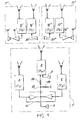
- Figure 1 refers by way of explanation to the particular case where the number of these operator positions is equal to two.
- the device shown comprises two operator stations P 'and P "and a director station P.
- the latter comprises, on the one hand, a transmitter 2 which receives a low frequency signal from a microphone 3 and which emits a wave at high frequency Fe and, on the other hand, two receivers 4 and 6 calibrated respectively on high frequencies F 1 and F 2 different from Fe and each delivering a signal at low frequency directed towards a loudspeaker 8 through an amplifier circuit 10.
- Each operator station P 'and P “comprises, on the one hand, a receiver 12'(12") calibrated on the frequency Fe and supplying a loudspeaker 14 '(14 ") via an amplifier 16 '(16 ") and, on the other hand, a transmitter 18'(18") connected to a microphone 20 '(20 "); the transmitters 18 'and 18 "operate respectively on the frequencies F i and F Z.
- the device shown further comprises, and according to the invention, means located in the director station P for reinjecting a portion of the low frequency signals delivered by each of the receivers 4 and 6 of the director station in the transmitter 2 of this post.
- these means consist of a resistive bridge formed by two resistances 22 and 24 whose midpoint 26 is connected to the low frequency amplifier circuit 10.
- Each operator with a P 'or P "station can establish a phonic connection with the person with the P-director station.
- the means involved in such a connection are, on the outward journey: the transmitter 18' (or 18 ") operating on frequency F 1 (or F 2 ), receiver 4 (frequency F i ) or receiver 6 (frequency F Z ); and on return: the transmitter 2 of the director station P and the receiver 12 '(or 12 ").
- the communication between two operators with P 'and P "stations respectively takes place through the channel of the P director station thanks to the reinjection into the transmitter 2 of the low frequency signals delivered by the two receivers 4 and 6.
- FIG. 2 first of all, illustrates the block diagram of a transmitter circuit.
- a transmitter circuit comprises, connected to a microphone 30, a low frequency amplifier 32, a potentiometer 34, an oscillator 36 controlled by quartz, a frequency mixer 38, followed by a frequency discriminator 40, connected to an oscillator 42 modulated in frequency and finally a high frequency amplifier 44 coupled to an antenna 46.
- this transmitter is incorporated in the director station, it further comprises a resistive bridge 48 whose input is connected to the receiver of said station by connection 76 so that the low frequency signals delivered by these receivers are reinjected with the low frequency signal delivered by the amplifier 32 in the circuit 42 belonging to the transmission stage.
- the illustrated circuit comprises, after an antenna 50, a high frequency amplifier 52, a first frequency mixer 54, followed by an intermediate frequency amplifier 56 , itself followed by a second frequency mixer circuit 58, which receives, from a local oscillator 60 controlled by quartz, a signal. which is also applied to a frequency multiplier circuit 62, the output of which is applied to the first mixer circuit 54.
- An amplitude detection circuit 64 makes it possible to supply a loop 66 of automatic gain control.
- the circuit is completed by a medium frequency amplifier and limiter 68 connected to a circuit 70 for discrimination and de-emphasis, connected to a low frequency amplifier 72 which controls a loudspeaker 74.
- connection 76 is provided after the low frequency amplification circuit 72, to allow the reinjection of part of the low signal frequency in the transmission circuit, connection 76 which is found in the diagram in FIG. 2, as indicated above.
- the frequencies 32.8 MHz-36.4 MHz and 39.2 MHz are authorized in France by the Administration of Posts and Telecommunications, namely the frequencies 32.8 MHz-36.4 MHz and 39.2 MHz.
- the transmitter of the director station is then calibrated for example on 32.8 MHz
- the two receivers of the secondary stations are also calibrated on these frequencies
- one of the transmitters of the secondary stations is calibrated on 36.4 MHz and the second on 39.2 MHz.
- the two receivers of the control station are tuned respectively on the frequencies 36.4 and 39.2 MHz.
Landscapes
- Engineering & Computer Science (AREA)
- Computer Networks & Wireless Communication (AREA)
- Signal Processing (AREA)
- Transmitters (AREA)
- Small-Scale Networks (AREA)
- Transceivers (AREA)
- Radio Transmission System (AREA)
Claims (3)
Applications Claiming Priority (2)
| Application Number | Priority Date | Filing Date | Title |
|---|---|---|---|
| FR7819109A FR2430143A1 (fr) | 1978-06-27 | 1978-06-27 | Dispositif de liaison hertzienne multiplexee |
| FR7819109 | 1978-06-27 |
Publications (2)
| Publication Number | Publication Date |
|---|---|
| EP0006807A1 EP0006807A1 (de) | 1980-01-09 |
| EP0006807B1 true EP0006807B1 (de) | 1982-05-12 |
Family
ID=9210020
Family Applications (1)
| Application Number | Title | Priority Date | Filing Date |
|---|---|---|---|
| EP79400409A Expired EP0006807B1 (de) | 1978-06-27 | 1979-06-19 | Anordnung für eine multiplexierte Funkübertragung |
Country Status (5)
| Country | Link |
|---|---|
| US (1) | US4276638A (de) |
| EP (1) | EP0006807B1 (de) |
| JP (1) | JPS555592A (de) |
| DE (1) | DE2962793D1 (de) |
| FR (1) | FR2430143A1 (de) |
Families Citing this family (10)
| Publication number | Priority date | Publication date | Assignee | Title |
|---|---|---|---|---|
| SE440240B (sv) * | 1980-04-22 | 1985-07-22 | Johnson Matthey Co Ltd | Katod for anvendning i en reaktion, vid vilken vetgas utvecklas vid katoden, sett att tillverka katoden samt elektrolyscell innefattande katoden |
| US4818855A (en) * | 1985-01-11 | 1989-04-04 | Indala Corporation | Identification system |
| GB8615947D0 (en) * | 1986-06-30 | 1986-10-29 | Philips Electronic Associated | Pocket radio |
| US4864564A (en) * | 1986-06-30 | 1989-09-05 | U.S. Philips Corporation | Packet radio |
| US4759078A (en) * | 1986-11-14 | 1988-07-19 | Rose Communication Systems, Inc. | Coordinated local oscillator receiving system |
| WO1991012672A1 (en) * | 1990-02-09 | 1991-08-22 | Rose Communications, Inc. | Method and apparatus for selective sideband in a proximal cable-less communication system signal |
| US5109545A (en) * | 1990-02-09 | 1992-04-28 | Rose Communications, Inc. | Proximal cable-less communication system with intentional signal path |
| US5101505A (en) * | 1990-02-09 | 1992-03-31 | Rose Communications, Inc. | Method and apparatus for selective sideband signal correction in a proximal cable-less communication system |
| US5219296A (en) * | 1992-01-08 | 1993-06-15 | Amp Incorporated | Modular connector assembly and method of assembling same |
| US7040902B2 (en) * | 2003-03-24 | 2006-05-09 | Che-Yu Li & Company, Llc | Electrical contact |
Family Cites Families (4)
| Publication number | Priority date | Publication date | Assignee | Title |
|---|---|---|---|---|
| US1607682A (en) * | 1924-03-22 | 1926-11-23 | American Telephone & Telegraph | Radio repeater system |
| US1698777A (en) * | 1924-11-08 | 1929-01-15 | American Telephone & Telegraph | Radiorepeater |
| DE2614918B2 (de) * | 1976-04-07 | 1978-03-09 | Licentia Patent-Verwaltungs-Gmbh, 6000 Frankfurt | Sprechfunksystem |
| US4131849A (en) * | 1976-10-21 | 1978-12-26 | Motorola, Inc. | Two-way mobile radio voice/data shared communications system |
-
1978
- 1978-06-27 FR FR7819109A patent/FR2430143A1/fr active Granted
-
1979
- 1979-06-12 JP JP7391979A patent/JPS555592A/ja active Pending
- 1979-06-15 US US06/049,484 patent/US4276638A/en not_active Expired - Lifetime
- 1979-06-19 DE DE7979400409T patent/DE2962793D1/de not_active Expired
- 1979-06-19 EP EP79400409A patent/EP0006807B1/de not_active Expired
Also Published As
| Publication number | Publication date |
|---|---|
| JPS555592A (en) | 1980-01-16 |
| DE2962793D1 (en) | 1982-07-01 |
| EP0006807A1 (de) | 1980-01-09 |
| US4276638A (en) | 1981-06-30 |
| FR2430143B1 (de) | 1981-06-26 |
| FR2430143A1 (fr) | 1980-01-25 |
Similar Documents
| Publication | Publication Date | Title |
|---|---|---|
| Yan et al. | Low probability of detection communication: Opportunities and challenges | |
| EP0006807B1 (de) | Anordnung für eine multiplexierte Funkübertragung | |
| FR2474791A1 (fr) | Systeme de transmission radioelectrique en diversite, de structure simple et economique, et reseau de telecommunication comportant de tels systemes | |
| US4757553A (en) | Communication system with portable unit | |
| US6826371B1 (en) | Variable rate DPSK system architecture | |
| CA1304784C (en) | Optical communication apparatus for motor vehicle | |
| EP0939503A3 (de) | Optisches Übertragungssystem und optische Empfangseinrichtung unter Verwendung eines synchronen Polarisationsverwürfler | |
| NO318297B1 (no) | Infrarodt tradlost hodetelefonsystem | |
| JP2003503903A (ja) | 負性インピーダンス増幅器を備えた反射変調器回路 | |
| CA1306319C (fr) | Dispositif pour l'etablissement et l'acheminement de communications telephoniques entre abonnes d'un reseau radio et/ou d'un reseau telephonique filaire | |
| FR2645377A1 (fr) | Circuit suppresseur d'interferences | |
| Teh et al. | Performance study of a maximum-likelihood receiver for FFH/BFSK systems with multitone jamming | |
| FR2770706A1 (fr) | Repeteur radio | |
| FR2762178A1 (fr) | Procede et systeme de distribution de services video | |
| EP1161065A1 (de) | Fernbedienung für Mobiltelefon und ein durch diese Fernbedienung gesteuertes Mobiltelefon | |
| US5173795A (en) | Optically controlled radio | |
| EP0783209B1 (de) | Verfahren und Vorrichtung zur drahtloser Übertragung | |
| WO1983001878A1 (en) | Random frequency offsetting apparatus for multi-transmitter simulcast radio communications systems | |
| FR2690025A1 (fr) | Procédé et appareil de décalage de fréquence pour émetteur-récepteur. | |
| EP0708543B1 (de) | Verfahren zur Signalübertragung auf mindestens zwei Kanälen | |
| FR2584254A1 (fr) | Dispositif emetteur-recepteur pour la communication vocale a courte distance | |
| FR2586521A1 (fr) | Demodulateur de signaux modules en frequence | |
| FR2777402A1 (fr) | Procede et systeme pour la reduction des interferences | |
| EP0486366A1 (de) | Schaltkreis zur Steigerung der Informationsabgabe in einem Datenaustauschsystem | |
| EP1555794B1 (de) | Mobilfunkgerät vom Typ an zwei verschiedenen Modulen |
Legal Events
| Date | Code | Title | Description |
|---|---|---|---|
| PUAI | Public reference made under article 153(3) epc to a published international application that has entered the european phase |
Free format text: ORIGINAL CODE: 0009012 |
|
| AK | Designated contracting states |
Designated state(s): BE DE GB IT |
|
| 17P | Request for examination filed | ||
| ITF | It: translation for a ep patent filed | ||
| GRAA | (expected) grant |
Free format text: ORIGINAL CODE: 0009210 |
|
| AK | Designated contracting states |
Designated state(s): BE DE GB IT |
|
| REF | Corresponds to: |
Ref document number: 2962793 Country of ref document: DE Date of ref document: 19820701 |
|
| PGFP | Annual fee paid to national office [announced via postgrant information from national office to epo] |
Ref country code: DE Payment date: 19840526 Year of fee payment: 6 |
|
| PGFP | Annual fee paid to national office [announced via postgrant information from national office to epo] |
Ref country code: BE Payment date: 19840630 Year of fee payment: 6 |
|
| PG25 | Lapsed in a contracting state [announced via postgrant information from national office to epo] |
Ref country code: GB Effective date: 19890619 |
|
| PG25 | Lapsed in a contracting state [announced via postgrant information from national office to epo] |
Ref country code: BE Effective date: 19890630 |
|
| BERE | Be: lapsed |
Owner name: COMMISSARIAT A L'ENERGIE ATOMIQUE ETABLISSEMENT D Effective date: 19890630 |
|
| GBPC | Gb: european patent ceased through non-payment of renewal fee | ||
| PG25 | Lapsed in a contracting state [announced via postgrant information from national office to epo] |
Ref country code: DE Effective date: 19900301 |
|
| PLBE | No opposition filed within time limit |
Free format text: ORIGINAL CODE: 0009261 |
|
| STAA | Information on the status of an ep patent application or granted ep patent |
Free format text: STATUS: NO OPPOSITION FILED WITHIN TIME LIMIT |