EP0007165A1 - Durchflussregelventil für Luft und Verfahren zu seiner Herstellung - Google Patents
Durchflussregelventil für Luft und Verfahren zu seiner Herstellung Download PDFInfo
- Publication number
- EP0007165A1 EP0007165A1 EP19790300970 EP79300970A EP0007165A1 EP 0007165 A1 EP0007165 A1 EP 0007165A1 EP 19790300970 EP19790300970 EP 19790300970 EP 79300970 A EP79300970 A EP 79300970A EP 0007165 A1 EP0007165 A1 EP 0007165A1
- Authority
- EP
- European Patent Office
- Prior art keywords
- valve
- air flow
- casing
- valve member
- flow control
- Prior art date
- Legal status (The legal status is an assumption and is not a legal conclusion. Google has not performed a legal analysis and makes no representation as to the accuracy of the status listed.)
- Granted
Links
- 238000000034 method Methods 0.000 title claims abstract description 13
- 238000012937 correction Methods 0.000 claims abstract description 13
- 238000004364 calculation method Methods 0.000 claims description 11
- 238000010276 construction Methods 0.000 claims description 6
- 230000008859 change Effects 0.000 claims description 4
- 230000004323 axial length Effects 0.000 claims description 3
- 238000007620 mathematical function Methods 0.000 claims 3
- 238000012886 linear function Methods 0.000 claims 2
- 238000009423 ventilation Methods 0.000 abstract description 3
- 241000239290 Araneae Species 0.000 description 10
- 230000004044 response Effects 0.000 description 8
- 230000008901 benefit Effects 0.000 description 3
- 230000015572 biosynthetic process Effects 0.000 description 3
- 230000001276 controlling effect Effects 0.000 description 3
- 230000009467 reduction Effects 0.000 description 3
- 238000010586 diagram Methods 0.000 description 2
- 238000006073 displacement reaction Methods 0.000 description 2
- 239000002184 metal Substances 0.000 description 2
- 230000001105 regulatory effect Effects 0.000 description 2
- 238000009530 blood pressure measurement Methods 0.000 description 1
- 230000006835 compression Effects 0.000 description 1
- 238000007906 compression Methods 0.000 description 1
- 230000008602 contraction Effects 0.000 description 1
- 230000001419 dependent effect Effects 0.000 description 1
- 230000000694 effects Effects 0.000 description 1
- 230000001747 exhibiting effect Effects 0.000 description 1
- 239000012530 fluid Substances 0.000 description 1
- 238000010438 heat treatment Methods 0.000 description 1
- 238000009434 installation Methods 0.000 description 1
- 230000001788 irregular Effects 0.000 description 1
- 238000004519 manufacturing process Methods 0.000 description 1
- 239000000463 material Substances 0.000 description 1
- 238000005259 measurement Methods 0.000 description 1
- 238000012986 modification Methods 0.000 description 1
- 230000004048 modification Effects 0.000 description 1
- 230000002093 peripheral effect Effects 0.000 description 1
- 238000012360 testing method Methods 0.000 description 1
- 210000001364 upper extremity Anatomy 0.000 description 1
Images


Classifications
-
- F—MECHANICAL ENGINEERING; LIGHTING; HEATING; WEAPONS; BLASTING
- F16—ENGINEERING ELEMENTS AND UNITS; GENERAL MEASURES FOR PRODUCING AND MAINTAINING EFFECTIVE FUNCTIONING OF MACHINES OR INSTALLATIONS; THERMAL INSULATION IN GENERAL
- F16K—VALVES; TAPS; COCKS; ACTUATING-FLOATS; DEVICES FOR VENTING OR AERATING
- F16K1/00—Lift valves or globe valves, i.e. cut-off apparatus with closure members having at least a component of their opening and closing motion perpendicular to the closing faces
- F16K1/12—Lift valves or globe valves, i.e. cut-off apparatus with closure members having at least a component of their opening and closing motion perpendicular to the closing faces with streamlined valve member around which the fluid flows when the valve is opened
- F16K1/126—Lift valves or globe valves, i.e. cut-off apparatus with closure members having at least a component of their opening and closing motion perpendicular to the closing faces with streamlined valve member around which the fluid flows when the valve is opened actuated by fluid
-
- F—MECHANICAL ENGINEERING; LIGHTING; HEATING; WEAPONS; BLASTING
- F24—HEATING; RANGES; VENTILATING
- F24F—AIR-CONDITIONING; AIR-HUMIDIFICATION; VENTILATION; USE OF AIR CURRENTS FOR SCREENING
- F24F11/00—Control or safety arrangements
- F24F11/70—Control systems characterised by their outputs; Constructional details thereof
- F24F11/72—Control systems characterised by their outputs; Constructional details thereof for controlling the supply of treated air, e.g. its pressure
- F24F11/74—Control systems characterised by their outputs; Constructional details thereof for controlling the supply of treated air, e.g. its pressure for controlling air flow rate or air velocity
-
- Y—GENERAL TAGGING OF NEW TECHNOLOGICAL DEVELOPMENTS; GENERAL TAGGING OF CROSS-SECTIONAL TECHNOLOGIES SPANNING OVER SEVERAL SECTIONS OF THE IPC; TECHNICAL SUBJECTS COVERED BY FORMER USPC CROSS-REFERENCE ART COLLECTIONS [XRACs] AND DIGESTS
- Y10—TECHNICAL SUBJECTS COVERED BY FORMER USPC
- Y10T—TECHNICAL SUBJECTS COVERED BY FORMER US CLASSIFICATION
- Y10T137/00—Fluid handling
- Y10T137/3367—Larner-Johnson type valves; i.e., telescoping internal valve in expanded flow line section
Definitions
- This invention relates to air flow valves. More particularly, the invention relates to damper valves for controlling air flow in the ducts of ventilating systems.
- control valves Numerous kinds of control valves have been used in ventilating and other systems, and these include iris and'butterfly valves. Most of these valves lack the advantage of simplicity of operation, and involve disadvantages such as high noise levels during operation in intermediate positions, and irregular control movement of the valve.
- an air flow control valve comprising an axially-extending valve casing having a venturi-shaped inner face which widens outwardly from the air inflow end to an air outflow end, and an axially movable valve member which is of convex form towards the air inflow end, said valve member being movable from a fully open position at the air outflow end of said casing towards said inflow end in order to reduce airflow through said valve, and said inner face being so shaped that the variation in areal opening of the valve in relation to the axial movement of said valve member is compensated to take account of the change in the drag coefficient of the valve with axial movement of the valve member, in such a manner that for any constant pressure drop across the valve within a given range the variation in the volume of air flow through the valve in accordance with the axial position of the valve member follows the same predetermined function.
- the said predetermined function may be a linear, logarithmic, or square function, depending upon the correspondingly required control movement of the valve member, which may vary for example in dependence upon whether the valve member is to be manually or servo- actuated.
- the said function is also modified to take account of the P value of the system in which the valve is to be installed.
- the 0 value of a system is the relationship between the pressure drop across a valve and the pressure drop across the system including the valve together with the conduit in which the valve is connected.
- valve characteristics to match a given ⁇ value is well known in the art of hydraulic control valves, although hitherto known valve constructions for use in air flow control systems have not allowed of sufficiently precise correction of the valve characteristics to enable such a correction to be made.
- the valve in accordance with the present invention therefore has the considerable advantage of enabling correction for ⁇ value to be made.
- the valve since the arrangement of the valve in accordance with the present invention provides a variation in air flow which is the same function of the control movement of the valve regardless of the pressure drop across the system including the valve, the valve is particularly suitable for use in an installation requiring the connection of several such valves in parallel, for example in controlling the supply of air flow through branched ducts to individual diffuser outlets of a ventilating or central heating system.
- the air source generally provides a constant flow, and therefore the adjustment of any one of a number of valves connected in parallel will alter the pressure drop across the remaining valves.
- valves of hitherto known type the variation of the pressure drop across the valve requires complex adjustment of the valve setting to.compensate for the variation in pressure drop.
- a variation in the pressure drop caused by an adjustment elsewhere in the system alters the volume of flow of air through the valve but does not effect the relative setting of the valve within the range between its maximum and minimum opening positions.
- the control of the valve setting is therefore essentially simplified, and the valve is especially suitable, for example for servo-actuation in automatically controlled ventilating and other systems.
- the valve in accordance with the invention may be adapted to serve for the control of air flow over a predetermined range of settings, without complete closure of the valve.
- the valve has an effective range of settings between a fully open and a fully closed position, in which case the said valve casing has a valve seating at the air inflow end, the said valve member being arranged for movement into engagement with said seating to fully close the valve.
- the cross-sectional area of the air inflow end of said valve casing is preferably approximately half that of the cross-sectional area of the outflow end, and substantially equal to the effective cross-sectional area of the said valve member.
- the effective angle of taper of said venturi-shaped inner face is preferably relatively small.
- the angle of the apex of the cone should preferably be less than 30°, and most preferably in the region of 8°.
- a method of constructing a valve in accordance with the invention characterised in that, starting with a valve of the construction defined and having an approximated shape of valve casing before compensation of the said shape, firstly the pressure drop across the exit of the valve member in the fully open position is determined for unit volume air flow at the valve entrance, secondly the wanted pressure drops across the compensated valve in relation to said determined pressure drop for a range of other control positions of the valve member are calculated, for the same unit volume air flow, and then the dimensions of the remainder of said valve casing required in relation to the dimension of the outflow end to give the desired relationship of pressure drops is subsequently determined.
- the steps of determining the pressure drop across the approximated fully open valve, and the step of determining the dimensions of the valve casing required to give the wanted pressure drops are carried out mathematically utilizing at least the most significant variable factor of the drag coefficient of the valve.
- the calculation of the wanted.dimensions of the valve casing may be effected by means of a successive approximation method wherein a first set of dimensions is calculated using the most significant drag coefficient factor, and these dimensions are then corrected successively to take account of each further significant factor.
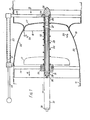
- the damper valve comprises a casing 10 in an air duct indicated at 11.
- the casing extends from its inflow end 12 where a valve seating 13 is provided, to a spider 14 at its outflow end 15.
- a valve member 16 formed from sheet metal to have a convex front face 17 and a concave rear face, is movable along a tubular spindle 18 which extends axially along the casing between the rear spider 14 and another spider 19 at the inflow end 12.
- the valve member 16 formed from sheet metal to have a convex front face 17 and a concave rear face, is movable along a tubular spindle 18 which extends axially along the casing between the rear spider 14 and another spider 19 at the inflow end 12.
- the valve member 16 is movable from a closed position at the valve seating 13, to a fully open position in engagement with hub 20 of the rear spider 14, by means of, in this embodiment, a hydraulic control system.
- This system comprises a piston 21 which is carried at the end of an actuating rod 22 for movement within a cylinder 23 which is mounted on the casing 10. Hydraulic fluid from cylinder 23 passes through a bore 24 in the upper limb of the front spider 19, to pass through boss 25 of the spider and enter the tubular spindle 18 which provides a cylinder 26.
- Piston 27 is movable within the cylinder 26 on one end of a rod 28 which is secured, at its other end, through a tapped disc 29 backed by a lock nut 30, to a tubular sleeve 31.
- the sleeve is telescopically mounted on the spindle 18 and carries the valve member 16 which is urged towards the closed position by compression spring 32.
- the piston rod may be threaded for manual or electric rotation to produce displacement, or may be pneumatically actuated.
- the seating 13 curved to approximately the same radius as the peripheral part of the valve member 16, as this has been found to minimise noise and drag.
- valve casing 10 has an inner face 33 which is so shaped, in relation to the characteristics of the valve member 16, that the degree of linear movement of the valve member is directly proportional to the effective degree of valve opening for any given pressure drop through the valve.
- the distance travelled by the valve member 16 in moving from the open position to the fully closed position is 12 cm.
- the air flow through the fully open valve is 60 m 3 per minute at a given pressure drop across the valve, .
- the air flow through the annular gap between the periphery of the valve member and the casing 33 will be 20 m 3 per minute when the valve has moved 8 cm. from the open position at the same pressure drop.
- a linear response of the valve alone may not however, be desirable, as discussed below.
- the shape of the inner face 33 of the valve casing 10 could be determined experimentally, starting from a malleable casing of frustoconical form as indicated by broken lines 36 and forming the casing as required at each one of a substantial number of positions of the valve members 16, by trial and error, following testing of the pressure drop across the valve. Starting with a conical valve in its fully open position, the pressure drop across the valve for a given volumetric flow of air can be determined, and the ideal pressure drop that would occur at each of the positions of the valve member 16 assuming the same volumetric flow of air can be calculated for a valve having the desired characteristics. Adjustment of the contour of the wall surface 33 could then be made with a view to obtaining in practice the desired pressure drop.
- such experimental formation of the valve casing 10 would be impractical and probably imprecise in view of the range of diameters and air velocities or air pressures which must be considered.
- the desired form of the valve casing can be determined by mathematical correction of an initial form of valve.
- the cone angle of an initially shaped frustoconical casing as indicated by the broken lines 36 should be less than 30 0 , and preferably in the region of 8°.
- the diameter of the inflow end of the frustoconical casing should be suited to the velocity of air flow to be encountered, and although as shown in the drawing the narrow end of the casing is of reduced diameter in relation to the ducting 11 within which the valve is to be used, for high velocities the narrow end of the frustum of the cone could correspond directly to the diameter of the ducting 11.
- valve casing must necessarily widen outwardly to a diameter greater than that of the ducting, and must be reduced again in diameter at a point sufficiently far beyond the outlet of the valve casing to avoid problems due to turbulence in the valve exit.
- the cross-sectional area of the wider end of the frustoconical casing should be approximately twice that at its inner end.
- valve member 17 should be flat or slightly curved, and that the outer skirt of the valve member should be radiused at a smaller radius of curvature as shown, the axial length of the valve member 16 being in the region of 1/4 of the distance of axial regulating movement of the valve member.
- This formation of the valve member is highly effective in deadening noise, such as fan noise, which travels axially along the duct.
- an annular spoiler indicated at 35 may be carried by the valve member 17, spaced from its rear face to reduce turbulence and thus also reduce noise even further. Further reduction of noise levels could be achieved by providing a sleeve of sound deadening material to surround both ends of the duct 11 for a length equal to 3 or 4 times the diameter of the duct.
- the reduction in cross-sectional area in relation to the duct at the entrance to the valve casing produces a drag coefficient which is constant, and which may be reduced by a minimum by the provision of well rounded corners to the entry to the valve casing and of streamlined spiders for support of the spindle of the valve member.
- a further area reduction involves a contraction loss, which is dependent of the formation of the valve member 17 and in particular the outer radiused skirt thereof.
- the drag coefficient of the entrance to the valve member is a variable function of the position of the valve member, and will hereinafter be designated.
- the drag coefficient is also a variable function of the position of the valve member and will hereinafter be designated u.
- the diverging area containing the valve member and the spindle hereinafter referred to as the diffuser section, produces a drag coefficient which varies slightly according to the position of the valve member. This drag coefficient is hereinafter referred to as d.
- the drag coefficient at this point may be reduced by streamlining of the spider and support for the spindle of the valve member.
- the drag coefficient is constant and will be designated us.
- the calculation of the correction required to compensate for the variable drag coefficient of the valve can be calculated in terms of the pressure drop required across the valve for a constant volume of air flow through the valve at each control position of the valve member.
- the drag coefficient at the outlet from the valve member may be expressed as where
- the corresponding area of the exit from the valve member and thus radial dimension ru of the valve casing at the exit from the valve member in corresponding positions of the latter can be calculated in relation to the desired pressure drop from the above formula (VI), using a successive approximation method.
- valve casing had a circular cross-section with maximum internal diameter 156 mm
- a valve member had an external diameter of 108 m and a regulating distance of movement of 90 mm with an axial dimension of 22.5 mm and an outer skirt of radius 22.5 mm
- the radial dimension ru of the valve casing at each axial position L of the exit part of the valve casing was as follows:
- the above description of the method of determining the shape of the valve casing has referred, for simplicity,to the production of a valve having a desired linear relationship between the movement of the valve member and the change in volume of air flow at a predetermined pressure drop, this is not necessarily desirable, as mentioned above.
- the system will, as known, comprise a ⁇ value; where Pv is the pressure drop across the valve and Ps is the pressure drop across the combination of the duct and valve.
- the ⁇ value may be as low as 0.09, which considerably modifies the response of a valve which, alone, has a linear response.
- Figure 4 illustrates curves of the change in volume flow of air V in relation to the control movement of the valve member L in the case of a valve as described above, wherein curve A illustrates the response of the valve alone for a given pressure drop across the valve, and curves A', A", A"' illustrate response curves in relation to the same pressure drop across the system when the valve is incorporated in systems having various values.
- the valve described above In order to compensate for a predetermined P value, therefore,the valve described above must be recompensated by carrying out the above steps of successive approximation in relation to a different set of wanted pressure values corrected to take account of the ⁇ value. This may be carried out either during the initial stages of calculation, or starting from the figures derived in the case of a valve already compensated to a linear response.
- the response of a valve as described is matched to the ⁇ value of a given system
- the response of the system may be corrected to be linear
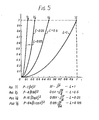
- Figure 5 shows operation curves for such a system, wherein P is the pressure drop across the system, V is the volume of air flow through the valve and curves L, L', L", etc. indicate given setting positions of the valve member.
- Such operation curves may be utilised to derive air flow measurements in such a system in use, at corresponding setting positions of the valve, simply by taking.pressure measurements in selected setting positions and reading the corresponding air flow value from the graph.
- the functions of the respective curves may be stored in a suitable automatic control system for the ventilation system.
- valves according to the invention have the obvious advantage of simplicity in operation and control, and this is particularly attractive to conditions of remote control and to the operation of valves in balance, for example, in ventilating systems where inlet and exhaust valves are coupled to operate in unison, or where hot and cold air flows are mixed in inverse proportions.
- Another application of the valve is in controlling air flow pressures and maintaining such pressures at constant values.
- valves described above A further attraction of the valve described above is that the flow is always around the periphery of the valve member 16 and thus remote from the centre of the air duct where the flow speed tends to be greatest. As a result, the noise level in operation is minimised, as opposed to, for example, iris valves where high-speed central gas flow may produce high noise levels, particularly in the lower range of valve openings.
Landscapes
- Engineering & Computer Science (AREA)
- General Engineering & Computer Science (AREA)
- Physics & Mathematics (AREA)
- Fluid Mechanics (AREA)
- Mechanical Engineering (AREA)
- Chemical & Material Sciences (AREA)
- Combustion & Propulsion (AREA)
- Lift Valve (AREA)
Applications Claiming Priority (2)
| Application Number | Priority Date | Filing Date | Title |
|---|---|---|---|
| GB2452378 | 1978-05-30 | ||
| GB2452378 | 1978-05-30 |
Publications (2)
| Publication Number | Publication Date |
|---|---|
| EP0007165A1 true EP0007165A1 (de) | 1980-01-23 |
| EP0007165B1 EP0007165B1 (de) | 1983-03-02 |
Family
ID=10213002
Family Applications (1)
| Application Number | Title | Priority Date | Filing Date |
|---|---|---|---|
| EP19790300970 Expired EP0007165B1 (de) | 1978-05-30 | 1979-05-29 | Durchflussregelventil für Luft und Verfahren zu seiner Herstellung |
Country Status (3)
| Country | Link |
|---|---|
| US (1) | US4305418A (de) |
| EP (1) | EP0007165B1 (de) |
| DE (1) | DE2964946D1 (de) |
Cited By (2)
| Publication number | Priority date | Publication date | Assignee | Title |
|---|---|---|---|---|
| WO1984004798A1 (en) * | 1983-05-26 | 1984-12-06 | Bubb Anthony John Allen | Throttled fluid mixing device |
| WO1984004805A1 (en) * | 1983-05-26 | 1984-12-06 | Bubb Anthony John Allen | Improvements in fluid flow control valves |
Families Citing this family (10)
| Publication number | Priority date | Publication date | Assignee | Title |
|---|---|---|---|---|
| US4749001A (en) * | 1987-10-19 | 1988-06-07 | American Standard Inc. | Normally closed pneumatic air valve |
| US4749000A (en) * | 1987-10-19 | 1988-06-07 | American Standard Inc. | Normally open pneumatic air valve |
| US4775133A (en) * | 1987-10-19 | 1988-10-04 | American Standard Inc. | Electric air valve |
| US4884590A (en) * | 1988-12-05 | 1989-12-05 | American Standard Inc. | Electric motor driven air valve |
| US5674125A (en) * | 1995-01-24 | 1997-10-07 | American Standard Inc. | Fresh air flow modulation device |
| GB9716618D0 (en) * | 1997-08-07 | 1997-10-15 | Emhart Glass Mach Invest | Control valve |
| US6631716B1 (en) * | 1998-07-17 | 2003-10-14 | The Board Of Trustees Of The Leland Stanford Junior University | Dynamic respiratory control |
| DE10207658B4 (de) * | 2002-02-22 | 2008-09-04 | Meta Motoren- Und Energie-Technik Gmbh | Verfahren zum Verkürzen der Öffnungs- und Schließflanke eines Ventils, sowie Ventil |
| US8621707B2 (en) * | 2008-03-20 | 2014-01-07 | Ryco Canada, Inc. | Intake control for blower in vehicle wash system |
| CN108548276B (zh) * | 2018-03-30 | 2020-07-07 | 青岛海尔空调电子有限公司 | 调节空调出风量的方法、装置及计算机可读存储介质 |
Citations (4)
| Publication number | Priority date | Publication date | Assignee | Title |
|---|---|---|---|---|
| DE503543C (de) * | 1928-01-27 | 1930-07-24 | E H Hugo Junkers Dr Ing | Selbsttaetiges Durchgangsventil |
| AT247090B (de) * | 1961-06-14 | 1966-05-25 | Zimmer Verfahrenstechnik | Reduzierventil für strömende Medien |
| AT269583B (de) * | 1965-02-25 | 1969-03-25 | Rox Lufttechnische Geraetebau | Durchflußregler für gasförmige Medien |
| DE2164029A1 (de) * | 1971-01-18 | 1972-07-27 | Rickenbach H | Schnellschlußventil |
Family Cites Families (14)
| Publication number | Priority date | Publication date | Assignee | Title |
|---|---|---|---|---|
| US856981A (en) * | 1906-08-17 | 1907-06-11 | Burnham Williams & Co | Means for hydraulically operating valves and cocks. |
| GB360727A (en) | 1930-10-13 | 1931-11-12 | Forenede Jernsta Berier Akties | Improvements in or relating to outlet nozzles for the supply of ventilation air |
| GB418812A (en) | 1934-03-20 | 1934-10-31 | William Heywood Mottershall | Improvements in and relating to ventilators |
| US2055347A (en) * | 1934-08-17 | 1936-09-22 | Arthur J Hackman | Remote control operating mechanism |
| US2357527A (en) * | 1943-01-14 | 1944-09-05 | Wright Aeronautical Corp | Impeller throttle |
| GB1025481A (en) | 1962-05-15 | 1966-04-14 | Burgess Products Co Ltd | Improvements in or relating to ventilating apparatus |
| FR1341583A (fr) * | 1962-09-12 | 1963-11-02 | Metallurg A Durenne Et Du Val | Dispositif à soupape d'arrêt automatique pour fluide |
| GB1099721A (en) | 1965-02-19 | 1968-01-17 | Bahco Ab | Apparatus for regulating ventilation |
| CH497900A (de) | 1966-05-23 | 1970-10-31 | Rickenbach Hugo | Ventil für Schutzbauten |
| US3415486A (en) * | 1966-05-25 | 1968-12-10 | Anne S De Frees | Spring biased tank outlet valve |
| US3403852A (en) * | 1966-07-28 | 1968-10-01 | Gorchev Dimiter | Dual duct fluid supply system |
| DE1817272B2 (de) * | 1968-12-27 | 1971-04-08 | Ventilgehaeuse fuer unterschiedliche anschlussarten | |
| AU3066771A (en) | 1970-07-10 | 1973-01-04 | Dimiter Goschen | Diffuser valve |
| US4082114A (en) * | 1977-01-28 | 1978-04-04 | The Trane Company | Valve assembly for use in an air distribution system |
-
1979
- 1979-05-29 EP EP19790300970 patent/EP0007165B1/de not_active Expired
- 1979-05-29 DE DE7979300970T patent/DE2964946D1/de not_active Expired
- 1979-05-29 US US06/043,025 patent/US4305418A/en not_active Expired - Lifetime
Patent Citations (4)
| Publication number | Priority date | Publication date | Assignee | Title |
|---|---|---|---|---|
| DE503543C (de) * | 1928-01-27 | 1930-07-24 | E H Hugo Junkers Dr Ing | Selbsttaetiges Durchgangsventil |
| AT247090B (de) * | 1961-06-14 | 1966-05-25 | Zimmer Verfahrenstechnik | Reduzierventil für strömende Medien |
| AT269583B (de) * | 1965-02-25 | 1969-03-25 | Rox Lufttechnische Geraetebau | Durchflußregler für gasförmige Medien |
| DE2164029A1 (de) * | 1971-01-18 | 1972-07-27 | Rickenbach H | Schnellschlußventil |
Cited By (5)
| Publication number | Priority date | Publication date | Assignee | Title |
|---|---|---|---|---|
| WO1984004798A1 (en) * | 1983-05-26 | 1984-12-06 | Bubb Anthony John Allen | Throttled fluid mixing device |
| WO1984004805A1 (en) * | 1983-05-26 | 1984-12-06 | Bubb Anthony John Allen | Improvements in fluid flow control valves |
| EP0127991A1 (de) * | 1983-05-26 | 1984-12-12 | Spiro Machines S.A. | Gedrosselte Mischvorrichtung für Fluide |
| EP0128690A1 (de) * | 1983-05-26 | 1984-12-19 | Spiro Machines S.A. | Durchflussregelventile für Fluide |
| US4609506A (en) * | 1983-05-26 | 1986-09-02 | Spiro Investment A.G. | Throttled fluid mixing device |
Also Published As
| Publication number | Publication date |
|---|---|
| US4305418A (en) | 1981-12-15 |
| DE2964946D1 (en) | 1983-04-07 |
| EP0007165B1 (de) | 1983-03-02 |
Similar Documents
| Publication | Publication Date | Title |
|---|---|---|
| EP0007165B1 (de) | Durchflussregelventil für Luft und Verfahren zu seiner Herstellung | |
| US4091835A (en) | Autokinetic sampling nozzle | |
| US2668416A (en) | Fuel control apparatus for turbojet engines | |
| US3981326A (en) | Induction mixing nozzle | |
| US4092998A (en) | Automatic pressure regulator | |
| US3068891A (en) | Flow regulator for air control | |
| US20020162589A1 (en) | Fluid control device with reduced sound generation | |
| US4306585A (en) | Constant flow valve | |
| US3523559A (en) | Fluid flow control device | |
| CN109059217A (zh) | 一种基于运行曲线的变风量空调系统总风量控制方法 | |
| US3865021A (en) | Air injecting apparatus for air conditioners or the like | |
| JPS6176800A (ja) | 蒸気エゼクタ− | |
| US2905543A (en) | Proportional mixer | |
| JP2730749B2 (ja) | 流体装置 | |
| US3926102A (en) | Air injecting apparatus for air conditioners or the like | |
| EP0128690B1 (de) | Durchflussregelventile für Fluide | |
| GB1603072A (en) | Valve for air flow control | |
| EP1334316B1 (de) | Ventil für variable strömungen, feuerklappe und kombinierte feuerklappe und ventil für variable strömungen | |
| GB2125944A (en) | Regulating valve | |
| US4181469A (en) | Apparatus for adding emulsifier to a fluid | |
| US2498194A (en) | Flow control valve | |
| JPH0579867A (ja) | ウオルトマン形積算計 | |
| US5373987A (en) | Variable volume air valve | |
| US2969009A (en) | Centrifugal take-off and control nozzle | |
| US2713350A (en) | Damper |
Legal Events
| Date | Code | Title | Description |
|---|---|---|---|
| PUAI | Public reference made under article 153(3) epc to a published international application that has entered the european phase |
Free format text: ORIGINAL CODE: 0009012 |
|
| AK | Designated contracting states |
Designated state(s): BE CH DE FR GB NL SE |
|
| 17P | Request for examination filed | ||
| GRAA | (expected) grant |
Free format text: ORIGINAL CODE: 0009210 |
|
| AK | Designated contracting states |
Designated state(s): BE CH DE FR GB NL SE |
|
| ET | Fr: translation filed | ||
| REF | Corresponds to: |
Ref document number: 2964946 Country of ref document: DE Date of ref document: 19830407 |
|
| REG | Reference to a national code |
Ref country code: CH Ref legal event code: PFA Free format text: SPIRO MACHINES S.A. |
|
| PGFP | Annual fee paid to national office [announced via postgrant information from national office to epo] |
Ref country code: GB Payment date: 19900514 Year of fee payment: 12 |
|
| PGFP | Annual fee paid to national office [announced via postgrant information from national office to epo] |
Ref country code: SE Payment date: 19900521 Year of fee payment: 12 |
|
| PGFP | Annual fee paid to national office [announced via postgrant information from national office to epo] |
Ref country code: CH Payment date: 19900529 Year of fee payment: 12 |
|
| PGFP | Annual fee paid to national office [announced via postgrant information from national office to epo] |
Ref country code: NL Payment date: 19900531 Year of fee payment: 12 |
|
| PGFP | Annual fee paid to national office [announced via postgrant information from national office to epo] |
Ref country code: BE Payment date: 19910423 Year of fee payment: 13 |
|
| PGFP | Annual fee paid to national office [announced via postgrant information from national office to epo] |
Ref country code: FR Payment date: 19910430 Year of fee payment: 13 |
|
| PGFP | Annual fee paid to national office [announced via postgrant information from national office to epo] |
Ref country code: DE Payment date: 19910502 Year of fee payment: 13 |
|
| PG25 | Lapsed in a contracting state [announced via postgrant information from national office to epo] |
Ref country code: DE Effective date: 19910528 |
|
| PG25 | Lapsed in a contracting state [announced via postgrant information from national office to epo] |
Ref country code: GB Effective date: 19910529 |
|
| PG25 | Lapsed in a contracting state [announced via postgrant information from national office to epo] |
Ref country code: SE Effective date: 19910530 |
|
| PG25 | Lapsed in a contracting state [announced via postgrant information from national office to epo] |
Ref country code: CH Effective date: 19910531 |
|
| PG25 | Lapsed in a contracting state [announced via postgrant information from national office to epo] |
Ref country code: NL Effective date: 19911201 |
|
| NLV4 | Nl: lapsed or anulled due to non-payment of the annual fee | ||
| GBPC | Gb: european patent ceased through non-payment of renewal fee | ||
| REG | Reference to a national code |
Ref country code: CH Ref legal event code: PL |
|
| PG25 | Lapsed in a contracting state [announced via postgrant information from national office to epo] |
Ref country code: BE Effective date: 19920531 |
|
| BERE | Be: lapsed |
Owner name: SPIRO INVESTMENT S.A. Effective date: 19920531 |
|
| PG25 | Lapsed in a contracting state [announced via postgrant information from national office to epo] |
Ref country code: FR Effective date: 19930129 |
|
| REG | Reference to a national code |
Ref country code: FR Ref legal event code: ST |
|
| EUG | Se: european patent has lapsed |
Ref document number: 79300970.5 Effective date: 19911209 |
|
| PLBE | No opposition filed within time limit |
Free format text: ORIGINAL CODE: 0009261 |
|
| STAA | Information on the status of an ep patent application or granted ep patent |
Free format text: STATUS: NO OPPOSITION FILED WITHIN TIME LIMIT |