EP0007564A1 - Auflageplatte für ein fotoleitfähiges bandförmiges Aufzeichnungsmaterial - Google Patents
Auflageplatte für ein fotoleitfähiges bandförmiges Aufzeichnungsmaterial Download PDFInfo
- Publication number
- EP0007564A1 EP0007564A1 EP79102508A EP79102508A EP0007564A1 EP 0007564 A1 EP0007564 A1 EP 0007564A1 EP 79102508 A EP79102508 A EP 79102508A EP 79102508 A EP79102508 A EP 79102508A EP 0007564 A1 EP0007564 A1 EP 0007564A1
- Authority
- EP
- European Patent Office
- Prior art keywords
- support plate
- recording material
- grid
- platen
- bushing
- Prior art date
- Legal status (The legal status is an assumption and is not a legal conclusion. Google has not performed a legal analysis and makes no representation as to the accuracy of the status listed.)
- Granted
Links
- 239000000463 material Substances 0.000 title claims abstract description 25
- 239000002184 metal Substances 0.000 claims abstract description 23
- 230000000284 resting effect Effects 0.000 claims description 2
- 238000000034 method Methods 0.000 description 5
- 238000011109 contamination Methods 0.000 description 3
- 238000009825 accumulation Methods 0.000 description 1
- 239000000919 ceramic Substances 0.000 description 1
- 229910010293 ceramic material Inorganic materials 0.000 description 1
- 238000004140 cleaning Methods 0.000 description 1
- 230000006378 damage Effects 0.000 description 1
- 239000000428 dust Substances 0.000 description 1
- 230000007613 environmental effect Effects 0.000 description 1
- 230000007274 generation of a signal involved in cell-cell signaling Effects 0.000 description 1
- 238000003384 imaging method Methods 0.000 description 1
- 230000007774 longterm Effects 0.000 description 1
- 238000004519 manufacturing process Methods 0.000 description 1
- 230000002787 reinforcement Effects 0.000 description 1
- 230000001960 triggered effect Effects 0.000 description 1
Images
Classifications
-
- G—PHYSICS
- G03—PHOTOGRAPHY; CINEMATOGRAPHY; ANALOGOUS TECHNIQUES USING WAVES OTHER THAN OPTICAL WAVES; ELECTROGRAPHY; HOLOGRAPHY
- G03G—ELECTROGRAPHY; ELECTROPHOTOGRAPHY; MAGNETOGRAPHY
- G03G15/00—Apparatus for electrographic processes using a charge pattern
- G03G15/75—Details relating to xerographic drum, band or plate, e.g. replacing, testing
- G03G15/754—Details relating to xerographic drum, band or plate, e.g. replacing, testing relating to band, e.g. tensioning
-
- G—PHYSICS
- G03—PHOTOGRAPHY; CINEMATOGRAPHY; ANALOGOUS TECHNIQUES USING WAVES OTHER THAN OPTICAL WAVES; ELECTROGRAPHY; HOLOGRAPHY
- G03G—ELECTROGRAPHY; ELECTROPHOTOGRAPHY; MAGNETOGRAPHY
- G03G21/00—Arrangements not provided for by groups G03G13/00 - G03G19/00, e.g. cleaning, elimination of residual charge
- G03G21/14—Electronic sequencing control
- G03G21/145—Electronic sequencing control wherein control pulses are generated by the mechanical movement of parts of the machine, e.g. the photoconductor
Definitions
- the invention relates to a support plate for a photoconductive tape-shaped recording material which runs in an endless loop and is provided with perforations near and parallel to one of the two longitudinal edges, a metal brush resting against the recording material in the region of the perforated longitudinal edge.
- photoconductive tape-shaped recording materials such as organic photoconductor tapes in the form of endless tapes.
- the timing and the synchronization of the individual process steps to one another are carried out by means of electrical contactors.
- electrical contactors For this purpose, from the annual meeting of the IEEE Industry Applications Society, Oct. In 1977, lectures on the use of an organic photoconductor with a number of holes along its front edge became known. These are standard perforations, as are commonly used with 35 mm films. These perforations form a means of generating time signals related to film motion.
- This known organic photoconductor consists of the photoconductive layer, the underlying electrically conductive layer and a carrier layer. In addition to the usual length perforations, there are six double length perforations.
- These six double-length perforations deliver signals to the microprocessor system the electrophotographic copying machine in which the photoconductor belt is used, these signals, among other things, triggering the flash exposures of six imaging elements along the length of the photoconductor belt.
- the photoconductor tape backing is electrically connected by a wire brush in contact with a strip that is applied along the edge of the photoconductor tape.
- the time signals are generated by means of a double sensor. This is actuated by a hammer, which lies against the photoconductor tape along the perforations under slight pressure. If a perforation passes under the hammer, it strikes the support plate on which piezoelectric strips are attached. The strips of piezoelectric ceramic material are poled in opposite directions to one another in order to generate a correspondingly large electrical signal each time the hammer is actuated and are part of the hammer arrangement. The hammer exerts very little force on the photoconductor belt so that there is no destruction. The signal generation is stable over a very large number of operations of the hammer and is not susceptible to contamination and environmental influences. However, it can be seen that the use of Piezoelectric ceramic strips require a subsequent amplifier or a high-resistance and therefore fault-prone line, which also increases the manufacturing costs.
- a tape-shaped recording material which has markings for controlling the advance movement, which can be electrically conductive markings, perforations or the like, which are applied before the recording material is installed.
- a photoconductive tape-shaped recording material with holes or perforations in which contact brushes made of metal grind at the level of the holes on the photoconductor surface, the photoconductor moving along the surface of an earthed metal plate, the contact is made by touching the metallic Contact brush with the metal plate at the locations of the perforations.
- the contact is low-resistance and can be used directly electrically without the need for a high-resistance line or reinforcement.
- This can result in long-term copying problems due to toner contamination, which is caused by the fact that toner gets into the holes and is transported with the photoconductor belt and settles on the metal plate and on the contact brushes, which leads to an interruption of the electrical contact comes between the contact brushes and the metal plate .
- the object of the invention is to improve a platen of the type described above for a photoconductive tape-shaped recording material so that there are no interruptions in the electrical contact between the platen and the metal brush in the area of the perforations of the recording material due to toner contamination of the recording material and deposits of toner in the perforations can come.
- each bushing has at least one gradation and the grating lies on this gradation.
- the top of the grid expediently ends flush with the support surface of the support plate, which ensures that the photoconductor belt can be moved smoothly over the support plate.
- the grid is preferably a wire mesh, the mesh size of which is up to 2 mm. In particular, the mesh size of the grid can be approximately 1 mm.
- the embodiment of the invention is such that the longitudinal dimension of a perforation is smaller than the longitudinal dimension of the gradation and larger than the diameter of the bushing.
- the platen is grounded and connected to the metal brush via a relay. As soon as the contact between the metal brush and the platen is made, the relay is actuated to give a corresponding control impulse for the exact control of the advance of the photoconductor belt.
- the advantage is achieved that a good electrical contact is always made between the metal brush and the platen, since the resulting toner dust is automatically discharged through the wire mesh without causing sticking of the contact surface of the platen.
- the metal brush brushes the contact point again.
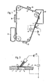
- a photoconductive tape-shaped recording material 9 is schematically shown, which is assembled into an endless tape and is guided over rollers.
- Various process stations of the electrophotographic copier are arranged along the recording material, such as, for example, a charging corona 10, a development station 11, a transfer corona 12, a cleaning station 13 and an erasing lamp 14.
- the recording material 9 runs over support plates 1, one of which is on the ground and over one Relay 6 and a voltage source 15 is connected to a metal brush 7, which rests with its metal bristles on the front of the recording material.
- the support plate 1 which has a gradation 4. It there may also be several levels, although this is not shown.
- the bushing 2 is covered by an electrically conductive grid 3, which rests on the step 4.
- This grid 3 is preferably a wire mesh grid which has a mesh size of up to 2 mm. In particular, a mesh with a mesh size of 1 mm is used.
- Conventional wire mesh grids can be used as grids, which are available at particularly low cost.
- the top of the grating 3 is flush with the support surface 5 of the support plate 1, thereby ensuring that the recording tape 9 moves smoothly over the support plate 1.
- Toner material which is deposited on the platen 1 through the perforations of the recording tape 9, passes through the grating 3 and the passage 2, for example a hole, so that no toner accumulation occurs on the platen 1, which gives rise to a break in contact between the metal brush 7 and the Platen 1 could be.
- the individual perforation 8 is designed such that its longitudinal dimension is smaller than the longitudinal dimension of the step 4 and larger than the diameter of the bushing 2.
- each of the metal Brush 7 is connected via a relay 6 to the grounded platen 1. It is not necessary that all metal brushes 7 are assigned to the same support plate 1, rather the metal brushes 7 can be divided onto the individual support plates 1 along the path of the recording tape 9.
Landscapes
- Physics & Mathematics (AREA)
- General Physics & Mathematics (AREA)
- Printers Or Recording Devices Using Electromagnetic And Radiation Means (AREA)
- Cleaning In Electrography (AREA)
- Photoreceptors In Electrophotography (AREA)
- Discharging, Photosensitive Material Shape In Electrophotography (AREA)
Abstract
Description
- Die Erfindung betrifft eine Auflageplatte für ein fotoleitfähiges bandförmiges Aufzeichnungsmaterial, das in einer endlosen Schleife umläuft und nahe und parallel zu einer der beiden Längskanten mit Perforationen versehen ist, wobei eine Metallbürste gegen das Aufzeichnungsmaterial im Bereich der perforierten Längskante aniiegt.
- In elektrofotografischen Kopiergeräten werden fotoleitfähige bandförmige Aufzeichnungsmaterialien, wie beispielsweise organische Fotoleiterbänder in Form von Endlosbändern benutzt. Der zeitliche Ablauf sowie die Synchronisation der einzelnen Verfahrensschritte zueinander erfolgen mittels elektrischer Kontaktgeber. Hierzu ist aus den auf dem Jahrestreffen der IEEE Industry Applications Society, Oct. 1977, gehaltenen Referaten die Anwendung eines organischen Fotoleiters bekannt geworden, der eine Anzahl von Löchern längs seiner Vorderkante besitzt. Hierbei handelt es sich um Standardperforationen, wie sie üblicherweise bei 35 mm-Filmen verwendet werden. Diese Perforationen bilden ein Mittel zur Erzeugung von Zeitsignalen, die auf die Filmbewegung bezogen sind. Dieser bekannte organische Fotoleiter besteht aus der fotoleitenden Schicht, der darunter liegenden elektrisch leitenden Schicht und einer Trägerschicht. Neben den Perforationen der üblichen Länge gibt es noch sechs Perforationen doppelter Länge. Diese sechs doppeltlangen Perforationen liefern Signale zu dem Mikroprozessor-System der elektrofotografischen Kopiermaschine, in der das Fotoleiterband verwendet wird, wobei diese Signale u.a. die Blitzbelichtungen von sechs Abbildungselementen längs der Fotoleiterbandlänge auslösen. Zwischen je zwei doppeltlangen Perforationen sind fünfzig Standardperforationen vorhanden, und die von diesen Perforationen ausgelösten Signale werden dazu verwandt, den Zeitablauf der übrigen Prozesschritte zu steuern.
- Die elektrische Verbindung der Trägerschicht des Fotoleiterbandes erfolgt durch eine Drahtbürste, die sich in Kontakt mit einem Streifen befindet, der längs der Kante'des Fotoleiterbandes aufgebracht ist.
- Die Zeitsignale werden mittels eines Doppelfühlers erzeugt. Dieser wird durch einen Hammer betätigt, der gegen das Fotoleiterband längs der Perforationen unter leichtem Druck anliegt. Wenn eine Perforation unter dem Hammer hindurchläuft, schlägt dieser auf die Auflageplatte auf, auf der piezoelektrische Streifen angebracht sind. Die Streifen aus piezoelektrischem Keramikmaterial sind zueinander in entgegengesetzte Richtungen gepolt, um ein entsprechend großes elektrisches Signal bei jeder Betätigung des Hammers zu erzeugen und sind Bestandteil der Hammeranordnung. Der Hammer übt sehr geringe Kräfte auf das Fotoleiterband aus, so daß es zu keinen Zerstörungen kommt. Die Signalerzeugung ist über eine sehr große Anzahl von Betätigungen des Hammers stabil und gegenüber Verschmutzung und Umgebungseinflüssen nicht anfällig. Es ist aber ersichtlich, daß die Verwendung von piezoelektrischen Keramikstreifen einen nachfolgenden Verstärker bzw. eine hochohmige und damit störanfällige Leitung erforderlich macht, wodurch die Herstellungskosten im übrigen auch ansteigen.
- Aus der DE-AS 22 20 909 ist ein Verfahren zum abschnittweisen Betrieb eines fotoleitfähigen bandförmigen Aufzeichnungsmaterials in einer elektrofotografischen Kopiermaschine bekannt, wobei der Durchlauf bzw. die Bewegung des Aufzeichnungsmaterials mittels in oder an dem Aufzeichnungsmaterial gebildeten Markierungen gesteuert wird, die von einer Leseeinrichtung festgestellt und zu die Vorbewegung steuernden Informationen umgewandelt werden. Hierbei werden die Markierungen erst beim Durchlauf des bandförmigen Aufzeichnungsmaterials, für jede gewünschte Formatgröße, genau an der richtigen Stelle in der Kopiermaschine selbst gebildet.
- Aus der DE-AS 12 63 509 ist ein bandförmiges Aufzeichnungsmaterial bekannt, das zur Steuerung der Vorbewegung Markierungen aufweist, die elektrisch leitende Harkierungen, Perforationen oder dgl. sein können, die vor dem Einbau des Aufzeichnungsmaterials angebracht werden.
- Wird ein fotoleitfähiges bandförmiges Aufzeichnungsmaterial mit Löchern bzw. Perforationen verwendet, bei dem auf der Fotoleiteroberfläche Kontaktbürsten aus Metall in Höhe der Löcher schleifen, wobei sich der Fotoleiter längs der Oberfläche einer geerdeten Metallplatte bewegt, so erfolgt der Kontakt durch Berühren der metallischen Kontaktbürste mit der Metallplatte an den Stellen der Perforationen. Der Kontakt geschieht niederohmig und kann direkt elektrisch weiterverwendet werden, ohne daß eine hochohmige Leitung bzw. eine Verstärkung erforderlich sind. Hierbei kann es jedoch im länger dauernden Kopierbetrieb zu Störungen durch Tonerverschmutzungen kommen, die dadurch verursacht werden, daß Toner in die Löcher gelangt und mit dem Fotoleiterband transportiert wird und sich auf der Metallplatte und an den Kontaktbürsten absetzt, wodurch es zu einer Unterbrechung des elektrischen Kontaktes zwischen den Kontaktbürsten und der Metallplatte kommt..
- Aufgabe der Erfindung ist es, eine Auflageplatte der eingangs beschriebenen Art für ein fotoleitfähiges bandförmiges Aufzeichnungsmaterial so zu verbessern, daß es nicht zu Unterbrechungen des elektrischen Kontaktes zwischen der Auflageplatte und der Metallbürste im Bereich der Perforationen des Aufzeichnungsmaterials durch Tonerverschmutzungen des Aufzeichnungsmaterials und Absetzungen von Toner in den Perforationen kommen kann.
- Diese Aufgabe wird gemäß der Erfindung dadurch gelöst, daß in der Auflageplatte zumindest eine Durchführung vorhanden ist, die durch ein elektrisch leitendes Gitter abgedeckt ist.
- Es ist selbstverständlich, daß nicht nur eine Durchführung sondern auch mehrere Durchführungen mit einer entsprechenden Anzahl von Metallbürsten im Bereich jeder Durchführung vorgesehen werden können.
- In Ausgestaltung der Erfindung weist jede Durchführung zumindest eine Abstufung auf und es liegt das Gitter auf dieser Abstufung auf. Die Oberseite des Gitters schließt zweckmäßigerweise mit der Auflagefläche der Auflageplatte eben ausgerichtet ab, wodurch sichergestellt ist, daß das Fotoleiterband glatt über die Auflageplatte bewegt werden kann. Das Gitter ist bevorzugt ein Maschendrahtgitter, dessen Maschenweite bis zu 2 mm beträgt. Insbesondere kann die Maschenweite des Gitters etwa 1 mm sein.
- Die Ausbildung der Erfindung geschieht derart, daß die Längsabmessung einer Perforation kleiner als die Längsabmessung der Abstufung und größer als der Durchmesser der Durchführung ist. Die Auflageplatte ist geerdet und über ein Relais mit der Metallbürste verbunden. Sobald der Kontakt zwischen der Metallbürste und der-Auflageplatte hergestellt ist, wird das Relais betätigt, um einen entsprechenden Steuerimpuls für die exakte Steuerung der Vorbewegung des Fotoleiterbandes abzugeben.
- Mit der Erfindung wird der Vorteil erzielt, daß jederzeit ein guter elektrischer Kontakt zwischen der Metallbürste und der Auflageplatte hergestellt wird, da der anfallende Tonerstaub durch das Maschendrahtgitter selbsttätig abgeführt wird, ohne daß es zu Verklebungen der Kontaktfläche der Auflageplatte kommen kann. Die Metallbürste bürstet jeweils die Kontaktstelle wieder frei.
- Im folgenden wird eine Ausführungsform der Erfindung anhand der Zeichnungen erläutert, die in
- Fig. 1 eine schematische Ansicht der Bahn des fotoleitfähigen bandförmigen Aufzeichnungsmaterials und einzelner elektrofotografischer Verfahrensstationen, und in
- Fig. 2 eine vergrößerte Teilansicht einer Auflageplatte mit darüber geführtem fotoleitfähigem Aufzeichnungsmaterial
- In Fig. 1 ist schematisch ein fotoleitfähiges bandförmiges Aufzeichnungsmaterial 9 dargestellt, das zu einem endlosen Band zusammengefügt ist und über Rollen geführt wird. Längs dem Aufzeichnungsmaterial sind verschiedene Verfahrensstationen des elektrofotografischen Kopiergeräts angeordnet, wie beispielsweise eine Aufladungskorona 10, eine Entwicklungsstation 11, eine Übertragungskorona 12, eine Reinigungsstation 13 und eine Löschlampe 14. Das Aufzeichnungsmaterial 9 läuft über Auflageplatten 1, von denen eine auf Masse liegt und über ein Relais 6 und eine Spannungsquelle 15 mit einer Metallbürste 7 verbunden ist, die mit ihren Metallborsten an der Vorderseite des Aufzeichnungsmaterials anliegt.
- Wie die vergrößerte Teilansicht nach Fig. 2 erkennen liißt, ist in der Auflageplatte 1 zumindest eine Durchführung 2 vorhanden, die eine Abstufung 4 aufweist. Es können auch mehrere Abstufungen vorhanden sein, obwohl dies nicht dargestellt ist. Die Durchführung 2 ist durch ein elektrisch leitendes Gitter 3 abgedeckt, das auf der Abstufung 4 aufliegt. Dieses Gitter 3 ist bevorzugt ein Maschendrahtgitter, das eine Maschenweite bis zu 2 mm besitzt. Insbesondere wird ein Maschengitter mit einer Maschenweite von 1 mm verwendet. Als Gitter können herkömmliche Maschendrahtgitter zum Einsatz kommen, die besonders preiswert erhältlich sind.
- Die Oberseite des Gitters 3 schließt eben ausgerichtet mit der Auflagefläche 5 der Auflageplatte 1 ab, wodurch sichergestellt ist, daß sich das Aufzeichnungsband 9 glatt über die Auflageplatte 1 hinweg bewegt. Tonernaterial, das durch die Perforationen des Aufzeichnungsbandes 9 auf der Auflageplatte 1 abgelagert wird, durchsetzt das Gitter 3 und die Durchführung 2, beispielsweise eine Bohrung, so daß keine Toneranhäufung auf der Auflageplatte 1 auftritt, die Anlaß zu einer Kontaktunterbrechung zwischen der Matallbürste 7 und der Auflageplatte 1 sein könnte.
- Die einzelne Perforation 8 ist so ausgebildet, daß ihre Längsabmessung kleiner als die Längsabmessung der Abstufung 4 und größer als der Durchmesser der Durchführung 2 ist..
- Es ist selbstverständlich, daß mehr als eine Metallbürste 7 mit zugehöriger Durchführung 2 in der Auflageplatte 1 vorhanden sein können, wobei jede der Metallbürsten 7 über jeweils ein Relais 6 mit der geerdeten Auflageplatte 1 verbunden ist. Dabei ist es nicht erforderlich, daß alle Metallbürsten 7 der gleichen Auflageplatte 1 zugeordnet sind, vielmehr kann eine Aufteilung der Metallbürsten 7 auf die einzelnen Auflageplatten 1 längs der Bahn des Aufzeichnungsbandes 9 erfolgen.
zeigen.
Claims (7)
Applications Claiming Priority (2)
| Application Number | Priority Date | Filing Date | Title |
|---|---|---|---|
| DE2832775 | 1978-07-26 | ||
| DE19782832775 DE2832775A1 (de) | 1978-07-26 | 1978-07-26 | Auflageplatte fuer ein fotoleitfaehiges bandfoermiges aufzeichnungsmaterial |
Publications (2)
| Publication Number | Publication Date |
|---|---|
| EP0007564A1 true EP0007564A1 (de) | 1980-02-06 |
| EP0007564B1 EP0007564B1 (de) | 1981-09-16 |
Family
ID=6045417
Family Applications (1)
| Application Number | Title | Priority Date | Filing Date |
|---|---|---|---|
| EP79102508A Expired EP0007564B1 (de) | 1978-07-26 | 1979-07-18 | Auflageplatte für ein fotoleitfähiges bandförmiges Aufzeichnungsmaterial |
Country Status (5)
| Country | Link |
|---|---|
| US (1) | US4273437A (de) |
| EP (1) | EP0007564B1 (de) |
| JP (1) | JPS5518699A (de) |
| CA (1) | CA1127704A (de) |
| DE (2) | DE2832775A1 (de) |
Families Citing this family (5)
| Publication number | Priority date | Publication date | Assignee | Title |
|---|---|---|---|---|
| US4402593A (en) * | 1981-12-31 | 1983-09-06 | Pittney Bowes Inc. | Grounding device for moving photoconductor web |
| DE3607472A1 (de) * | 1986-03-07 | 1987-09-10 | Hoechst Ag | Verfahren zum elektrostatischen aufladen von aufzeichnungsmaterialien sowie vorrichtung zur durchfuehrung des verfahrens |
| JPS63188820U (de) * | 1987-05-28 | 1988-12-05 | ||
| US20050247224A1 (en) * | 2004-05-10 | 2005-11-10 | Xante Corporation | Computer-to-conductive anodized and grained plate platesetting system and apparatus |
| US8267826B2 (en) | 2005-03-15 | 2012-09-18 | United Technologies Corporation | Uninterruptible oil supply in planetary system |
Citations (3)
| Publication number | Priority date | Publication date | Assignee | Title |
|---|---|---|---|---|
| US3912390A (en) * | 1973-08-31 | 1975-10-14 | Oce Van Der Grinten Nv | Electrophotographic apparatus |
| US3914047A (en) * | 1973-10-01 | 1975-10-21 | Eastman Kodak Co | Synchronizing control apparatus for electrophotographic apparatus utilizing digital computer |
| DE2220909B2 (de) * | 1971-04-29 | 1978-06-01 | La Cellophane S.A., Paris | Verfahren zum abschnittsweisen Betrieb eines photoleitf ähigen bandförmigen Aufzeichnungsmaterials in einer elektrophotographischen Kopiermaschine |
Family Cites Families (3)
| Publication number | Priority date | Publication date | Assignee | Title |
|---|---|---|---|---|
| US3480364A (en) * | 1967-07-28 | 1969-11-25 | Simco Co Inc The | Multilayer electrostatic copyboard and light panel |
| US3533692A (en) * | 1968-02-05 | 1970-10-13 | Addressograph Multigraph | Photoelectrostatic copying apparatus |
| US4059353A (en) * | 1976-04-28 | 1977-11-22 | Xerox Corporation | Photoreceptor belt system |
-
1978
- 1978-07-26 DE DE19782832775 patent/DE2832775A1/de not_active Withdrawn
-
1979
- 1979-07-18 EP EP79102508A patent/EP0007564B1/de not_active Expired
- 1979-07-18 DE DE7979102508T patent/DE2960833D1/de not_active Expired
- 1979-07-23 CA CA332,324A patent/CA1127704A/en not_active Expired
- 1979-07-24 US US06/060,224 patent/US4273437A/en not_active Expired - Lifetime
- 1979-07-26 JP JP9430979A patent/JPS5518699A/ja active Pending
Patent Citations (3)
| Publication number | Priority date | Publication date | Assignee | Title |
|---|---|---|---|---|
| DE2220909B2 (de) * | 1971-04-29 | 1978-06-01 | La Cellophane S.A., Paris | Verfahren zum abschnittsweisen Betrieb eines photoleitf ähigen bandförmigen Aufzeichnungsmaterials in einer elektrophotographischen Kopiermaschine |
| US3912390A (en) * | 1973-08-31 | 1975-10-14 | Oce Van Der Grinten Nv | Electrophotographic apparatus |
| US3914047A (en) * | 1973-10-01 | 1975-10-21 | Eastman Kodak Co | Synchronizing control apparatus for electrophotographic apparatus utilizing digital computer |
Non-Patent Citations (2)
| Title |
|---|
| IBM TECHNICAL DISCLOSURE BULLETIN, Vol. 13, Nr. 2, November 1970, New York, US, J.P. GRANNIS et al.: "Grounding scheme for moving photoconductor", Seite 1660 * Linke Figur * * |
| IEEE INDUSTRY APPLICATIONS SOCIETY Annual Meeting, Marriott Hotel, Los Angeles, Oktober 1977, Seiten 557-568 W.S. JEWETT: "The kodak ektaprint copier duplicator", * Seite 559, letzter Absatz; Seite 560, Absatze 1,2 * * |
Also Published As
| Publication number | Publication date |
|---|---|
| JPS5518699A (en) | 1980-02-08 |
| US4273437A (en) | 1981-06-16 |
| CA1127704A (en) | 1982-07-13 |
| EP0007564B1 (de) | 1981-09-16 |
| DE2832775A1 (de) | 1980-02-07 |
| DE2960833D1 (en) | 1981-12-03 |
Similar Documents
| Publication | Publication Date | Title |
|---|---|---|
| DE2407380C3 (de) | Vorrichtung zum Entwickeln eines elektrostatischen Ladungsbildes | |
| DE69015698T2 (de) | Aufzeichnungsgerät. | |
| DE2210337C3 (de) | Vorrichtung zur Entwicklung von elektrostatischen Ladungsbildern | |
| DE4121502C2 (de) | Übertragungseinrichtung für eine Farbbild - Aufzeichnungseinrichtung | |
| DE2336887A1 (de) | Verfahren und system zum elektrostatischen drucken | |
| DE2811076A1 (de) | Elektrostatische druckvorrichtung | |
| DE7434736U (de) | Koronagenerator fuer elektrostatographische reproduktionsgeraete | |
| DE1597890C3 (de) | Einrichtung zur Entwicklung elektrostatischer Ladungsbilder | |
| DE2712176A1 (de) | Verfahren zur neutralisierung von tonerteilchen und vorrichtung zur durchfuehrung des verfahrens | |
| DE10351219A1 (de) | Übertragung von Toner mit einem zeitvariablen Übertragungsstationsstrom | |
| EP0007564B1 (de) | Auflageplatte für ein fotoleitfähiges bandförmiges Aufzeichnungsmaterial | |
| DE971537C (de) | Photographisches Registriergeraet mit durch elektrische Kippkreise gesteuerter Belichtung | |
| DE2263418A1 (de) | Vorrichtung zum zeitweiligen unterbrechen des transportes eines blattmaterials | |
| EP0026452A2 (de) | Vorrichtung zur Erzeugung von Ladungsbildern auf einem fotoleitenden Bildträger | |
| DE3143968A1 (de) | Elektrostatisches vervielfaeltigungsgeraet | |
| DE3436648C2 (de) | ||
| DE3211736C2 (de) | Elektrophotographisches Kopiergerät | |
| DE2846474C2 (de) | ||
| DE2731636C3 (de) | Elektrografisches Aufzeichnungsgerät | |
| DE2928050A1 (de) | Tonerreinigungsvorrichtung | |
| DE69313194T2 (de) | Koronaaufladegerät | |
| DE3687624T2 (de) | Elektrographisches geraet zum aufbringen von ladungen. | |
| DE1912278B2 (de) | Verfahren und Vorrichtung zum gleichförmigen Aufladen einer Fläche mittete einer Koronaentladung | |
| DE2236083B2 (de) | Verfahren zur Beseitigung von strukturierten Aufladungen auf hochisolierenden Folien | |
| DE2161926A1 (de) | Reproduktionsverfahren |
Legal Events
| Date | Code | Title | Description |
|---|---|---|---|
| PUAI | Public reference made under article 153(3) epc to a published international application that has entered the european phase |
Free format text: ORIGINAL CODE: 0009012 |
|
| AK | Designated contracting states |
Designated state(s): BE DE FR GB IT NL |
|
| 17P | Request for examination filed | ||
| ITF | It: translation for a ep patent filed | ||
| GRAA | (expected) grant |
Free format text: ORIGINAL CODE: 0009210 |
|
| AK | Designated contracting states |
Designated state(s): BE DE FR GB IT NL |
|
| REF | Corresponds to: |
Ref document number: 2960833 Country of ref document: DE Date of ref document: 19811203 |
|
| PGFP | Annual fee paid to national office [announced via postgrant information from national office to epo] |
Ref country code: NL Payment date: 19830615 Year of fee payment: 5 |
|
| PGFP | Annual fee paid to national office [announced via postgrant information from national office to epo] |
Ref country code: FR Payment date: 19830616 Year of fee payment: 5 |
|
| PGFP | Annual fee paid to national office [announced via postgrant information from national office to epo] |
Ref country code: BE Payment date: 19830630 Year of fee payment: 5 |
|
| PGFP | Annual fee paid to national office [announced via postgrant information from national office to epo] |
Ref country code: DE Payment date: 19830815 Year of fee payment: 5 |
|
| PG25 | Lapsed in a contracting state [announced via postgrant information from national office to epo] |
Ref country code: BE Effective date: 19840731 |
|
| BERE | Be: lapsed |
Owner name: HOECHST A.G. Effective date: 19840718 |
|
| PG25 | Lapsed in a contracting state [announced via postgrant information from national office to epo] |
Ref country code: NL Effective date: 19850201 |
|
| GBPC | Gb: european patent ceased through non-payment of renewal fee | ||
| NLV4 | Nl: lapsed or anulled due to non-payment of the annual fee | ||
| PG25 | Lapsed in a contracting state [announced via postgrant information from national office to epo] |
Ref country code: FR Free format text: LAPSE BECAUSE OF NON-PAYMENT OF DUE FEES Effective date: 19850329 |
|
| PG25 | Lapsed in a contracting state [announced via postgrant information from national office to epo] |
Ref country code: DE Effective date: 19850402 |
|
| REG | Reference to a national code |
Ref country code: FR Ref legal event code: ST |
|
| PG25 | Lapsed in a contracting state [announced via postgrant information from national office to epo] |
Ref country code: GB Effective date: 19881118 |
|
| PLBE | No opposition filed within time limit |
Free format text: ORIGINAL CODE: 0009261 |
|
| STAA | Information on the status of an ep patent application or granted ep patent |
Free format text: STATUS: NO OPPOSITION FILED WITHIN TIME LIMIT |