EP0007638A1 - Dispositif pour régler la vitesse d'un positionneur des têtes d'écriture et de lecture d'une mémoire à disque - Google Patents
Dispositif pour régler la vitesse d'un positionneur des têtes d'écriture et de lecture d'une mémoire à disque Download PDFInfo
- Publication number
- EP0007638A1 EP0007638A1 EP79102686A EP79102686A EP0007638A1 EP 0007638 A1 EP0007638 A1 EP 0007638A1 EP 79102686 A EP79102686 A EP 79102686A EP 79102686 A EP79102686 A EP 79102686A EP 0007638 A1 EP0007638 A1 EP 0007638A1
- Authority
- EP
- European Patent Office
- Prior art keywords
- positioner
- values
- braking
- stored
- actual speed
- Prior art date
- Legal status (The legal status is an assumption and is not a legal conclusion. Google has not performed a legal analysis and makes no representation as to the accuracy of the status listed.)
- Granted
Links
- 230000001105 regulatory effect Effects 0.000 title claims abstract description 4
- 230000015654 memory Effects 0.000 title claims description 18
- 230000001133 acceleration Effects 0.000 claims abstract description 41
- 238000000034 method Methods 0.000 claims abstract description 23
- 230000003111 delayed effect Effects 0.000 abstract 1
- 230000006870 function Effects 0.000 description 6
- 230000001960 triggered effect Effects 0.000 description 4
- 238000001208 nuclear magnetic resonance pulse sequence Methods 0.000 description 3
- 238000003860 storage Methods 0.000 description 3
- 238000012360 testing method Methods 0.000 description 2
- 229920000832 Cutin Polymers 0.000 description 1
- 206010038743 Restlessness Diseases 0.000 description 1
- 230000001174 ascending effect Effects 0.000 description 1
- 238000010276 construction Methods 0.000 description 1
- 230000001276 controlling effect Effects 0.000 description 1
- 238000003745 diagnosis Methods 0.000 description 1
- 230000001939 inductive effect Effects 0.000 description 1
- 238000004519 manufacturing process Methods 0.000 description 1
- 238000005259 measurement Methods 0.000 description 1
- 238000012544 monitoring process Methods 0.000 description 1
- 238000002360 preparation method Methods 0.000 description 1
- 238000012545 processing Methods 0.000 description 1
Images


Classifications
-
- G—PHYSICS
- G11—INFORMATION STORAGE
- G11B—INFORMATION STORAGE BASED ON RELATIVE MOVEMENT BETWEEN RECORD CARRIER AND TRANSDUCER
- G11B5/00—Recording by magnetisation or demagnetisation of a record carrier; Reproducing by magnetic means; Record carriers therefor
- G11B5/48—Disposition or mounting of heads or head supports relative to record carriers ; arrangements of heads, e.g. for scanning the record carrier to increase the relative speed
- G11B5/54—Disposition or mounting of heads or head supports relative to record carriers ; arrangements of heads, e.g. for scanning the record carrier to increase the relative speed with provision for moving the head into or out of its operative position or across tracks
- G11B5/55—Track change, selection or acquisition by displacement of the head
- G11B5/5521—Track change, selection or acquisition by displacement of the head across disk tracks
- G11B5/5526—Control therefor; circuits, track configurations or relative disposition of servo-information transducers and servo-information tracks for control thereof
- G11B5/553—Details
- G11B5/5547—"Seek" control and circuits therefor
Definitions
- the invention relates to a device for regulating the speed of a positioner for the read / write heads of a magnetic disk memory, in which for a time-optimal control of the track access the positioner is first accelerated with a constant force and then decelerated along an optimal target speed curve, with a track difference register whose current status represents the distance to the target track.
- Positioning systems for disk storage mostly have electric linear motors as positioning drives.
- the time-optimal control of the speed of the system is solved in known position controls as follows: the content of the track difference register, the current status of which represents the distance to the target track, is converted into an analog path signal and smoothed.
- the path curve is smoothed by integrating the speed signal between two adjacent cylinder pulses and subtracting the resulting small path triangles from the stepped path curve at the D / A converter output.
- the smoothed path curve is distorted by a root function generator to the target speed curve and then compared at the input of a summing amplifier with the analog actual speed signal supplied by an inductive or electronic speed sensor.
- the summing amplifier amplifies the difference between the target and actual speed signals and thus controls the power amplifier for the moving coil current.
- the actual speed is lower than the target speed and the power amplifier is therefore fully controlled.
- the actual speed follows the set speed.
- the power amplifier is generally a linear amplifier, ie there is proportionality between the control deviation and the moving coil current in the non-current-limited area.
- a speed control device is also known in which the values for the optimal braking curve of the positioner are stored in digital form.
- a ROM i.e. a memory in which the individual speed values are permanently stored. They must be determined before the facility is completed.
- ROM a memory for the speed values of the optimal braking curve
- some of the disadvantages mentioned above are included.
- ROMs cannot be changed in normal operation, it is not possible to adjust the values of the optimal braking curve if e.g. by changing the mass of the entire positioning system or under different operating conditions result in different acceleration and deceleration values.
- the present invention was therefore based on the object of providing a device of the type mentioned at the outset which does not need an analog part of the control electronics and in which the stored digital values of the optimum braking curve can be adapted at any time to changes in the acceleration or deceleration values of the positioner.
- This object is achieved in that the time course of the actual speed of the positioner is ascertained each time during the acceleration phase of a positioning process and the corresponding digitized values are stored in RAM as values of the braking curve for the subsequent braking phase, in that the RAM stored values are read and compared in a comparator with a variable proportional to the actual speed of the positioner, and that digital control signals for driving the positioner are derived therefrom.
- FIG. 1 The arrangement shown in Figure 1 is as be Known positioning systems for magnetic disk storage from a fine control loop and a coarse control loop, which control a positioner 1 via a summing amplifier 2 and a power amplifier 3 in a manner known per se.
- a servo head 4 which is arranged, for example, above a separate servo plate, and a servo amplifier 5 and a device 6 known per se, position signals are generated, which are fed via a compensator 7 and a switch 8 to the one input of the summing amplifier 2.
- the switch 8 of the fine control loop can be closed or opened with the aid of a signal on line 9, in accordance with a signal on line 11 which switches on or disconnects the coarse control loop with the aid of two AND gates 10.
- the device 6 also supplies so-called cylinder pulses to an OR gate 18 in a known manner.
- ROM for digitally storing the values of the optimal braking curve for the positioner 1 would have the advantage of low costs. At a Changing the mass of the entire positioning system and thus the acceleration and deceleration properties of the same, however, it would be necessary to replace the ROM with the values for the braking curve of the positioning system that are now no longer stored in it.
- the deceleration and acceleration properties also vary due to manufacturing tolerances and the various operating tolerances of the device. These tolerances must be incorporated in the ROM. This means that the permanently stored target speed curve must still be able to be fulfilled under the worst operating conditions, which in turn means that all devices behave like the one with the worst parameters under the most unfavorable operating conditions. In this way, the full quality of a device cannot be exploited in many cases.
- a RAM 13 i.e. a memory is used, the stored values of which can be changed again at any time, and that the time course of the actual speed of the positioner is determined each time during the acceleration phase of a positioning process and the corresponding digitized values are stored in the RAM as values of the braking curve required in the subsequent braking phase.
- the values of the braking curve for the positioner stored in digital form are compared with a variable proportional to the actual speed of the positioner and a digital control signal for the positioner 1 is derived therefrom.
- the comparator 15 serves for this purpose, which, on the one hand - here still via a digital-to-analog converter 14 - the output signals of the RAM 13 and on the other hand the analog output signals of an actual speed sensor 16 are supplied.
- the comparator 15 supplies two different output signals, depending on whether the actual speed of the positioner 1 is greater or less than the value of the target speed stored in the RAM 13.
- a latch consisting of two gates 17 is arranged at the output of the comparator 15 and is set each time a positioning process is started. This setting of the latch causes the power amplifier 3 for the positioner 1 to be fully driven. This is done on the one hand by a signal on line 11, which opens the two AND gates 10 to enable the positioner 1 to move at all, and signals on line 22 if in the forward direction or signals on line 23 if in Reverse direction should be positioned. These signals control the arrangement consisting of the AND gates 20 and the OR gates 21.
- the comparator 15 emits a signal at its output, which indicates that the actual speed is now greater than the target speed.
- this causes the latch 17 to be reset and, on the other hand, the positioner 1 is actuated via the OR gate 18, the AND gate 19 and the subsequent arrangement, already described above, comprising the gates 10, 20 and 21.
- braking is always carried out during active cylinder pulses which are supplied by the device 6 to the gate 18.
- the brakes are applied as long as the actual speed is greater than the target speed. This method ensures low-jerk braking of the positioner 1 and high control accuracy of the initial speed for the fine control phase.
- the exemplary embodiment of the device according to the invention shown in FIG. 2 corresponds to the exemplary embodiment of FIG. 1 in its basic mode of operation. The only difference is the comparison of the target / actual speed. While this comparison in the exemplary embodiment according to FIG. 1 was still carried out on an analog basis by comparing the output signal of the digital / analog converter 14 with the analog output signal of the actual speed sensor 16, this takes place on the digital level in the exemplary embodiment according to FIG.
- the output of the digital memory, ie the RAM 13 is connected directly to the one input of a digital comparator 24, to which a digital actual speed signal of a digital actual speed sensor 16 is fed at its second input. This simplifies the The device according to the invention furthermore, since instead of an analog comparator 15 and a digital-analog converter 14, now only a digital comparator 24 is required.
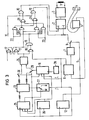
- FIG. 3 shows in more detail how, in the case of a device according to FIG. 2, the course of the actual speed of the positioner is determined during the acceleration phase of a positioning process and the corresponding digitized values are stored in RAM 13 as values of the braking curve for the subsequent braking phase of the positioning process will.
- An acceleration counter 25 and a brake counter 26 are primarily used in the device according to FIG. 3. Furthermore, a memory control circuit 27 is provided which generates the pulse sequences required for writing and reading the RAM in a known manner and between writing and reading between the two states is switchable. Furthermore, two switches 29 and 30 are provided, with the aid of which the digitized values of the actual speed of the positioner can be written into the RAM 13 or read from it.
- a counter is provided as a digital speed generator 16, which is advanced by a clock generator 28 and is reset by the cylinder pulses coming from the device 6.
- the speed of the positioner has to run in a time-optimally controlled positioning system according to a root function from the distance covered or from the target distance.
- the acceleration phase and the brake lie between the two root branches phase a functional part parallel to the abscissa, ie a phase of constant maximum speed.
- the corner points, ie the end of the acceleration phase and the beginning of the braking phase coincide.
- the end of the acceleration phase and the start of the braking phase are therefore essential for optimal positioning. Therefore, in the exemplary embodiment according to FIG.
- these points of the speed profile are determined by the device control at the beginning of a positioning process and the end of the acceleration phase in the acceleration counter 25), the start of the braking phase in the brake counter 26 and the value for the entire track difference to be covered in the track difference register 12 entered.
- the cylinder pulses from the output of position detector 6 are at the clock inputs of these three counters, which can consist, for example, of TTL modules of the type 74193.
- the status output of the acceleration counter 25, which emits a pulse when the counter reading reaches zero or when it overflows, is also present the memory drive circuit 27 for the RAM 13. This memory drive circuit 27 supplies the pulse sequences required for writing and reading the RAM 13. It is triggered by the cylinder pulses from the device 6 and can be switched from writing to reading by the status signal of the acceleration counter 25.
- the time course of the actual speed of the positioner is determined each time during the acceleration phase of a positioning process and the corresponding digitized values are stored in RAM 13 as values of the braking curve for the subsequent braking phase.
- the actual speed sensor 16 which in the example shown consists of a counter which is counted up by the clock pulses of a clock generator 28 and is reset by the cylinder pulses from the position detector 6.
- the counter 16 is reset with the trailing edge of the cylinder pulse when it leaves a lane and is started immediately thereafter.
- the current state of the counter is recorded and, triggered by the memory control circuit 27, transferred to the RAM 13 via the switch 29. With the trailing edge of the cylinder pulse of the track, the counter is cleared again and the measuring process starts again.
- the data outputs of the acceleration counter 25, which are connected to the address inputs of the RAM 13, are used for addressing those memory cells of the RAM 13 into which a respectively determined actual speed value is to be stored.
- the values of the actual speed determined by the actual speed sensor 16 are stored in the RAM 13 in descending order during the acceleration phase.
- the address for the first measured value is identical to the relative address of the end of the acceleration phase, the last measured value of the actual speed, on the other hand, is saved under address zero.
- this value must be assigned to the first measured value of the actual speed determined during the braking phase (reflection of the acceleration curve).
- the counting direction of the acceleration counter 25 is switched from counting down to counting up.
- the actual speed sensor 16 in turn serves to determine the actual speed of the positioner.
- the two switches 29 and 30 are switched by the signal at the status output of the acceleration counter 25.
- the measured values determined by the actual speed sensor, on the one hand, and the measured values from the acceleration phase read from the RAM 13, on the other hand reach the digital comparator 24, which, as described in connection with FIGS. 1 and 2, controls the brake current effected in the positioner 1.
- a positioning process proceeds as follows: Before the actual start of the movement of the positioner 1, the counters 12, 25 and 26 are loaded with the corresponding basic values of the speed profile and their counting direction is switched to downwards.
- the memory control circuit 27 is switched such that the pulse sequences for writing the RAM 13 are emitted at its output after the release. Since the data outputs of the acceleration counter 25 are located at the address inputs of the RAM 13, the values determined in the actual speed sensor 16 are stored in the RAM 13 in descending order after the start of the positioning process with each cylinder pulse that occurs.
- the counter 25 When the counter 25 reaches zero, which corresponds to the end of the acceleration phase, the acceleration Current switched off for the positioner, the memory control circuit 27 for the RAM 13 switched to reading and the outputs of the counter of the actual speed sensor 16 switched to the digital comparator 24 via the switch 29. In addition, the counter 16 and the acceleration counter 25 are blocked and the counting direction of the acceleration counter 25 is switched over from the downward to the upward direction in preparation for the addressing during the subsequent braking phase.
- the brake counter 26 switches to zero, which corresponds to the beginning of the braking phase, then the braking current and the counters previously blocked are released again. With each subsequent cylinder pulse, the values measured by the actual speed sensor 16 are entered on the one hand, and the setpoints read by the counter addressing, which are now opposed, and correspondingly assigned, on the other hand, are entered into the digital comparator 24. The braking current is then switched on or off depending on the result of the comparison of the two applied values.
- microprocessor More and more microprocessors are used to control a wide variety of processes in newer disk memories. If, for example, such a microprocessor, which is already present in a magnetic disk storage system, is also used according to the invention for determining the actual speed and for storing the values determined in this way, it is possible, for example, to save part of the logic elements shown in FIGS. 1, 2 and 3. Furthermore, it is then possible with such a microprocessor to additionally carry out diagnostic work which, when implemented in conventional hardware, represents a very considerable outlay.
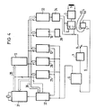
- FIG. 4 shows a schematic representation of a device according to the invention using a microprocessor system.
- the same parts were designated with the same reference numerals as in Figures 1, 2 and 3.
- the central unit 31 of a microprocessor for example a microprocessor of the type 8080 or 8085, an interrupt module 32 belonging to this system, an input / output module 33 and a control circuit 34 for the subsequent power amplifier, are present in the device according to FIG the digital signals supplied by the input / output module 33 generates the currents required for controlling the amplifiers 2 and 3 according to strength and polarity.
- the central processor 31 is via the address bus 35 on the one hand with the RAM 13 and on the other hand with the acceleration counter 25, the brake counter 26, the track difference register 12, the actual speed sensor 16 in the form of a measuring counter with a clock generator 23, and with the input / output module 33 and the interrupt block 32 connected.
- All of these are building blocks connected to the central processor 31 via a data bus 36 in a manner customary for microprocessor systems. The choice of the individual components naturally depends on the choice of the microprocessor system itself. If a processor 8080 or 8085 is used, the block 8253, for example, could be used as an acceleration, brake, track difference and measurement counter and block 8255 as an input / output block.
- the counters 12 ', 25 and 26 and the interrupt module 32 are clocked by the position detector device 6 in a manner similar to the device according to FIG. 3 by the cylinder pulses. As in the example of the device according to FIG. 3, the status outputs of these counters each provide a pulse when the counter reading reaches zero. These signals are connected to the interrupt request input of the processor module 31 with the aid of the interrupt module 32, which takes over the control of the individual interrupt signals (latching of short pulses, determination of the priority, etc.). These interrupt signals start the processing of the individual program sections.
- the track difference and the corner points of the speed profile are determined from the specified start and destination addresses.
- individual bits for the current direction, the positioning direction and the polarity of the target track are set from this data.
- the resulting values are then loaded into counters 12, 25 and 26, with the end of the acceleration phase being loaded into counter 25, the beginning of the braking phase into counter 26 and the track difference being loaded into counter 12, as in the device according to FIG .
- the start command for the positioning process the counters 12, 16, 25 and 26 are released and the acceleration current for the positioner 1 is switched on via the control circuit 34.
- interrupt module 32 starts a program in processor 31 which reads the current value of counter 16 and immediately resets this counter to zero.
- the read measured value is then subsequently stored in the assigned location in RAM 13. Then the counter 16 starts again until another cylinder pulse occurs. In this way, a measured value of the actual speed is determined with each cylinder pulse and stored in RAM 13. At the same time, the counters 12, 25 and 26 are counted down.
- the measured values of the counter 16 which occur with each subsequent cylinder pulse are, however, in the braking phase - by program - with the correspondingly assigned, recorded in the acceleration phase and stored in the RAM 13 stored target speed values compared.
- the braking current for the positioner is then switched on for a specific time (pulse duration modulation) during the next measuring cycle.
- the duty cycle for the braking current is also determined by the program.
- the interrupt triggered by the differential counter when the target track is reached causes the braking current to be switched off for the positioner 1, blocks all counters and switches on the fine control loop in a manner known per se.
- FIGS. 3 and 4 show a counter 16 in connection with a clock generator 28 as a device for generating a quantity which is proportional to the actual speed of the positioner. Instead, it would be entirely possible to use a speed sensor known per se, working on an analog basis, with a downstream analog / digital converter.
Landscapes
- Control Of Position Or Direction (AREA)
- Moving Of Heads (AREA)
- Moving Of Head For Track Selection And Changing (AREA)
Priority Applications (1)
| Application Number | Priority Date | Filing Date | Title |
|---|---|---|---|
| AT79102686T ATE462T1 (de) | 1978-07-31 | 1979-07-27 | Einrichtung zum regeln der geschwindigkeit eines positionierers fuer die schreib-/lesekoepfe eines magnetplattenspeichers. |
Applications Claiming Priority (2)
| Application Number | Priority Date | Filing Date | Title |
|---|---|---|---|
| DE19782833540 DE2833540A1 (de) | 1978-07-31 | 1978-07-31 | Einrichtung zum regeln der geschwindigkeit eines positionierers fuer die schreib-/lesekoepfe eines magnetplattenspeichers |
| DE2833540 | 1978-07-31 |
Publications (2)
| Publication Number | Publication Date |
|---|---|
| EP0007638A1 true EP0007638A1 (fr) | 1980-02-06 |
| EP0007638B1 EP0007638B1 (en) | 1981-12-02 |
Family
ID=6045848
Family Applications (1)
| Application Number | Title | Priority Date | Filing Date |
|---|---|---|---|
| EP79102686A Expired EP0007638B1 (en) | 1978-07-31 | 1979-07-27 | Device for regulating the speed of a positioner for the write/read heads of a magnetic disc memory |
Country Status (3)
| Country | Link |
|---|---|
| EP (1) | EP0007638B1 (fr) |
| AT (1) | ATE462T1 (fr) |
| DE (1) | DE2833540A1 (fr) |
Cited By (3)
| Publication number | Priority date | Publication date | Assignee | Title |
|---|---|---|---|---|
| EP0103493A1 (fr) * | 1982-09-15 | 1984-03-21 | Ampex Corporation | Générateur de commande de la vitesse réglé à deux échelons |
| EP0321886A1 (fr) * | 1987-12-21 | 1989-06-28 | Siemens Aktiengesellschaft | Procédé pour le positionnement à vitesse contrôlée d'une tête de lecture/écriture par rapport à un support d'enregistrement rotatif |
| US4868683A (en) * | 1986-06-24 | 1989-09-19 | Polygram International Holding B.V. | Method of aligning objects by detecting a reference picture line therein which has an optically characteristic picture content |
Families Citing this family (1)
| Publication number | Priority date | Publication date | Assignee | Title |
|---|---|---|---|---|
| US4486797A (en) * | 1982-11-22 | 1984-12-04 | International Business Machines Corporation | Sliding mask variable resolution velocity trajectory for track following servo |
Citations (3)
| Publication number | Priority date | Publication date | Assignee | Title |
|---|---|---|---|---|
| US3860861A (en) * | 1971-12-27 | 1975-01-14 | Potter Instrument Co Inc | Disk drive head positioning servo including temperature responsive safety means |
| FR2258661A1 (fr) * | 1974-01-18 | 1975-08-18 | Honeywell Bull Soc Ind | |
| US4086636A (en) * | 1977-02-28 | 1978-04-25 | Xerox Corporation | Restore method and apparatus for disk drive |
-
1978
- 1978-07-31 DE DE19782833540 patent/DE2833540A1/de not_active Withdrawn
-
1979
- 1979-07-27 EP EP79102686A patent/EP0007638B1/de not_active Expired
- 1979-07-27 AT AT79102686T patent/ATE462T1/de not_active IP Right Cessation
Patent Citations (3)
| Publication number | Priority date | Publication date | Assignee | Title |
|---|---|---|---|---|
| US3860861A (en) * | 1971-12-27 | 1975-01-14 | Potter Instrument Co Inc | Disk drive head positioning servo including temperature responsive safety means |
| FR2258661A1 (fr) * | 1974-01-18 | 1975-08-18 | Honeywell Bull Soc Ind | |
| US4086636A (en) * | 1977-02-28 | 1978-04-25 | Xerox Corporation | Restore method and apparatus for disk drive |
Non-Patent Citations (4)
| Title |
|---|
| IBM TECHNICAL DISCLOSURE BULLETIN, Vol. 16, Nr. 12, Mai 1974, Seiten 4064-4065 New York, U.S.A. R.D. COMMANDER et al.: "Disk File Track Access Control" * Seiten 4064-4065 * * |
| IBM TECHNICAL DISCLOSURE BULLETIN, Vol. 19, Nr. 7, Dezember 1976. Seiten 2686-2687 New York, U.S.A. D.E. BROWNBACK et al.: "Measuring and Adjusting Speed of Magnetic Disk Access Arm" * Seiten 2686-2687 * * |
| IBM TECHNICAL DISCLOSURE BULLETIN, Vol. 20, Nr. 12, Mai 1978, Seiten 5272-5280 New York, U.S.A. T.M. PASKA: "Digital Track Position Information Recording System" * Bild 5; Seite 5275, Zeile 11 - Seite 5280, Zeile 22 * * |
| IEEE TRANSACTIONS ON MAGNETICS, Vol. MAG-14, Nr. 4, Juli 1978, Seiten 182-184 New York, U.S.A. (IEEE Applied magnetics workshop on magnetic recording, San Francisco, U.S.A., 27-28 Juni 1978) B. MCKNIGHT: "A Track Locating Servo System Utilizing The Data Heads as Absolute Position Transducers" * Bild 3, Seite 183, linke Spalte, Zeilen 1-12 * * |
Cited By (3)
| Publication number | Priority date | Publication date | Assignee | Title |
|---|---|---|---|---|
| EP0103493A1 (fr) * | 1982-09-15 | 1984-03-21 | Ampex Corporation | Générateur de commande de la vitesse réglé à deux échelons |
| US4868683A (en) * | 1986-06-24 | 1989-09-19 | Polygram International Holding B.V. | Method of aligning objects by detecting a reference picture line therein which has an optically characteristic picture content |
| EP0321886A1 (fr) * | 1987-12-21 | 1989-06-28 | Siemens Aktiengesellschaft | Procédé pour le positionnement à vitesse contrôlée d'une tête de lecture/écriture par rapport à un support d'enregistrement rotatif |
Also Published As
| Publication number | Publication date |
|---|---|
| DE2833540A1 (de) | 1980-02-14 |
| ATE462T1 (de) | 1981-12-15 |
| EP0007638B1 (en) | 1981-12-02 |
Similar Documents
| Publication | Publication Date | Title |
|---|---|---|
| DE2909842C2 (de) | Schaltungsanordnung zur Steuerung der Geschwindigkeit eines von einem Elektromotor bewegbaren Elements eines Druckers | |
| DE4442112C2 (de) | Steuerverfahren zur Steuerung eines Aufzeichnungs-/Wiedergabekopfes | |
| DE69227434T2 (de) | Positionsregelsystem | |
| EP0151296B1 (fr) | Circuit de commande pour un moteur pas à pas | |
| DE3853154T2 (de) | Servokopf-Regelungsgerät. | |
| DE3875439T2 (de) | Digitale servosteuerung fuer plattengeraet. | |
| DE2550678A1 (de) | Spurauswahlanordnung in einem datenspeicher | |
| DE2626784B2 (de) | Numerische Steuervorrichtung | |
| DE3876157T2 (de) | Kopfpositioniersystem mit positionsfehlerkompensation. | |
| CH617030A5 (fr) | ||
| DE2932211C2 (fr) | ||
| DE2262430A1 (de) | Servosystem zum bewegen des magnetkopfes eines magnetspeichers | |
| DE3875124T2 (de) | Geraet fuer den antrieb optischer platten. | |
| DE2923296A1 (de) | Digitales servokontrollsystem | |
| CH621022A5 (fr) | ||
| DE3040527C2 (fr) | ||
| DE2850363C2 (de) | Direktzugriffsanordnung für ein Gerät zur Wiedergabe von Information von einem rotierenden Aufzeichnungsmedium | |
| DE69129018T2 (de) | Gerät zur kopfpositionssteuerung in einem plattenspeichergerät und verfahren zu dessen steuerung | |
| DE2264323A1 (de) | Verfahren und schaltungsanordnung zur steuerung der bremsung eines antriebs | |
| CH628300A5 (de) | Vorrichtung zum positionieren von teilen in einem flugzeug. | |
| DE3713397C2 (fr) | ||
| DE3927433C2 (fr) | ||
| DE2133079C2 (de) | Magnetplattenantrieb | |
| DE2143891A1 (de) | Einrichtung zum Steuern der Stellung zweier relativ zueinander bewegbarer Teile | |
| DE3939670C2 (fr) |
Legal Events
| Date | Code | Title | Description |
|---|---|---|---|
| PUAI | Public reference made under article 153(3) epc to a published international application that has entered the european phase |
Free format text: ORIGINAL CODE: 0009012 |
|
| AK | Designated contracting states |
Designated state(s): AT BE CH DE FR IT NL |
|
| 17P | Request for examination filed | ||
| ITF | It: translation for a ep patent filed | ||
| GRAA | (expected) grant |
Free format text: ORIGINAL CODE: 0009210 |
|
| STAA | Information on the status of an ep patent application or granted ep patent |
Free format text: STATUS: THE APPLICATION HAS BEEN WITHDRAWN |
|
| PUAC | Information related to the publication of a b1 document modified or deleted |
Free format text: ORIGINAL CODE: 0009299EPPU |
|
| AK | Designated contracting states |
Designated state(s): AT BE CH FR IT NL |
|
| REF | Corresponds to: |
Ref document number: 462 Country of ref document: AT Date of ref document: 19811215 Kind code of ref document: T |
|
| 18W | Application withdrawn |
Withdrawal date: 19811014 |
|
| DB1 | Publication of patent cancelled | ||
| REG | Reference to a national code |
Ref country code: CH Ref legal event code: PL |
|
| RIN1 | Information on inventor provided before grant (corrected) |
Inventor name: KUECHLER, WOLFGANG Inventor name: EITING, HERMANN |