EP0321886A1 - Procédé pour le positionnement à vitesse contrôlée d'une tête de lecture/écriture par rapport à un support d'enregistrement rotatif - Google Patents
Procédé pour le positionnement à vitesse contrôlée d'une tête de lecture/écriture par rapport à un support d'enregistrement rotatif Download PDFInfo
- Publication number
- EP0321886A1 EP0321886A1 EP88121167A EP88121167A EP0321886A1 EP 0321886 A1 EP0321886 A1 EP 0321886A1 EP 88121167 A EP88121167 A EP 88121167A EP 88121167 A EP88121167 A EP 88121167A EP 0321886 A1 EP0321886 A1 EP 0321886A1
- Authority
- EP
- European Patent Office
- Prior art keywords
- address
- read
- track
- positioning
- comparison
- Prior art date
- Legal status (The legal status is an assumption and is not a legal conclusion. Google has not performed a legal analysis and makes no representation as to the accuracy of the status listed.)
- Withdrawn
Links
- 238000000034 method Methods 0.000 title claims abstract description 41
- 230000015654 memory Effects 0.000 claims abstract description 17
- 230000001133 acceleration Effects 0.000 claims abstract description 15
- 230000007704 transition Effects 0.000 claims description 27
- 230000008569 process Effects 0.000 claims description 20
- 230000008859 change Effects 0.000 claims description 6
- 102100032757 Cysteine-rich protein 2 Human genes 0.000 claims description 4
- 101000942088 Homo sapiens Cysteine-rich protein 2 Proteins 0.000 claims description 4
- 101000851593 Homo sapiens Separin Proteins 0.000 claims description 4
- 230000001419 dependent effect Effects 0.000 claims description 2
- 238000010586 diagram Methods 0.000 description 4
- 230000001105 regulatory effect Effects 0.000 description 4
- 230000007423 decrease Effects 0.000 description 2
- 230000003247 decreasing effect Effects 0.000 description 2
- 238000006073 displacement reaction Methods 0.000 description 2
- 230000003287 optical effect Effects 0.000 description 2
- 238000012545 processing Methods 0.000 description 2
- 230000004044 response Effects 0.000 description 2
- 230000002123 temporal effect Effects 0.000 description 2
- 230000001052 transient effect Effects 0.000 description 2
- 239000000654 additive Substances 0.000 description 1
- 230000000996 additive effect Effects 0.000 description 1
- 230000006399 behavior Effects 0.000 description 1
- 230000008901 benefit Effects 0.000 description 1
- 238000004364 calculation method Methods 0.000 description 1
- 239000000969 carrier Substances 0.000 description 1
- 238000006243 chemical reaction Methods 0.000 description 1
- 238000013500 data storage Methods 0.000 description 1
- 238000011161 development Methods 0.000 description 1
- 230000018109 developmental process Effects 0.000 description 1
- 230000000694 effects Effects 0.000 description 1
- 230000002441 reversible effect Effects 0.000 description 1
- 230000003068 static effect Effects 0.000 description 1
- 238000012360 testing method Methods 0.000 description 1
- 238000013519 translation Methods 0.000 description 1
Images
Classifications
-
- G—PHYSICS
- G11—INFORMATION STORAGE
- G11B—INFORMATION STORAGE BASED ON RELATIVE MOVEMENT BETWEEN RECORD CARRIER AND TRANSDUCER
- G11B21/00—Head arrangements not specific to the method of recording or reproducing
- G11B21/02—Driving or moving of heads
- G11B21/08—Track changing or selecting during transducing operation
- G11B21/081—Access to indexed tracks or parts of continuous track
- G11B21/083—Access to indexed tracks or parts of continuous track on discs
Definitions
- the invention relates to a method according to the preamble of the main claim.
- Speed-controlled positioning methods are used in various technical fields, particularly also for read / write processes in data memories. Constantly increasing storage capacity can only be achieved with increased storage density, which is e.g. expresses in the increased number of information tracks per data disk. For this reason, a read / write head must always be positioned more precisely during write or read processes. In the interest of a short access time, however, the positioning process must be carried out as quickly as possible.
- a key feature of disk storage is the time it takes to position the read / write heads on a new track.
- a minimum positioning time means that the read / write head accelerates to a maximum speed at different positioning distances and then brakes to a target track within a very short time. This can be achieved by means of a speed-dependent control, for example of the motor current of a positioning motor that moves the read / write head.
- a speed-dependent control for example of the motor current of a positioning motor that moves the read / write head.
- a speed-controlled positioning method is therefore customary, in which the difference between a measured actual speed and a predetermined target speed regulates the current of the positioning motor.
- the positioning process takes place in three phases.
- an acceleration phase the read / write head is accelerated to a maximum target speed vmax with maximum motor current.
- the second phase the actual speed of the read / write head remains constant.
- the third phase is a braking phase, in which the actual speed of the read / write head is approximated to a changing target speed. The target speed values decrease according to a predetermined braking curve until the actual speed on the target track is zero.
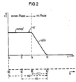
- the positioning process which runs perfectly in the manner described for larger positioning distances, proves to be problematic for small positioning distances.
- the constant phase initially shortens more and more, until finally the acceleration phase changes directly into the braking phase, with the maximum target speed value vmax no longer being reached.
- the direction of current in the positioning motor must be reversed at high power.
- the technically-related limited current rise rate, as well as settling processes due to the discontinuity of the control characteristic result in larger differences between the set and actual speeds.
- the trailing behavior of the control system can steer the motor current into saturation and then prevent a controlled positioning of the read / write head.
- a single braking curve with reduced braking power could be used.
- the braking curve must then be designed so that the motor current does not saturate in the braking phase at shorter positioning distances.
- the disadvantage of this is the reduced braking power with longer positioning distances and a consequent increase in the positioning time.
- Another option would be to use multiple braking curves for different positioning distances. This method would, however, be systematically complex. Depending on the positioning distance, the braking curve suitable for this distance should be selected. Another disadvantage would be the increased storage space required for the braking curves.
- a reversing control device allows the translationally movable system to be accelerated in free operation or uncontrolled during a first movement phase.
- a zero comparator With the help of a zero comparator, a reversal point is determined at which the acceleration phase changes into a second movement phase, the braking phase.
- the reversing control device continues to close a first control loop, thereby obtaining a control signal from a target / actual speed comparison.
- the reversal point is reached, this is fed to a generator to readjust the setpoint speed.
- the readjusted target speed is compared in a second control loop with the actual speed during the braking phase.
- the present invention is therefore based on the object of providing a method of the type mentioned at the outset with which a read / write head is positioned precisely on a recording medium in a very short time and without control problems, regardless of different positioning distances.
- This object is achieved in a method of the type mentioned by the features described in the characterizing part of the main claim.
- the positioning process is divided into a braking phase, a short transition phase that follows, and a braking phase that starts at a transition track.
- a three-phase control of the type mentioned the described shortcomings of known solutions can be avoided or eliminated.
- the solution is characterized in particular by the fact that for the speed-controlled positioning of the read / write head, regardless of the respective positioning distance, only a single stored braking curve is required, from which the target speed values for a target-actual speed comparison for speed control are taken.
- an address comparison between a comparison address and an actual address of the read / write head is carried out with each lane change, regardless of the respective movement state of the read / write head.
- the comparison address necessary for this comparison results from the transition track, the distance of which, for example, to the target track assumes a different value at each positioning distance.
- the actual address is the distance of the current position of the read / write head to the target track.
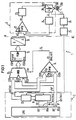
- a positioning device 1 as shown schematically in FIG. 1 in a block diagram, is suitable for carrying out a method for speed-controlled, translatory positioning of a read / write head 200 in relation to a rotating recording medium 21 with concentrically running information tracks 210.
- Positioning devices for data storage with rotating record carriers are generally known. It is therefore unnecessary to present and describe in detail the parts of such a device that are familiar to the person skilled in the art. Instead, for reasons of clarity and better understanding, only the functional blocks of the positioning device are shown in FIG. 1 which are essential for the invention.
- the positioning device for read / write heads 200 shown schematically in FIG. 1 is an electronically controlled mechanical device with an analog and digital component.
- the drive system can be designed as a linear or rotary positioner. In both cases, it has a permanent magnet (not shown) for generating a static magnetic field. In order to generate a variable magnetic field, a coil 201 of the drive system 20 is provided, through which a current i flows, which the power supply 23 supplies.
- the movement of the read / write head results from the mutual influence of the magnetic fields. Its actual speed vi is measured and by the speed keitswandler 24 converted into an electrical, the speed vi corresponding signal vi '. This signal is applied to an input of the comparator 22 and compared there with a speed signal vs' applied to a second input of the comparator. An error signal dv resulting from this is used to regulate the coil current.
- the speed signal vs' is generated digitally.
- the digital component of the positioning device shown on the left of the dividing line A ... B, has a central unit 10 which is connected to a track counter 11.
- the required number n of first signal lines X1... Xn depends on a number N of information tracks 210 on the recording medium 21. If the read / write head is now to be moved from a start track NS on the recording medium to a target track NZ, the the command necessary for this is passed on from a control unit of the central unit 10 to the track counter 11 via the signal lines X1 to Xn.
- the track counter is loaded with a target address xns at the beginning of the positioning process.
- the target address that is individual for each positioning process represents a target positioning distance nsz that the read / write head 200 travels from the start track NS to the destination track NZ.
- the track changes of the read / write head that are carried out are registered by a track following system 26 and converted by a position converter 25 into a track pulse spi corresponding to the track changes. With this track pulse, both the track counter and a one-memory flip-flop 12 are actuated in cycles and thus the content of the track counter that arises for each track change to the single-store flip-flop or simultaneously to the first switching inputs ES11 ... ES1n of a multiplexer 13 and to the first Comparison inputs EV11 ... EV1n of a comparator 14 passed on.
- the respective content of the track counter is composed of an actual address xni, which changes from one address to the other changing actual positioning distance niz for the read / write head 200 results.
- the actual positioning distance is determined from the difference between an actual track NI and the target track NZ. For each new actual track that the read / write head crosses, the counter reading of the track counter working in reverse mode is reduced by 1. At the end of the counting process, when the read / write head has reached the target track NZ, the counter is at zero.
- Both the multiplexer and the comparator each have second switching inputs ES21 ... ES2n or second comparison inputs EV21 ... EV2n, to which second signal lines Y1 ... Yn are connected.
- a comparison address ync generated by the central processing unit 10 is transmitted simultaneously to the multiplexer and to the comparator on these signal lines.
- the generated comparison address results from a positioning distance ncz, which indicates the distance between a transition track NC and the target track NZ.
- the transition track NC on the record carrier is the information track in which the read / write head changes from an acceleration phase v + to a braking phase v-.
- K1 9/16.
- K2 an additive constant K2 is also added. This takes into account the statistical relationship between the position of the transition track NC and the target positioning distance nsz. In many cases, however, it is sufficient for a still permissible, simplified description of the respective positioning process to set K2 to zero.
- the derived relationship is used as a basis for calculating the associated transition track for any desired positioning distance nsz in a computing unit of the central unit. Given the simplicity of this relationship, it does not appear necessary to describe the arithmetic unit and other components of the central processing unit necessary for the execution of arithmetic operations in detail. The implementation of such simple calculations with program-controlled systems is familiar to the person skilled in the art and is insignificant for understanding the invention.
- the value initially determined for each positioning process for the transition track NC is stored in a register (also not shown) and by indirect addressing output via the signal lines Y1 to Yn. Thus, the actual address xni is present at the first switching and comparison inputs of the multiplexer 13 or the comparator 14 and the comparison address ync is present at the second switching and comparison inputs.
- the comparator outputs a binary control signal dn with the signal states dn1 or dn0, with which the multiplexer is controlled.
- the comparison address ync at the second switching input ES21 ... ES2n of the multiplexer is switched through to a memory input ESP1 ... ESPn of a programmable read-only memory 15. If, on the other hand, the multiplexer is controlled by the control signal dn0, the actual address xni is switched through at the first switching input ES11 ... ES1n of the multiplexer. With the comparison address or actual address present at each of the memory inputs ESP1 ... ESPn of the programmable read-only memory, an individual maximum value vsmax ′ or a target speed value vs1 ...
- vsn is read from this and forwarded to a digital-to-analog converter 16 .
- the number of the desired speed values corresponds to the number N of information tracks 210 on the recording medium 21.
- the individual maximum value vsmax ′ is new for each positioning process.
- the respective maximum value is thus equal to the target speed value vs1 ... vsn, which corresponds to the transition track NC.
- the converted, analogized target speed signal vs' then serves, as already described, as a reference variable for the target / actual speed comparison on the comparator 22.
- the individual maximum value vsmax ' is applied to the control circuit 2. Only when the actual positioning distance niz is smaller than the distance ncz does the target speed value vs ′ on the comparator 22 change with each information track that is crossed by the read / write head 200.
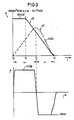
- FIG. 3 shows, for an "unregulated" positioning process, a set / actual speed curve with a corresponding coil current i.
- the illustration in FIG. 3 illustrates the physical processes in the control circuit 2.
- the coil is fed with a positive coil current i.
- a maximum setpoint speed value vsmax is applied to the input of the comparator up to a setpoint transition time tx, that is to say during the vsmax phase.
- Characteristic of the unregulated positioning process shown in FIG. 3 is the poor transient response of the measured actual speed profile vi 'with respect to the target speed profile vs' for times t greater than an actual transition time tc.
- the read / write head can no longer be positioned on the target track NZ due to the predefined setpoint speed profile vs' and the saturation property of the coil within an available braking time tz-tc.
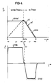
- FIG. 4 shows a setpoint-actual speed curve of a “regulated” positioning process.
- the vsmax phase is expanded and thus a much better transient response of the actual speed profile vi' to the target speed profile vs' is achieved.
- exact positioning of the read / write head over the information track NC is possible within the braking time tz-tc provided without the coil being driven into saturation at a current -imax.
- the method described has the advantage of requiring only one braking curve for different positioning distances when positioning a read / write head in relation to a record carrier. Compared to a method in which several braking curves are required, the method described requires a significantly smaller storage space. In addition, the method offers the possibility of using a single braking cure ve to perform the positioning of the read / write head with the greatest possible braking power. As already mentioned, this is noticeable in a shorter positioning time or access time. For the person skilled in the art, it is obvious from the above explanation of the exemplary embodiment of the invention that within the scope of the disclosed technical teaching, configurations are certainly possible which relate to any type of recording medium; eg magnetic, optical, magneto-optical storage disks, floppy discs.
- the recording media used for the described method have concentric information tracks.
- the method can also be used, for example, for pit structures arranged spirally on optical storage disks.
- the speed-controlled positioning of the read / write head within the scope of the disclosed technical teaching is completely micro-program-controlled, by also carrying out the address comparison and the address selection for the read-only memory using a micro-program.
Landscapes
- Moving Of Head For Track Selection And Changing (AREA)
Applications Claiming Priority (2)
| Application Number | Priority Date | Filing Date | Title |
|---|---|---|---|
| DE3743391 | 1987-12-21 | ||
| DE3743391 | 1987-12-21 |
Publications (1)
| Publication Number | Publication Date |
|---|---|
| EP0321886A1 true EP0321886A1 (fr) | 1989-06-28 |
Family
ID=6343183
Family Applications (1)
| Application Number | Title | Priority Date | Filing Date |
|---|---|---|---|
| EP88121167A Withdrawn EP0321886A1 (fr) | 1987-12-21 | 1988-12-16 | Procédé pour le positionnement à vitesse contrôlée d'une tête de lecture/écriture par rapport à un support d'enregistrement rotatif |
Country Status (1)
| Country | Link |
|---|---|
| EP (1) | EP0321886A1 (fr) |
Cited By (1)
| Publication number | Priority date | Publication date | Assignee | Title |
|---|---|---|---|---|
| EP0356939A1 (fr) * | 1988-08-25 | 1990-03-07 | Sharp Kabushiki Kaisha | Dispositif de commande d'une opération d'accès pour un appareil d'enregistrement et de lecture d'information |
Citations (7)
| Publication number | Priority date | Publication date | Assignee | Title |
|---|---|---|---|---|
| FR2125852A5 (fr) * | 1971-02-15 | 1972-09-29 | Ibm | |
| US3729668A (en) * | 1970-06-26 | 1973-04-24 | Honeywell Bull Soc Ind | Aparatus for controlling the displacement of an object between any two points |
| FR2172733A5 (fr) * | 1972-02-18 | 1973-09-28 | Philips Nv | |
| FR2258661A1 (fr) * | 1974-01-18 | 1975-08-18 | Honeywell Bull Soc Ind | |
| EP0007638A1 (fr) * | 1978-07-31 | 1980-02-06 | Siemens Aktiengesellschaft | Dispositif pour régler la vitesse d'un positionneur des têtes d'écriture et de lecture d'une mémoire à disque |
| US4491776A (en) * | 1982-05-25 | 1985-01-01 | Manhattan Engineering Company, Inc. | Servo operated digital positioning control system |
| US4622604A (en) * | 1983-05-23 | 1986-11-11 | Kabushiki Kaisha Toshiba | Magnetic head controlling apparatus |
-
1988
- 1988-12-16 EP EP88121167A patent/EP0321886A1/fr not_active Withdrawn
Patent Citations (7)
| Publication number | Priority date | Publication date | Assignee | Title |
|---|---|---|---|---|
| US3729668A (en) * | 1970-06-26 | 1973-04-24 | Honeywell Bull Soc Ind | Aparatus for controlling the displacement of an object between any two points |
| FR2125852A5 (fr) * | 1971-02-15 | 1972-09-29 | Ibm | |
| FR2172733A5 (fr) * | 1972-02-18 | 1973-09-28 | Philips Nv | |
| FR2258661A1 (fr) * | 1974-01-18 | 1975-08-18 | Honeywell Bull Soc Ind | |
| EP0007638A1 (fr) * | 1978-07-31 | 1980-02-06 | Siemens Aktiengesellschaft | Dispositif pour régler la vitesse d'un positionneur des têtes d'écriture et de lecture d'une mémoire à disque |
| US4491776A (en) * | 1982-05-25 | 1985-01-01 | Manhattan Engineering Company, Inc. | Servo operated digital positioning control system |
| US4622604A (en) * | 1983-05-23 | 1986-11-11 | Kabushiki Kaisha Toshiba | Magnetic head controlling apparatus |
Non-Patent Citations (1)
| Title |
|---|
| IBM TECHNICAL DISCLOSURE BULLETIN, Band 26, Nr. 3B, August 1983, Seiten 1741-1742, New York, US; D.H. PENNINGTON et al.: "Digital velocity reference curve anticipator" * |
Cited By (1)
| Publication number | Priority date | Publication date | Assignee | Title |
|---|---|---|---|---|
| EP0356939A1 (fr) * | 1988-08-25 | 1990-03-07 | Sharp Kabushiki Kaisha | Dispositif de commande d'une opération d'accès pour un appareil d'enregistrement et de lecture d'information |
Similar Documents
| Publication | Publication Date | Title |
|---|---|---|
| DE3404205C2 (de) | Steuereinrichtung für ein Flüssigkeitsventil | |
| CH617030A5 (fr) | ||
| DE2131699A1 (de) | Anordnung zur Verstellung eines Gegenstandes nach einem vorgegebenen Bewegungsgesetz | |
| DE1044471B (de) | Schaltungsanordnung zur Markierung von Kreuzungspunkten einer Widerstand-Dioden-Matrix | |
| DE2143891A1 (de) | Einrichtung zum Steuern der Stellung zweier relativ zueinander bewegbarer Teile | |
| DE2215045A1 (de) | Servo-Steuerung für die Einstellung eines Magnetkopfes | |
| DE2722848A1 (de) | Motor-antriebssteuerung | |
| DE3927433A1 (de) | Positioniersteuervorrichtung | |
| DE2501792A1 (de) | Anordnung zum regeln der verschiebung und positionierung eines translatorisch beweglichen systems | |
| DE3731984A1 (de) | Verfahren zur adaptiven stellregelung bei elektro-mechanischen antrieben | |
| DE2219692B2 (fr) | ||
| DE2048348A1 (de) | Verfahren und Vorrichtung zum Andern des Verstarkungsgrades eines digitalen Steuersystems | |
| EP0321886A1 (fr) | Procédé pour le positionnement à vitesse contrôlée d'une tête de lecture/écriture par rapport à un support d'enregistrement rotatif | |
| DE2044736C2 (de) | Anordnung zur Regelung der Geschwindigkeit zwischen zwei relativ zueinander bewegbaren Teilen | |
| DE1563594C3 (de) | Numerisch arbeitende Programmsteuerungsanordnung zur Stetigbahnsteuerung von Arbeitsmaschinen, insbesondere Werkzeugmaschinen | |
| DE1588783A1 (de) | Stromrichter | |
| DE3723280C2 (fr) | ||
| DE2544235A1 (de) | Schaltungsanordnung zum in-phase- bringen eines servoantriebes fuer ein rotierendes system | |
| DE4208684C2 (de) | Videorekorder mit einer Vorrichtung zur Steuerung eines Kopftrommelwinkels und ein entsprechendes Verfahren | |
| DE19635981C2 (de) | Verfahren zur direkten Regelung der Geschwindigkeit eines elektrischen Antriebes | |
| DE3437954A1 (de) | Verfahren zur ansteuerung eines schrittmotors | |
| DE3241400A1 (de) | Verfahren und einrichtung zur fortlaufenden aufzeichnung von informationssignalen vorbestimmter laenge auf eine magnetspeicherspur | |
| EP0007638A1 (fr) | Dispositif pour régler la vitesse d'un positionneur des têtes d'écriture et de lecture d'une mémoire à disque | |
| DE19852037A1 (de) | Magnetbandgerät mit Treiberschaltung für Matrixkopf | |
| DE2554018C2 (de) | Servoschaltung für die Einstellung eines Magnetkopfes auf eine ausgewählte Datenspur eines Magnetplattenspeichers |
Legal Events
| Date | Code | Title | Description |
|---|---|---|---|
| PUAI | Public reference made under article 153(3) epc to a published international application that has entered the european phase |
Free format text: ORIGINAL CODE: 0009012 |
|
| AK | Designated contracting states |
Kind code of ref document: A1 Designated state(s): AT CH DE FR GB IT LI NL |
|
| 17P | Request for examination filed |
Effective date: 19890726 |
|
| 17Q | First examination report despatched |
Effective date: 19910610 |
|
| STAA | Information on the status of an ep patent application or granted ep patent |
Free format text: STATUS: THE APPLICATION HAS BEEN WITHDRAWN |
|
| 18W | Application withdrawn |
Withdrawal date: 19911010 |
|
| R18W | Application withdrawn (corrected) |
Effective date: 19911010 |