EP0007770A1 - Machine à imprimer - Google Patents
Machine à imprimer Download PDFInfo
- Publication number
- EP0007770A1 EP0007770A1 EP79301421A EP79301421A EP0007770A1 EP 0007770 A1 EP0007770 A1 EP 0007770A1 EP 79301421 A EP79301421 A EP 79301421A EP 79301421 A EP79301421 A EP 79301421A EP 0007770 A1 EP0007770 A1 EP 0007770A1
- Authority
- EP
- European Patent Office
- Prior art keywords
- tape
- printing
- spool
- take
- printing machine
- Prior art date
- Legal status (The legal status is an assumption and is not a legal conclusion. Google has not performed a legal analysis and makes no representation as to the accuracy of the status listed.)
- Withdrawn
Links
- 229920003023 plastic Polymers 0.000 claims abstract description 5
- 239000004033 plastic Substances 0.000 claims abstract description 5
- 238000004804 winding Methods 0.000 claims description 8
- 238000003825 pressing Methods 0.000 claims description 5
- 230000000694 effects Effects 0.000 claims description 4
- 230000008961 swelling Effects 0.000 description 4
- 239000004698 Polyethylene Substances 0.000 description 1
- 239000000463 material Substances 0.000 description 1
- 230000000116 mitigating effect Effects 0.000 description 1
- 230000000149 penetrating effect Effects 0.000 description 1
- -1 polyethylene Polymers 0.000 description 1
- 229920000573 polyethylene Polymers 0.000 description 1
Images


Classifications
-
- B—PERFORMING OPERATIONS; TRANSPORTING
- B41—PRINTING; LINING MACHINES; TYPEWRITERS; STAMPS
- B41K—STAMPS; STAMPING OR NUMBERING APPARATUS OR DEVICES
- B41K3/00—Apparatus for stamping articles having integral means for supporting the articles to be stamped
- B41K3/54—Inking devices
- B41K3/58—Inking devices using ink ribbons, ink sheets, or carbon tape or paper
-
- B—PERFORMING OPERATIONS; TRANSPORTING
- B41—PRINTING; LINING MACHINES; TYPEWRITERS; STAMPS
- B41F—PRINTING MACHINES OR PRESSES
- B41F31/00—Inking arrangements or devices
- B41F31/16—Continuous, e.g. endless, band apparatus
Definitions
- This invention relates to printing machines.
- a row of printing characters is pressed against the tape at the printing station, and on release of pressure the tape generally remains in engagement with the characters.
- the force needed to release the tape from the character is small, but for a row of characters, the force required can be substantial. If the force is applied suddenly, tape may unspool from the supply spool, or the tape may tear or break, and accordingly it is necessary to distribute the force in some way.
- the configuration is such that, as the amount of tape wound onto the take-up spool increases, the plane of the tape passing from the print station to the take-up spool lies more nearly in the plane of the row of printing characters and the force needed to release the tape from the characters increases.
- the take-up spool becomes swollen; that is, it has a larger diameter for a given length of tape wound thereon than the diameter of a supply spool supporting the same length of tape. Swelling may be caused by loose winding of tape onto the take-up spool. Also, the tape becomes embossed by impact of the printing characters which, particularly in association with loose winding, can cause substantial swelling. Such swelling should be avoided if possible. First, it can render the force needed to release tape from the characters unnecessarily large as described above.
- the tape As the diameter of the take-up spool increases, and particularly if the tape is being tightly wound onto the spool, the tape has a tendency to move axially during winding.
- Tape is wasted if the take-up spool is incremented through a fixed angle between printing strokes, and the wastage increases as the diameter of the tape on the take-up spool increasrs. Consequently it is preferable to wind tape onto the take-up spool in equal increments.
- the present invention consists in a printing machine comprising a printing station and a printing device for presenting a row of printing characters to the printing station; a supply spool and take-up spool with a thin plastic inked tape extending therebetween by way of the printing station; means for applying pressure between the row of printing characters and a document fed to the printing station so that an impression of said row is delivered by the tape to the document during dwell of the tape at the printing station; and a drive means for incrementally winding said tape from the supply spool onto the take-up spool, characterized in that the drive means comprises a generally cylindrical rotatable indexing member provided with a circular series of projections extending around the circumference of the member and the axis of rotation of the member extending parallel with the axis of rotation of the take-up spool, and biassing means biassing, in operation, the indexing member into driving engagement with tape on the take-up spool with sufficient force to penetrate several layers of tape so that tape in the outer layer perforated by
- the indexing member is provided with two circular series of projections extending around the circumference of the member.
- Mitigation of various of the problems described above, such as the axial movement of tape on the take-up spool, may be assisted by the indexing member having the two series of projections situated in relation to the take-up spool at locations equally spaced from the centre-line of tape on the take-up spool, and preferably, each series has the same number of projections and each projection in the second series lies on a line parallel to the axis of rotation of the member through a respective projection in the first series.
- the drive means comprises a reciprocable driving mechanism whereby the indexing member is driven in one sense only and through a predetermined angle by each reciprocation of the driving mechanism, so that the indexing member effects winding onto the take-up spool of equal increments of tape upon respective reciprocations of the driving mechanism.
- the means for applying pressure between the row of printing characters and a document fed to the printing station comprise an impression wheel rotatably mounted on a shaft carried at respective ends thereof on parallel endless bands driven by powered wheel means in engagement with one at least of said bands, the ends of the shaft when traversing the upper run of the endless bands resiliently engaging respective rails as the impression wheel performs a printing stroke.
- the shaft of the impression wheel at the completion of each printing stroke actuates the reciprocable driving mechanism.
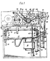
- the drawings illustrate a printing machine comprising a printing station 13 and a printing device in the form of printing box 12.
- a print table 15 to which documents to be printed, for example cheques or lottery tickets, are fed.
- the printing box 12 is a number wheel counter of known form and presents a row of printing characters at the printing station for forming a printing impression on a document fed to print table 15. After each printing stroke the counter is advanced to change one or more characters of the row as hereinafter indicated.
- the printing machine further comprises a supply spool 3 on which tape 1 is held in a known manner by a tape tensioning spring, not shown, and a take-up spool 5.
- the tape is thin and consists of a plastic, for example polyethylene, coated with ink on one side thereof, the term "ink” being employed herein to designate any fom of marking material.
- the tape 1 extends with the inked side thereof facing downwardly, from supply spool 3, around guide 7, beneath a lower member 11 of the printing box 12 which provides a horizontal run of tape at printing station 13, and around guide 9 to 'the take-up spool 5.
- the tape passes between print table 15 and lower member 11.
- Beneath print table 15 is provided a printing impression wheel 17 for applying pressure between the row of printing characters presented by printing box 12 and a document fed to the printing station 13, so that an impression of the row. is delivered by the inked tape to the document during dwell of the tape at the printing station.
- the impression wheel 17 projects through a slot in the print table to press the document to be printed against the row of printing characters, and to this end wheel 17 is rotatably mounted on a transverse shaft 19 the ends of which are secured to respective parallel endless chains 21 each of which passes over a pair of guide sprockets 23.
- a roller 25 carrying a resilient tyre 27.
- the tyres 27 press on the rails 29 and cushion the force between the wheel 17 and the row of printing characters presented by printing box 12 so that the likelihood of damage to the characters is reduced.
- characters are provided in bar coded form it is most important to prevent damage to the characters which could result in failure to print the bar code in a form which could be correctly read.
- the cushioning of the printing stroke could be effected in other ways, for example, by having a resilient mounting of the printing box on the machine frame or by having the impression wheel 17 resiliently mounted on the shaft 19.
- the chains 21 are driven from an electric motor 30 which by way of a gear box 32 drives a pulley 33 the latter being coupled by means of a belt 35 to a further pulley 37.
- a gear box 32 drives a pulley 33 the latter being coupled by means of a belt 35 to a further pulley 37.
- Rotatable with the further pulley 37 is a pair of sprockets 39 which are connected by a cross shaft 41 and which engage the lower run of the respective chains 21 and tension and drive the same.
- the shaft 19 as it passes around sprockets 23 from the upper to the lower run of the chains 21 effects reciprocation of a reciprocable driving mechanism for the purpose of indexing the take-up spool 5 as hereinafter described.
- the reciprocable driving mechanism includes an upright rod 43 pivotally mounted at its lower end in a support 45 and having an upper part disposed in the path of the shaft 19.
- a further horizontally disposed rod 47 is pivotally supported in a support 49 located at the side of the machine opposite the motor driven belt 35 and extends through a horizontal slot 51 in the side of the machine adjacent the belt 35.
- the end of the rod 47 which projects through the slot 51 is pivoted to a forward end of a link 53 a rearward end of which is pivotally connected to a bell crank 55 which is pivotally supported at 57 on the side of the machine.
- a tension spring 59 connected between the bell crank 55 and the side of the machine biasses the bell crank upwardly which in turn biasses the link 53 rearwardly and further biasses the rod 47 into engagement with upright rod 43 and with the forward end of the slot 51.
- an upwardly extending link 58 which is formed with bifurcations 60 in an upper part thereof and between which is pivotally secured an arm 61 which is secured to a shaft 63 which extends parallel with the axes of the supply and take-up spools 3 and 5 so that reciprocation of the end of the arm 61 secured to link 58, which occurs each time, when at the end of a printing stroke,the rod 43 is engaged by the transverse shaft 19, effects rotary reciprocation of the shaft 63.
- a crank 65 Secured to the shaft 63 is a crank 65 formed with holes 67 which enable the throw of the crank to be adjusted. Attached to one of the holes 67 is one end of a cord 69 which passes round a pulley 71 of a clutch 73 and the other end of which is attached to an end of a tension spring 74 the opposite end of which is anchored to the side of the machine.
- the clutch 73 has an output member secured to a shaft 75 which extends parallel with the spools 3 and 5 and the clutch provides a one-way drive means for the shaft 75 which is rotated through a constant angle, which depends on the throw of the crank 65 after each printing stroke.
- the shaft 75 is pendently supported from the top of the machine by means of drop links 77 secured to the shaft and pivoted to an upper parallel rod 79 mounted by members 80 from the top of the machine.
- the structure comprising the clutch 73, shaft 75 and links 77 is biassed towards the take-up spool 5 by means of a tension spring 81, the opposite ends of which are connected to respective anchorages 83, 85 on the body of the machine and secured relative to the shaft 75.
- a cylindrical indexing member 87 is mounted on shaft 75 for rotation therewith at a location facing tape wound onto the take-up spool 5 so that the axis of rotation of member 87 extends parallel with the axis of rotation of the take-up spool. Extending around the circumference of the member are two circular series 88 and 90 of projections 89. Biassing means comprising spring 81 biasses the member into driving engagement with tape on the take-up spool with sufficient force to penetrate several layers of tape so that tape in the outer layer perforated by a projection extends through apertures in inner layers formed by the projection thereby fixedly securing the outer layer relative to the inner layers.
- the take-up spool 5 comprises a cardboard former (not shown) and prior to several turns of tape having accumulated on the former the projections 89 penetrate the few turns of tape on the former and the former itself.
- the two series of projections are situated in relation to the take-up spool at locations equally spaced from the centre-line of tape on the take-up spool.
- Each series has the same number of projections 89 and each projection in series 88 lies on a line parallel to the axis of rotation of member 87 through a respective projection in series 90.
- the spacing of projections in each series is such that, even when the diameter of tape on the take-up spool is small, two projections penetrating the tape, one from each series, are not withdrawn from the top few layers of tape as the indexing member rotates until the next two succeeding projections have perforated and formed apertures in more than one layer of the tape.
- the reciprocable driving mechanism drives the indexing member in one sense only and through a predetermined angle during each reciprocation, and the positive driving connection afforded between the indexing member 87 and tape on the take-up spool ensures that after each printing stroke equal lengths of tape are wound onto the take-up spool, and wastage of tape is avoided.
- member . 87 is withdrawable from the take-up spool.
- a collar 91 is secured to the shaft 75 and fixed to the collar is a handle 93 comprising a rod 95 fixed at one end to the collar, a knob 97 at the end of the rod 95 opposite the collar, a short sleeve 99 fixed to the rod and a stop collar 101 secured to the sleeve 99.
- the stop collar 101 limits travel of the indexing member towards the take-up spool.
- the sleeve 99 is moved to a position where its inner end is located outside the keyhole slot so that the knob 97 can then be lowered and released to bring the inner end of the sleeve 99 into abutting relationship with the narrower part of the keyhole slot aperture in which position the indexing member 87 is held with its projections withdrawn from tape on thetake-up spool. Raising of the knob 97 restores the indexing member 87 to its original operative position under the influence of tension spring 81.
- a further crank 106 Secured to the shaft 63 is a further crank 106 which is connected pivotally to an end of a horizontal link 107 the opposite end of which pivotally connects with one end of an arm 109 which is pivotally secured intermediate its ends to the side of the machine and at the end thereof remote from the link 107 is formed with a fork 111.
- the fork 111 engages an element on an end of a lever 113 which pivots about an axis co-axial with the number wheels of the counter mechanism forming the printing box 12.
- the spools 3 and 5 can if desired be provided in the form of a cassette for ready replacement.
- the documents to be printed may be stored in a stack in a supply mechanism fixed to the machine which causes one document at a time to be supplied to the printing station.
- a discharge mechanism is also provided which removes the document from the printing station after printing.
Landscapes
- Impression-Transfer Materials And Handling Thereof (AREA)
Applications Claiming Priority (2)
| Application Number | Priority Date | Filing Date | Title |
|---|---|---|---|
| GB7830488 | 1978-07-20 | ||
| GB3048878 | 1978-07-20 |
Publications (1)
| Publication Number | Publication Date |
|---|---|
| EP0007770A1 true EP0007770A1 (fr) | 1980-02-06 |
Family
ID=10498544
Family Applications (1)
| Application Number | Title | Priority Date | Filing Date |
|---|---|---|---|
| EP79301421A Withdrawn EP0007770A1 (fr) | 1978-07-20 | 1979-07-17 | Machine à imprimer |
Country Status (2)
| Country | Link |
|---|---|
| EP (1) | EP0007770A1 (fr) |
| FI (1) | FI792239A7 (fr) |
Citations (3)
| Publication number | Priority date | Publication date | Assignee | Title |
|---|---|---|---|---|
| DE391928C (de) * | 1921-09-23 | 1924-03-13 | Charles Ashton Henry Bullock | Druckpresse mit einem endlosen Foerdermittel fuer die im Kreislauf um die Druckform gefuehrten Druck- und Farbwalzen und den Bogenausleger |
| US3134324A (en) * | 1962-04-20 | 1964-05-26 | Martin Machine Co Inc | Roller printing apparatus |
| US3217638A (en) * | 1963-12-30 | 1965-11-16 | Gottscho Inc Adolph | Hot die roll leaf marking apparatus |
-
1979
- 1979-07-17 EP EP79301421A patent/EP0007770A1/fr not_active Withdrawn
- 1979-07-17 FI FI792239A patent/FI792239A7/fi not_active Application Discontinuation
Patent Citations (3)
| Publication number | Priority date | Publication date | Assignee | Title |
|---|---|---|---|---|
| DE391928C (de) * | 1921-09-23 | 1924-03-13 | Charles Ashton Henry Bullock | Druckpresse mit einem endlosen Foerdermittel fuer die im Kreislauf um die Druckform gefuehrten Druck- und Farbwalzen und den Bogenausleger |
| US3134324A (en) * | 1962-04-20 | 1964-05-26 | Martin Machine Co Inc | Roller printing apparatus |
| US3217638A (en) * | 1963-12-30 | 1965-11-16 | Gottscho Inc Adolph | Hot die roll leaf marking apparatus |
Also Published As
| Publication number | Publication date |
|---|---|
| FI792239A7 (fi) | 1981-01-01 |
Similar Documents
| Publication | Publication Date | Title |
|---|---|---|
| US4440514A (en) | Adjustable ribbon feed rates dependent upon ribbon type for ink ribbon cassettes | |
| JP3498844B2 (ja) | リボンのテンション維持方法及び装置 | |
| CA1130748A (fr) | Entrainement de ruban a galet de renvoi avec ressort antagoniste | |
| JPH042502B2 (fr) | ||
| JP2544485B2 (ja) | プリンタ | |
| GB1565514A (en) | Ribbon transport | |
| US4027765A (en) | Record media drive mechanism | |
| US3065691A (en) | Printing and die cutting machine | |
| US4018153A (en) | Tape handling apparatus utilizing tangential web contact for postage meter | |
| GB2025854A (en) | Printing Machine | |
| US4165191A (en) | Web feed, web cutting and ribbon feed means for a stationery mosaic printer | |
| GB1585979A (en) | Typewriter ribbon feed and lift mechanism | |
| US3902412A (en) | Apparatus for printing and severing labels | |
| US3915276A (en) | Belt printer | |
| US3256813A (en) | Strip material winding machine | |
| FR2623127A1 (fr) | Dispositif d'alimentation et de reception d'une bande continue destine aux presses a imprimer du type feuille a feuille | |
| US4319850A (en) | Method and means for storing typing ribbon | |
| JP3689317B2 (ja) | 刻印装置 | |
| US4052936A (en) | Printing apparatus | |
| US1732908A (en) | Machine for applying pasters to folders and the like | |
| US2248188A (en) | Manifolding device | |
| US677821A (en) | Label-printing machine. | |
| US4840507A (en) | Printer with printing shield | |
| US4255997A (en) | Label machine | |
| DE2064183C3 (de) | Handetikettiergerät |
Legal Events
| Date | Code | Title | Description |
|---|---|---|---|
| PUAI | Public reference made under article 153(3) epc to a published international application that has entered the european phase |
Free format text: ORIGINAL CODE: 0009012 |
|
| AK | Designated contracting states |
Designated state(s): DE FR GB SE |
|
| DET | De: translation of patent claims | ||
| 17P | Request for examination filed | ||
| STAA | Information on the status of an ep patent application or granted ep patent |
Free format text: STATUS: THE APPLICATION IS DEEMED TO BE WITHDRAWN |
|
| 18D | Application deemed to be withdrawn |
Effective date: 19820513 |
|
| RIN1 | Information on inventor provided before grant (corrected) |
Inventor name: PUESCHEL, JOHANNES |