EP0007914A1 - Handbetriebene abstimmvorrichtung - Google Patents
Handbetriebene abstimmvorrichtung Download PDFInfo
- Publication number
- EP0007914A1 EP0007914A1 EP79900106A EP79900106A EP0007914A1 EP 0007914 A1 EP0007914 A1 EP 0007914A1 EP 79900106 A EP79900106 A EP 79900106A EP 79900106 A EP79900106 A EP 79900106A EP 0007914 A1 EP0007914 A1 EP 0007914A1
- Authority
- EP
- European Patent Office
- Prior art keywords
- channel selection
- output
- upward
- downward
- manual channel
- Prior art date
- Legal status (The legal status is an assumption and is not a legal conclusion. Google has not performed a legal analysis and makes no representation as to the accuracy of the status listed.)
- Withdrawn
Links
Images

Classifications
-
- H—ELECTRICITY
- H03—ELECTRONIC CIRCUITRY
- H03J—TUNING RESONANT CIRCUITS; SELECTING RESONANT CIRCUITS
- H03J7/00—Automatic frequency control; Automatic scanning over a band of frequencies
- H03J7/18—Automatic scanning over a band of frequencies
- H03J7/20—Automatic scanning over a band of frequencies where the scanning is accomplished by varying the electrical characteristics of a non-mechanically adjustable element
- H03J7/24—Automatic scanning over a band of frequencies where the scanning is accomplished by varying the electrical characteristics of a non-mechanically adjustable element using varactors, i.e. voltage variable reactive diodes
- H03J7/26—Automatic scanning over a band of frequencies where the scanning is accomplished by varying the electrical characteristics of a non-mechanically adjustable element using varactors, i.e. voltage variable reactive diodes in which an automatic frequency control circuit is brought into action after the scanning action has been stopped
-
- H—ELECTRICITY
- H03—ELECTRONIC CIRCUITRY
- H03J—TUNING RESONANT CIRCUITS; SELECTING RESONANT CIRCUITS
- H03J5/00—Discontinuous tuning; Selecting predetermined frequencies; Selecting frequency bands with or without continuous tuning in one or more of the bands, e.g. push-button tuning, turret tuner
- H03J5/02—Discontinuous tuning; Selecting predetermined frequencies; Selecting frequency bands with or without continuous tuning in one or more of the bands, e.g. push-button tuning, turret tuner with variable tuning element having a number of predetermined settings and adjustable to a desired one of these settings
- H03J5/0245—Discontinuous tuning using an electrical variable impedance element, e.g. a voltage variable reactive diode, in which no corresponding analogue value either exists or is preset, i.e. the tuning information is only available in a digital form
- H03J5/0254—Discontinuous tuning using an electrical variable impedance element, e.g. a voltage variable reactive diode, in which no corresponding analogue value either exists or is preset, i.e. the tuning information is only available in a digital form the digital values being transfered to a D/A converter
-
- H—ELECTRICITY
- H03—ELECTRONIC CIRCUITRY
- H03J—TUNING RESONANT CIRCUITS; SELECTING RESONANT CIRCUITS
- H03J7/00—Automatic frequency control; Automatic scanning over a band of frequencies
- H03J7/02—Automatic frequency control
- H03J7/04—Automatic frequency control where the frequency control is accomplished by varying the electrical characteristics of a non-mechanically adjustable element or where the nature of the frequency controlling element is not significant
- H03J7/06—Automatic frequency control where the frequency control is accomplished by varying the electrical characteristics of a non-mechanically adjustable element or where the nature of the frequency controlling element is not significant using counters or frequency dividers
Definitions
- This invention concerns a channel selection apparatus adapted to facilitate manual channel selection in electronic tuning radio receivers.
- Electronic channel selection can be attained using voltage-variable type reactance elements in tuning circuits of a radio receiver and providing a control voltage generation circuit therefor, and the channel selection can be realized such as by a search channel selection system adapted to sweep the entire receiving frequency band from one direction or another direction ⁇ specifically, by the changes in a control voltage), stop the sweeping when a broadcasting station is caught and enter into receiving as it is if the station is a desired one or start the sweeping again by the push of a pushbutton if the station is not a desired one, a digital channel selection system adapted to set the frequency for a desired broadcasting station previously in a digital manner and change the receiving frequency as far as the receiving frequency reaches the set frequency, or a manual channel selection system adapted to manually maintain the gradual increase or decrease in a control voltage till a desired broadcasting station is caught, and the applicant has already proposed various types of channel selection apparatus such as "Digital Setting Receiver" in Japanese Patent
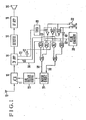
- a gate circuit for the control of an input signal to a voltage source which supplies a bias voltage to variable reactance elements in an electronic tuning radio receiver and, upon reception of a broadcasting wave, an input signal from a manual channel selection switch is temporarily interrupted and, instead, an AFC signal is inputted. This interrupts the frequency sweeping to enable a radio audience to clearly hear the broadcasting and judge whether it is a desired one or not.
- a receiving antenna 10 for supplying a bias voltage (control voltage) - to the above variable reactance element, consists of an integrating circuit (capacitor charge and discharge circuit) and outputs the above bias voltage which gradually increases upon input of a positive voltage and gradually decreases upon input of a negative voltage.
- the switching circuit 24 is a switching circuit, which issues the above positive voltage upon input of an upward signal from a lead 68 and output the above negative voltage upon input of a downward signal from a lead 70.
- the switching circuit is, in principle, composed of a positive and a negative voltage sources and a switching element turned ON and OFF with the above upward and downward signals and, actually, consists of ' a digital multiplexer or the like for switching signals in each of the foregoing various types of channel selection systems.
- Reference numerals 30, 32, 34 and 36 are AND gates, 38 and 40 are NOR gates, 42, 44 and 46 are inverters, 48 is a timer, 50 is a pulse generator and 52 and 54 are manual channel selection switches for each of the upward and downward directions.
- switches are grounded at one of their terminals to the earth, while the other terminal of the switch 52 is connected by way of the inverter 44 to one input terminal of the AND gate 32 and directly to one input terminal of the NOR gate 40, and the other terminal of the switch 54 is connected by way of the inverter 46 to one input terminal of the AND gate 36 and directly to the other input terminal of the NOR gate 40.
- the output of the timer 48 is connected by way of a lead 60 to the AND gates 32 and 36 and also to the NOR gate 38.
- the output of the pulse generator 50 is connected by way of a lead 62 . to the AND gates 32 and.36.
- the intermediate frequency amplifying stage 14 issues an intermediate frequency output, which is turned to "L" level upon reception of a broadcasting wave, through a lead 72 connected to its AVC terminal, and also issues an AFC (automatic frequency control) signal for instructing the frequency upwarding through a lead 64 and an AFC signal for instructing the signal downwarding through a lead 66.
- AFC automatic frequency control
- the pulse voltage is inputted to the variable reactance element bias source 22 causing it to generate a decreasing bias voltage Vb which is decreased by one step on every arrival of one pulse as shown in Fig. 3.
- the bias voltage Vb is applied to the variable reactance element such as a voltage variable reactance diode in the tuning circuits, increases its reactance value and thereby drives the tuning frequency, that is, the receiving frequency downwardly. The manual channel selection is thus started.
- An "L” level signal of the intermediate frequency output from the intermediate frequency amplifying stage 14 (this may be the output from a discriminator), which is at "H” level when no broadcasting wave is received and inverted by the inverter 42, is inputted to the second terminals of these AND gates. Consequently, these gates 30 and 34 are closed.
- the intermediate frequency output from the intermediate frequency amplifying'stage 14 turns to "L" level as shown in Fig. 2(2).
- the timer 48 produces an output which falls in timing with the fall of the output (2) and remains at "L" level for a certain period Ta as shown in Fig. 2(3). Since the "L" level output from the timer 48 is applied by way of the lead 60 to the AND gates 32 and 36, the AND gate 36 is closed to cease the issue of the pulses 63 from the pulse generator circuit 50 as shown in Fig. 2(4). This interrupts the increase in the bias voltage Vb and the channel selecting operation is interrupted temporarily.
- the output from the AVC terminal of the intermediate frequency amplifying stage 14 is inverted in the inverter 42 into "H" level and the output from the NOR gate 38 also takes H level, which opens the AND gate 30 and 34 and inputs the automatic frequency control signals in the upward and downward directions issued from the intermediate frequency amplifying stage 14 through the leads 64 and 66, the AND gates 30 and 34 and the OR gates 26 and 28 to the charge and discharge switching circuit 24.
- AFC action is therefore applied to the radio receiver to result in fine increase or decrease in the receiving frequency during the temporary interruption for the channel selection in the manual channel selection and to thereby enable exact tuning and thus receiving.
- the radio audience judges whether the receiving wave is a desired one or not and, if it is a desired one, completes the channel selecting operation by the release of the channel selection switch 54 and then enters the receiving state. If the receiving wave is not a desired one, the audience has only to keep the channel selection switch 54 to push, in which the output of the timer 48 takes "H" level after the end of the interruption period Ta and the AND gate 36 is opened to start the channel selection again. On the other hand, since the output from the inverter 42 turns to "L" level, the switches 30 and 34 are closed to stop the supply of the AFC signal to the charge and discharge circuit 24.
- the same operation is also executed in pushing the upward channel selection switch 52. Specifically, upon push of the switch 52, the output from the switch turns to "L" level as shown in Fig. 2(5), which is inputted by way of the inverter 44 as "H" level signal to the AND gate 32 to open the gate and thereby input the pulses from the pulse generator circuit 50 through the OR gate 26 to the charge and discharge switching circuit 24. As a result, the circuit 24 applies a pulse voltage of the positive polarity to the variable reactance bias source 22, and the bias source 22 produces an increasing bias voltage to start upward (in the direction of gradual frequency increase) channel selection.
- the intermediate frequency output from the intermediate frequency amplifying stage 14 turns to "L" level turning the output from the timer 48 to "L” level for a certain period and causing the AND gate 32 to close and the AND gates 30 and 34 to open thereby conducting temporary interruption for the channel selection and automatic frequency control.
- the channel selecting operation is interrupted temporarily during the manual channel selection upon reception of a broadcasting wave to afford a'radio audience to judge whether the receiving broadcasting wave is a desired one or not, the manual channel selection can be performed with ease.
- the automatic frequency control is performed during the above temporary interruption for the channel selection, clear reception for the broadcasting wave is enable, by which the judgement as to the decision of the desired broadcasting station can be made through hearing with ease and securely.
Landscapes
- Engineering & Computer Science (AREA)
- Computer Hardware Design (AREA)
- Microelectronics & Electronic Packaging (AREA)
- Channel Selection Circuits, Automatic Tuning Circuits (AREA)
Applications Claiming Priority (2)
| Application Number | Priority Date | Filing Date | Title |
|---|---|---|---|
| JP7189/78 | 1978-01-24 | ||
| JP1978007189U JPS54111403U (de) | 1978-01-24 | 1978-01-24 |
Publications (2)
| Publication Number | Publication Date |
|---|---|
| EP0007914A1 true EP0007914A1 (de) | 1980-02-06 |
| EP0007914A4 EP0007914A4 (de) | 1980-06-10 |
Family
ID=11659089
Family Applications (1)
| Application Number | Title | Priority Date | Filing Date |
|---|---|---|---|
| EP19790900106 Withdrawn EP0007914A4 (de) | 1978-01-24 | 1979-08-13 | Handbetriebene abstimmvorrichtung. |
Country Status (11)
| Country | Link |
|---|---|
| US (1) | US4348770A (de) |
| EP (1) | EP0007914A4 (de) |
| JP (1) | JPS54111403U (de) |
| AU (1) | AU510591B2 (de) |
| CA (1) | CA1142661A (de) |
| CH (1) | CH647625A5 (de) |
| DE (1) | DE2933192A1 (de) |
| GB (1) | GB2035874B (de) |
| NL (1) | NL7900515A (de) |
| SE (1) | SE423012B (de) |
| WO (1) | WO1979000544A1 (de) |
Families Citing this family (4)
| Publication number | Priority date | Publication date | Assignee | Title |
|---|---|---|---|---|
| DE3730008C2 (de) * | 1987-09-08 | 1996-12-12 | Blohm Voss Ag | Wasserfahrzeug mit mindestens einer Leitflosse weit vor einem Heckpropeller |
| US4906950A (en) * | 1987-08-31 | 1990-03-06 | Aeroquip Corporation | Time-frequency multiplexing system for correcting output amplitude of a tuned circuit due to impedance drift |
| JPH0250606A (ja) * | 1988-08-12 | 1990-02-20 | Nec Corp | 周波数シンセサイザ |
| US20060286949A1 (en) * | 2005-06-21 | 2006-12-21 | Kazuyoshi Imazeki | Frequency sweeping receiver |
Family Cites Families (9)
| Publication number | Priority date | Publication date | Assignee | Title |
|---|---|---|---|---|
| US3201696A (en) * | 1962-05-29 | 1965-08-17 | Itt | Radio receivers |
| US3467870A (en) * | 1965-02-16 | 1969-09-16 | Trio Corp | Automatic frequency sweep apparatus |
| US3821650A (en) * | 1973-01-26 | 1974-06-28 | Motorola Inc | Phase lock loop electronic tuning system |
| NL7313625A (de) * | 1973-10-04 | 1973-12-27 | ||
| DE2558416C2 (de) * | 1974-12-24 | 1985-05-23 | Fujitsu Ten Ltd., Kobe, Hyogo | Rundfunkempfänger |
| US4081752A (en) * | 1975-05-30 | 1978-03-28 | Sanyo Electric Co., Ltd. | Digital frequency synthesizer receiver |
| JPS5831053B2 (ja) * | 1975-06-09 | 1983-07-04 | 三洋電機株式会社 | シンセサイザ受信機 |
| JPS51147106A (en) * | 1975-06-11 | 1976-12-17 | Sanyo Electric Co Ltd | Auto-tuning receiver |
| JPS5518119A (en) * | 1978-07-26 | 1980-02-08 | Hitachi Ltd | Automatic tuning circuit |
-
1978
- 1978-01-24 JP JP1978007189U patent/JPS54111403U/ja active Pending
-
1979
- 1979-01-23 WO PCT/JP1979/000015 patent/WO1979000544A1/ja not_active Ceased
- 1979-01-23 AU AU43575/79A patent/AU510591B2/en not_active Expired
- 1979-01-23 CA CA000320137A patent/CA1142661A/en not_active Expired
- 1979-01-23 NL NL7900515A patent/NL7900515A/xx not_active Application Discontinuation
- 1979-01-23 CH CH8605/79A patent/CH647625A5/de not_active IP Right Cessation
- 1979-01-23 GB GB8004176A patent/GB2035874B/en not_active Expired
- 1979-01-23 DE DE792933192A patent/DE2933192A1/de not_active Ceased
- 1979-01-23 US US06/217,321 patent/US4348770A/en not_active Expired - Lifetime
- 1979-08-13 EP EP19790900106 patent/EP0007914A4/de not_active Withdrawn
-
1980
- 1980-02-22 SE SE8001393A patent/SE423012B/sv not_active IP Right Cessation
Also Published As
| Publication number | Publication date |
|---|---|
| GB2035874A (en) | 1980-06-25 |
| GB2035874B (en) | 1982-12-01 |
| WO1979000544A1 (fr) | 1979-08-09 |
| CA1142661A (en) | 1983-03-08 |
| US4348770A (en) | 1982-09-07 |
| EP0007914A4 (de) | 1980-06-10 |
| SE423012B (sv) | 1982-04-05 |
| DE2933192A1 (en) | 1980-12-04 |
| AU4357579A (en) | 1979-08-02 |
| SE8001393L (sv) | 1980-02-22 |
| JPS54111403U (de) | 1979-08-06 |
| AU510591B2 (en) | 1980-07-03 |
| CH647625A5 (de) | 1985-01-31 |
| NL7900515A (nl) | 1979-07-26 |
Similar Documents
| Publication | Publication Date | Title |
|---|---|---|
| US4450586A (en) | Automatic tuning device for FM receiver | |
| EP0028100A1 (de) | Abstimmgerät für Empfänger | |
| US3378775A (en) | Method and apparatus for controlling a television receiver | |
| EP0007914A1 (de) | Handbetriebene abstimmvorrichtung | |
| US4240115A (en) | Channel selection voltage generator | |
| US3968441A (en) | Receiver tuning circuit with automatic search and AFC using common capacitor | |
| US4011515A (en) | Tunable scanning radio receiver | |
| EP0042728A1 (de) | Abstimmsteuergerät eines Empfängers mit elktronischer Abstimmeinheit | |
| US3753172A (en) | Varactor tuning system having means to maintain terminal voltage of varactor biasing capacitor within desired range | |
| JPS6046857B2 (ja) | 同調回路 | |
| US3987399A (en) | Radio receiver | |
| US4147986A (en) | AM-FM receiver | |
| KR820000729B1 (ko) | 선국전압(選局電壓)발생장치 | |
| JPS6329850B2 (de) | ||
| EP0011647A1 (de) | Verzögerte schaltung | |
| GB1461087A (en) | Automatic tuning apparatus | |
| JP3070988B2 (ja) | 自動選局回路 | |
| JPS585607B2 (ja) | 自動選局装置 | |
| JPS601973B2 (ja) | 電子同調チユーナの自動選局装置 | |
| KR840000227B1 (ko) | 수신기의 동조제어장치 | |
| JPS6329851B2 (de) | ||
| US4461037A (en) | Automatic tuning system for television receiver | |
| JP2769147B2 (ja) | テレビジヨン受像機の選局回路 | |
| JPS6256715B2 (de) | ||
| SU1215193A1 (ru) | Устройство дл автоматической настройки на сигналы телевизионных станций |
Legal Events
| Date | Code | Title | Description |
|---|---|---|---|
| PUAI | Public reference made under article 153(3) epc to a published international application that has entered the european phase |
Free format text: ORIGINAL CODE: 0009012 |
|
| AK | Designated contracting states |
Designated state(s): FR |
|
| 17P | Request for examination filed | ||
| STAA | Information on the status of an ep patent application or granted ep patent |
Free format text: STATUS: THE APPLICATION HAS BEEN WITHDRAWN |
|
| 18W | Application withdrawn |
Withdrawal date: 19810707 |
|
| RIN1 | Information on inventor provided before grant (corrected) |
Inventor name: ITO, TATSUO |