EP0007980A1 - Organe de fixation à tige s'évasant, outil et procédé de préparation des trous pour de tels organes de fixation - Google Patents
Organe de fixation à tige s'évasant, outil et procédé de préparation des trous pour de tels organes de fixation Download PDFInfo
- Publication number
- EP0007980A1 EP0007980A1 EP79101616A EP79101616A EP0007980A1 EP 0007980 A1 EP0007980 A1 EP 0007980A1 EP 79101616 A EP79101616 A EP 79101616A EP 79101616 A EP79101616 A EP 79101616A EP 0007980 A1 EP0007980 A1 EP 0007980A1
- Authority
- EP
- European Patent Office
- Prior art keywords
- shaft
- anchor
- fastener
- tool
- hollow
- Prior art date
- Legal status (The legal status is an assumption and is not a legal conclusion. Google has not performed a legal analysis and makes no representation as to the accuracy of the status listed.)
- Withdrawn
Links
- 238000003892 spreading Methods 0.000 title claims description 9
- 238000000034 method Methods 0.000 title abstract description 5
- 239000004566 building material Substances 0.000 claims abstract description 17
- 239000003365 glass fiber Substances 0.000 claims abstract description 9
- 238000005520 cutting process Methods 0.000 claims description 21
- 239000000463 material Substances 0.000 claims description 8
- 239000013013 elastic material Substances 0.000 claims description 2
- 238000004519 manufacturing process Methods 0.000 claims description 2
- 239000004033 plastic Substances 0.000 claims description 2
- 239000007779 soft material Substances 0.000 claims 1
- 230000015572 biosynthetic process Effects 0.000 abstract 1
- 239000004568 cement Substances 0.000 abstract 1
- 230000006835 compression Effects 0.000 abstract 1
- 238000007906 compression Methods 0.000 abstract 1
- 238000000465 moulding Methods 0.000 abstract 1
- 230000002787 reinforcement Effects 0.000 abstract 1
- 239000004035 construction material Substances 0.000 description 3
- 238000004080 punching Methods 0.000 description 2
- 125000006850 spacer group Chemical group 0.000 description 2
- 239000004677 Nylon Substances 0.000 description 1
- 239000011324 bead Substances 0.000 description 1
- 230000000295 complement effect Effects 0.000 description 1
- 238000006073 displacement reaction Methods 0.000 description 1
- 238000005553 drilling Methods 0.000 description 1
- 239000011521 glass Substances 0.000 description 1
- 229910052602 gypsum Inorganic materials 0.000 description 1
- 239000010440 gypsum Substances 0.000 description 1
- 238000003780 insertion Methods 0.000 description 1
- 230000037431 insertion Effects 0.000 description 1
- 238000003754 machining Methods 0.000 description 1
- 229920001778 nylon Polymers 0.000 description 1
- 238000010079 rubber tapping Methods 0.000 description 1
Images
Classifications
-
- E—FIXED CONSTRUCTIONS
- E21—EARTH OR ROCK DRILLING; MINING
- E21B—EARTH OR ROCK DRILLING; OBTAINING OIL, GAS, WATER, SOLUBLE OR MELTABLE MATERIALS OR A SLURRY OF MINERALS FROM WELLS
- E21B10/00—Drill bits
- E21B10/02—Core bits
- E21B10/04—Core bits with core destroying means
-
- F—MECHANICAL ENGINEERING; LIGHTING; HEATING; WEAPONS; BLASTING
- F16—ENGINEERING ELEMENTS AND UNITS; GENERAL MEASURES FOR PRODUCING AND MAINTAINING EFFECTIVE FUNCTIONING OF MACHINES OR INSTALLATIONS; THERMAL INSULATION IN GENERAL
- F16B—DEVICES FOR FASTENING OR SECURING CONSTRUCTIONAL ELEMENTS OR MACHINE PARTS TOGETHER, e.g. NAILS, BOLTS, CIRCLIPS, CLAMPS, CLIPS OR WEDGES; JOINTS OR JOINTING
- F16B13/00—Dowels or other devices fastened in walls or the like by inserting them in holes made therein for that purpose
- F16B13/12—Separate metal or non-separate or non-metal dowel sleeves fastened by inserting the screw, nail or the like
-
- F—MECHANICAL ENGINEERING; LIGHTING; HEATING; WEAPONS; BLASTING
- F16—ENGINEERING ELEMENTS AND UNITS; GENERAL MEASURES FOR PRODUCING AND MAINTAINING EFFECTIVE FUNCTIONING OF MACHINES OR INSTALLATIONS; THERMAL INSULATION IN GENERAL
- F16B—DEVICES FOR FASTENING OR SECURING CONSTRUCTIONAL ELEMENTS OR MACHINE PARTS TOGETHER, e.g. NAILS, BOLTS, CIRCLIPS, CLAMPS, CLIPS OR WEDGES; JOINTS OR JOINTING
- F16B15/00—Nails; Staples
- F16B15/04—Nails; Staples with spreading shaft
Definitions
- the invention relates to an expansion fastener and a tool and a method for preparing holes for inserting such fasteners.
- the expansion fastener is one made of an elastic material for driving into walls made of a relatively soft building material or the like, with a shaft, from the one end of which a plurality of integrally molded end-pointed anchor sections protrude in the axial direction.
- Such a fastener also known as an expanding nail
- an expanding nail is known, for example, from DE-PS 1 887, but has the disadvantage that its expanding feet penetrate the drilling material in a relatively uncontrollable manner and, unless they break off when struck, rarely give the fastening point the desired strength . Often, the spreading nails are still crooked. Furthermore, such an expanding nail can rarely be brought exactly to the intended location because it always strives to move sideways to one side or the other.
- expansion fastener known as expansion anchors.
- the object of the invention is to propose novel expansion fasteners of the type mentioned at the outset and a tool and a method for preparing holes for inserting the same, with which the mentioned disadvantages of the prior art can be avoided.
- this object is achieved with an expansion fastener, which is characterized in that the shaft and the anchor sections consist of a plastic which is reinforced by glass fibers laid in the axial direction and extending continuously over essentially the entire length of the fastener.
- this object is achieved in that a tubular tool provided with an external annular cutting edge and a slim inner cone is driven into the material and the construction material core formed by an inner cylindrical section of the tubular tool located behind the inner cone by means of a pipe extension jump which forms a kind of tear-off edge Pieces is broken, so that a truncated cone is left on the perforated bottom, from the outer surface of which the pointed ends of the anchor sections - the expansion fastener are pushed outwards.
- the hole-making tool is characterized in that a hollow cylindrical shaft has at its free end an outer annular cutting edge which adjoins the inside of a hollow truncated cone, the opposite end of which merges into a hollow cylindrical section, the rear end of which in the working direction is a step-like widening of the inner tube diameter in the manner of a Tear-off edge for through the Hollow truncated cone compressed machining material is formed.
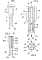
- an expansion fastener made in one piece from a suitable material, such as nylon, on which a cylindrical shaft 12, a lens-like head 14 and two are separated from one another by a relatively wide gap 18 Anchor sections 16 are to be distinguished.
- the expansion nail 10 is effectively reinforced by continuous glass fiber strands 26 laid in a U-shape inside. These glass fiber strands extend from the end of one anchor section into the head 14, are folded over there and end at the end of the other anchor section 16. Through these glass fiber strands 26, breaks in one or both anchor sections 16 are caused by driving the expanding nail into a building material such as gas concrete Avoided security.
- Each of the two anchor sections 16 is provided at its free end with an external cutting edge 20 which is delimited on the inside by a wedge surface 22 which runs obliquely inwards and upwards.
- the outer flank 24 of each anchor section 16 adjoining the cutting edge 20, on the other hand, runs smoothly and linearly up to the shaft shoulder.
- expansion anchors shown in FIGS. 2 to 4 of the drawing are completely driven into the building material so that their attachment end face 34 and 34a are aligned with the building material front surface.
- These expansion anchors 30 and 3oa are tubular and have a relatively narrow central bore 36 and 36a, into which, for example, a screw that fits is screwed, which can also be self-tapping and cuts its own thread into the central bore. Components to be fastened are then attached to the expansion anchor 30 or 30a with the aid of such an additional screw fixed.
- the expansion anchor 30 in FIGS. 2 and 3 has at the lower end of its essentially cylindrical shaft 32 a hollow cylindrical projection which is divided into four anchor sections 46, each with a ring segment-shaped cross section, by two axial slots perpendicular to one another.
- This expansion anchor 30 is also reinforced by continuous glass fiber strands 26, indicated by dash-dotted lines in FIG. 2, each extending from the end of one of the anchor sections 46 to the end face 34, folded there in a U-shape and being returned to the end of the opposite anchor section 46.
- the inner boundary of all anchor sections forms a foot bore 38 which runs concentrically to the central bore 36, and four gaps 48 remain due to the axial slot during the manufacture of the anchor sections 46.
- the partially cylindrical armature sections 46 in the end view have a partially cylindrical cutting edge 50 on their outer edge.
- the cutting edge 50 is connected to the surface of the foot bore 38 by a hollow conical surface 52.
- the outside of the shaft 32 is occupied by a total of four diametrically opposite wing sections 40, which have cutting edges 42 lying at the front in the driving-in direction and extending obliquely outwards and backwards.
- the expansion anchor 30 When the expansion anchor 30 is driven into a building material such as gas concrete, the cutting edges 50 and then the hollow cone surfaces 52 penetrate into it Building material. As a result, the glass fiber-reinforced anchor sections 46 are spread apart. The wing sections 40 then penetrate into the building material. The edges 42 on their front edges compress the adjacent building material. As a result, the expansion anchor 30 is held permanently and with the highest strength in the building material.
- a building material such as gas concrete
- the collar 54 gives the expansion anchor 30a an enlarged attachment end face 34 and defines its driving depth into the building material.
- This mounting hole 82 forms one at its bottom Truncated cone 84, which is complementary to the cutting edges 20 and 50 with wedge surface 22 and hollow cone surface 52 of the expansion fastener. As can be seen from FIG. 6, this truncated cone 84 optimally guides the anchor sections 16 (the same applies to the anchor sections 46), so that the expansion fastener is fixed in the building material with maximum holding force.
- a hole tool 60 or 60a according to FIG. 5 or 7 can advantageously be used to produce such mounting holes 82.
- Such punching tools are simply driven by hand into the relatively soft building material such as gas concrete, plasterboard or the like.
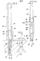
- FIG. 5 consists of a hollow handle 62 with an internal discharge channel 63 for cuttings and a lateral outlet opening 64 through which the cuttings can be removed.
- the front end of the hollow handle 62 in the working direction merges with an annular shoulder 66 into a thinner hollow mandrel 68 which is cylindrical throughout.
- the front end of the outer surface of the hollow mandrel 68 adjoins an annular cutting edge 70 which is delimited on the inside by a relatively short inner cone 72.
- Adjacent to the inner cone 72 is a short cylinder section 74 which, with an annular extension step 76 of only a few tenths of a millimeter, merges into the otherwise continuous and uniform inner diameter of the remaining hollow mandrel 68.
- the hollow mandrel 68 of the perforating tool 60 in FIG. 5 is relatively long and determines the maximum depth of an assembly hole 82 that can be produced (FIG. 6). If shorter mounting holes are required, as shown in FIG. 5, then spacer rings 80 are simply pushed onto the hollow mandrel 68, which stick thereon, for example, with a friction fit and, if necessary, can be removed or replaced by other rings. In operation, the punching tool 60 is pressed into the building material designated 58, such as gas concrete, gypsum or the like.
- the outer cylinder of the hollow mandrel 68 forms the outer wall of the mounting hole 82, and the material displaced by the inner cone 72 is compressed into a core, which crumbles into drill cuttings 78 when passing through the extension jump 76, which forms a tear-off edge, and the interior of the hollow mandrel in a loose arrangement 68 fills.
- the perforating tool 60 is pulled out of the mounting hole and the cuttings 78 are removed through the outlet opening 64.
- the desired truncated cone 84 remains on the base of the hole.
- the similar punch tool 60a shown in FIG. 7 differs essentially only in the grip area from the punch tool 60 described above. Details which are identical and bear the same reference numbers therefore do not need to be described again. This applies in particular to the hollow mandrel 68, which is only shorter in FIG. 7 than in FIG. 5.
- the hollow shaft 88 of the perforating tool 60a adjoining the shoulder 66 contains on the inside a discharge channel 63a for drill cuttings which is open at the top but can be closed by a push-on handle part 34.
- a recess 89 is machined into the upper end of the hollow shaft 88, and the relatively thin-walled tubular section of the hollow shaft in the region of this recess 89, which is left standing, is divided into crenellated wall sections by three slots 92 distributed over the circumference can be displaced to the outside within the material elasticity in order to then return to their original position.
Landscapes
- Engineering & Computer Science (AREA)
- General Engineering & Computer Science (AREA)
- Mechanical Engineering (AREA)
- Mining & Mineral Resources (AREA)
- Life Sciences & Earth Sciences (AREA)
- Geology (AREA)
- Fluid Mechanics (AREA)
- Environmental & Geological Engineering (AREA)
- Physics & Mathematics (AREA)
- General Life Sciences & Earth Sciences (AREA)
- Geochemistry & Mineralogy (AREA)
- Dowels (AREA)
- Joining Of Building Structures In Genera (AREA)
Applications Claiming Priority (2)
| Application Number | Priority Date | Filing Date | Title |
|---|---|---|---|
| DE2823372 | 1978-05-29 | ||
| DE19782823372 DE2823372A1 (de) | 1978-05-29 | 1978-05-29 | Spreizbefestiger sowie werkzeug und verfahren zum vorbereiten von loechern fuer solche befestiger |
Publications (1)
| Publication Number | Publication Date |
|---|---|
| EP0007980A1 true EP0007980A1 (fr) | 1980-02-20 |
Family
ID=6040443
Family Applications (1)
| Application Number | Title | Priority Date | Filing Date |
|---|---|---|---|
| EP79101616A Withdrawn EP0007980A1 (fr) | 1978-05-29 | 1979-05-28 | Organe de fixation à tige s'évasant, outil et procédé de préparation des trous pour de tels organes de fixation |
Country Status (2)
| Country | Link |
|---|---|
| EP (1) | EP0007980A1 (fr) |
| DE (1) | DE2823372A1 (fr) |
Cited By (4)
| Publication number | Priority date | Publication date | Assignee | Title |
|---|---|---|---|---|
| GB2132824A (en) * | 1982-12-24 | 1984-07-11 | Daniel James Cherrington | Electric fence insulator |
| JPS63132109U (fr) * | 1987-02-20 | 1988-08-30 | ||
| GB2259344A (en) * | 1991-09-03 | 1993-03-10 | Michael Kenny | Fixing devices for blockwork |
| DE4138955C1 (fr) * | 1991-11-27 | 1993-04-29 | Tadeusz 6000 Frankfurt De Tumalski |
Families Citing this family (3)
| Publication number | Priority date | Publication date | Assignee | Title |
|---|---|---|---|---|
| EP0145886B1 (fr) * | 1983-12-15 | 1987-08-26 | Fischerwerke Arthur Fischer GmbH & Co. KG | Clou à expansion |
| DE4406953A1 (de) * | 1994-03-03 | 1995-09-07 | Fischer Artur Werke Gmbh | Durch Einschlagen verankerbares Befestigungselement |
| JPH11108024A (ja) * | 1997-10-07 | 1999-04-20 | Wakai Sangyo Kk | 建材の移動方法 |
Citations (8)
| Publication number | Priority date | Publication date | Assignee | Title |
|---|---|---|---|---|
| DE1887C (de) * | J. E. Bennett in Sheffield | Einrichtungen an Nägeln und Bolzen | ||
| FR790800A (fr) * | 1935-06-03 | 1935-11-27 | Clou à ancrage | |
| US2510693A (en) * | 1944-03-29 | 1950-06-06 | Lee B Green | Fastening member |
| GB718669A (en) * | 1952-09-19 | 1954-11-17 | Vickers Electrical Co Ltd | Improvements relating to a method of and apparatus for testing non-magnetic material |
| FR1267864A (fr) * | 1960-06-13 | 1961-07-28 | Cheville pour la fixation de vis, clous et analogues | |
| FR1305102A (fr) * | 1961-11-08 | 1962-09-28 | Cheville en matière synthétique | |
| DE1400218A1 (de) * | 1961-01-04 | 1968-10-17 | Moeller Geb Maag Dr Irmgard | Duebel und Verfahren zum Befestigen desselben |
| FR2092471A5 (fr) * | 1970-04-21 | 1972-01-21 | Tuflex Ag |
-
1978
- 1978-05-29 DE DE19782823372 patent/DE2823372A1/de not_active Withdrawn
-
1979
- 1979-05-28 EP EP79101616A patent/EP0007980A1/fr not_active Withdrawn
Patent Citations (8)
| Publication number | Priority date | Publication date | Assignee | Title |
|---|---|---|---|---|
| DE1887C (de) * | J. E. Bennett in Sheffield | Einrichtungen an Nägeln und Bolzen | ||
| FR790800A (fr) * | 1935-06-03 | 1935-11-27 | Clou à ancrage | |
| US2510693A (en) * | 1944-03-29 | 1950-06-06 | Lee B Green | Fastening member |
| GB718669A (en) * | 1952-09-19 | 1954-11-17 | Vickers Electrical Co Ltd | Improvements relating to a method of and apparatus for testing non-magnetic material |
| FR1267864A (fr) * | 1960-06-13 | 1961-07-28 | Cheville pour la fixation de vis, clous et analogues | |
| DE1400218A1 (de) * | 1961-01-04 | 1968-10-17 | Moeller Geb Maag Dr Irmgard | Duebel und Verfahren zum Befestigen desselben |
| FR1305102A (fr) * | 1961-11-08 | 1962-09-28 | Cheville en matière synthétique | |
| FR2092471A5 (fr) * | 1970-04-21 | 1972-01-21 | Tuflex Ag |
Cited By (5)
| Publication number | Priority date | Publication date | Assignee | Title |
|---|---|---|---|---|
| GB2132824A (en) * | 1982-12-24 | 1984-07-11 | Daniel James Cherrington | Electric fence insulator |
| JPS63132109U (fr) * | 1987-02-20 | 1988-08-30 | ||
| GB2259344A (en) * | 1991-09-03 | 1993-03-10 | Michael Kenny | Fixing devices for blockwork |
| GB2259344B (en) * | 1991-09-03 | 1995-03-01 | Michael Kenny | Fixing devices |
| DE4138955C1 (fr) * | 1991-11-27 | 1993-04-29 | Tadeusz 6000 Frankfurt De Tumalski |
Also Published As
| Publication number | Publication date |
|---|---|
| DE2823372A1 (de) | 1979-12-06 |
Similar Documents
| Publication | Publication Date | Title |
|---|---|---|
| DE69301369T2 (de) | Betonanker | |
| DE2656628A1 (de) | Nagelstreifen fuer nagelmaschinen | |
| EP0870561B1 (fr) | Outil de forage | |
| EP2191152B1 (fr) | Utilisation d'un rivet aveugle et procédé de placement d'un rivet aveugle | |
| DE3535618A1 (de) | Schwerlastanker mit spreizhuelse | |
| DE3833040A1 (de) | Bohrhilfevorrichtung | |
| DE102018119075A1 (de) | Spreizanker | |
| DE69515505T2 (de) | Verbesserung an einer mauerankervorrichtung | |
| DE3321623C2 (de) | Isolierplattendübel aus Kunststoff | |
| DE2823372A1 (de) | Spreizbefestiger sowie werkzeug und verfahren zum vorbereiten von loechern fuer solche befestiger | |
| EP0808696B1 (fr) | Système de fixation et procédé de réalisation de fixations | |
| EP0363313A2 (fr) | Foret à couronne à pierre | |
| EP0351493B1 (fr) | Foret pour la pierre | |
| DE1289366B (de) | Spreizbare Verankerung zum Einsatz in ein in Beton, Mauerwerk od. dgl. angebrachtes Bohrloch | |
| EP0724085A1 (fr) | Ancre de fixation à contre-dépouille avec engagement de forme | |
| DE19607446A1 (de) | Schlagdübel | |
| EP0262444B1 (fr) | Dispositif d'ancrage, notamment cheville | |
| DE8806973U1 (de) | Fräswerkzeug | |
| EP0245865B1 (fr) | Procédé de pose d'une goupille d'ancrage dans un trou foré d'un support et goupille d'ancrage à utiliser avec ce procédé | |
| DE3530296A1 (de) | Vorrichtung zum herstellen von wandausnehmungen | |
| EP0750082B1 (fr) | Dispositif d'ancrage d'éléments de construction entre une surface | |
| DE3909481A1 (de) | Bohrwerkzeug | |
| DE19627272C2 (de) | Dübel | |
| EP0641417A1 (fr) | Ancre posable par battage. | |
| EP2466158A1 (fr) | Procédé de fixation de chevilles métalliques pourvues de fentes multiples et d'un filetage intérieur |
Legal Events
| Date | Code | Title | Description |
|---|---|---|---|
| PUAI | Public reference made under article 153(3) epc to a published international application that has entered the european phase |
Free format text: ORIGINAL CODE: 0009012 |
|
| AK | Designated contracting states |
Designated state(s): AT BE CH FR GB IT LU NL SE |
|
| STAA | Information on the status of an ep patent application or granted ep patent |
Free format text: STATUS: THE APPLICATION IS DEEMED TO BE WITHDRAWN |
|
| 18D | Application deemed to be withdrawn |
Effective date: 19801116 |