EP0008004A1 - Appareil d'éclairage à réflecteur amovible - Google Patents
Appareil d'éclairage à réflecteur amovible Download PDFInfo
- Publication number
- EP0008004A1 EP0008004A1 EP79102353A EP79102353A EP0008004A1 EP 0008004 A1 EP0008004 A1 EP 0008004A1 EP 79102353 A EP79102353 A EP 79102353A EP 79102353 A EP79102353 A EP 79102353A EP 0008004 A1 EP0008004 A1 EP 0008004A1
- Authority
- EP
- European Patent Office
- Prior art keywords
- housing
- side mirrors
- mirror
- insert
- lamp
- Prior art date
- Legal status (The legal status is an assumption and is not a legal conclusion. Google has not performed a legal analysis and makes no representation as to the accuracy of the status listed.)
- Granted
Links
- BULVZWIRKLYCBC-UHFFFAOYSA-N phorate Chemical group CCOP(=S)(OCC)SCSCC BULVZWIRKLYCBC-UHFFFAOYSA-N 0.000 claims 1
- 239000000969 carrier Substances 0.000 abstract 2
- 241000446313 Lamella Species 0.000 description 2
- 238000007664 blowing Methods 0.000 description 1
- 238000010276 construction Methods 0.000 description 1
- 230000004313 glare Effects 0.000 description 1
Images

Classifications
-
- F—MECHANICAL ENGINEERING; LIGHTING; HEATING; WEAPONS; BLASTING
- F21—LIGHTING
- F21S—NON-PORTABLE LIGHTING DEVICES; SYSTEMS THEREOF; VEHICLE LIGHTING DEVICES SPECIALLY ADAPTED FOR VEHICLE EXTERIORS
- F21S8/00—Lighting devices intended for fixed installation
- F21S8/04—Lighting devices intended for fixed installation intended only for mounting on a ceiling or the like overhead structures
-
- F—MECHANICAL ENGINEERING; LIGHTING; HEATING; WEAPONS; BLASTING
- F21—LIGHTING
- F21V—FUNCTIONAL FEATURES OR DETAILS OF LIGHTING DEVICES OR SYSTEMS THEREOF; STRUCTURAL COMBINATIONS OF LIGHTING DEVICES WITH OTHER ARTICLES, NOT OTHERWISE PROVIDED FOR
- F21V17/00—Fastening of component parts of lighting devices, e.g. shades, globes, refractors, reflectors, filters, screens, grids or protective cages
- F21V17/10—Fastening of component parts of lighting devices, e.g. shades, globes, refractors, reflectors, filters, screens, grids or protective cages characterised by specific fastening means or way of fastening
- F21V17/16—Fastening of component parts of lighting devices, e.g. shades, globes, refractors, reflectors, filters, screens, grids or protective cages characterised by specific fastening means or way of fastening by deformation of parts; Snap action mounting
- F21V17/164—Fastening of component parts of lighting devices, e.g. shades, globes, refractors, reflectors, filters, screens, grids or protective cages characterised by specific fastening means or way of fastening by deformation of parts; Snap action mounting the parts being subjected to bending, e.g. snap joints
-
- F—MECHANICAL ENGINEERING; LIGHTING; HEATING; WEAPONS; BLASTING
- F21—LIGHTING
- F21Y—INDEXING SCHEME ASSOCIATED WITH SUBCLASSES F21K, F21L, F21S and F21V, RELATING TO THE FORM OR THE KIND OF THE LIGHT SOURCES OR OF THE COLOUR OF THE LIGHT EMITTED
- F21Y2103/00—Elongate light sources, e.g. fluorescent tubes
Definitions
- the invention relates to a luminaire for a rod-shaped fluorescent lamp with a housing and a gutter-shaped mirror system arranged therein, which consists of a roof mirror attached above the lamp and two side mirrors, the side mirrors with cross blades connecting them forming an insert which is detachably held in the housing.
- such a lamp known for example from DE-GM 1 971 019, required a relatively high outlay for the construction and mounting of the mirror insert and of the roof mirror.
- the use was generally given a high degree of inherent rigidity through the use of high-reaching transverse slats and profiled frames; four detachable connections were required for mounting in the housing.
- the invention has for its object to reduce the design effort for a lamp of the type mentioned; in particular, the use of a Mirror use with less inherent rigidity may be possible.
- the inventive solution to this problem is characterized in a lamp of the type mentioned by at least two fixed to the bottom of the housing, transverse to the longitudinal axis of the housing support for holding the roof mirror, each having two stop surfaces for the edge strips of the side mirror, through which the only at its front ends, the insert is guided centrally in the housing.
- the invention manages with a mirror insert with very little inherent rigidity. It enables the use of very thin material and no stiffening frames. It is sufficient to connect the two side mirrors to one another only by means of the transverse slats, which in turn only need to be 1/4 to 1/3 of the height of the side mirrors; this in turn benefits the efficiency of the luminaire, since high cross slats lead to unnecessary multiple reflections.
- the stop surfaces in the carrier and the edge strips of the side mirrors interacting therewith can run vertically or - as in the exemplary embodiment - horizontally. In any case, tilting of the mirror insert around the two front bearing points is avoided and proper alignment within the housing is guaranteed.
- the front mounting of the mirror insert has the additional advantage that it is still usable if storage of the mirror insert on the long sides of the housing is no longer usable because of the height of the mirror insert compared to the light exit opening.
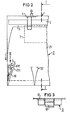
- the housing 1 which is rectangular in cross section (FIG. 1) and in longitudinal section (FIG. 2) has a flat bottom 11, flat end walls 12 and a light exit opening 13;
- a mirror insert 2 which consists of two parabolically curved side mirrors 21 and V-shaped transverse slats 22 connecting them to one another.
- the position of the lamp 7 is indicated by dashed lines in the figures.
- the cross blades 22 do not extend higher than is necessary in view of a sufficient glare limitation; the section of the side mirrors extending above the transverse slats is accordingly more than twice as long as the height of the transverse slats. If a thin mirror material (0.2 mm) is used and there is no additional frame for the mirror insert 2 in the light exit opening, this results in a very low inherent rigidity of the mirror insert.
- At least two supports 4 are therefore provided, which are fastened at a distance from one another on the bottom 11 of the housing 1.
- These are plastic molded parts which have hook-shaped feet 45 on their back have, which reach resiliently through recesses in the bottom 11, so that the carrier can be attached by simply blowing it in.
- These supports 4, which run transversely to the longitudinal axis of the housing, each have at their two outer ends a horizontally extending stop surface 41 against which an angled edge strip 211 of each side mirror 21 rests when the mirror insert 2 is inserted into the housing 1. The dimensions are so matched to one another that when the edge strips 211 bear against the stop surfaces 41, the mirror insert 2 is aligned with respect to the light exit opening 13.
- each closure 6 is sufficient, which is attached centrally to the inside of each end wall 12 of the housing.
- Each closure 6 consists of a ferler arm 61 with a shoulder 611 (FIG. 2) on which the angled edge of the last, halved transverse lamella 221 is supported.
- the closures 6 are practically completely covered by the halved transverse slats 221.
- the spring arm 61 is pressed against the end wall 12, whereby the angled edge of the last lamella 221 is released. Tilting of the mirror insert 2 around the shoulder 611 of the closures 6 is prevented by the carrier 4 with its stop surfaces 41.
- the front mounting of the mirror insert 2 means a pivoting movement about a transverse axis of the mirror insert when removing it from the housing. Such a pivoting movement is still possible even with a very high height of the mirror insert and a narrow width of the light exit opening 13 if the otherwise usual mounting of the mirror insert along a longitudinal edge of the housing can no longer be carried out.
- the carrier 4 also serve to hold the roof spike gel 3 and for this purpose have webs 43, 44 and support surfaces 42.
- Support surfaces 42 and webs 43, 44 are adapted to the rocker-shaped contour of the roof mirror 3 so that, after being inserted under prestress, these webs bear against these webs on the one hand and with an edge strip 311 on the support surfaces 42 on the other.
- the support surfaces 42 for the edge strips 311 of the roof mirror 3 are arranged opposite the ash surfaces 41 for the edge strips 211 of the side mirrors 21 such that a gap 5 remains free between the side mirrors 21 and the roof mirror 3; this enables the luminaire to be used in conjunction with a housing with at least one corresponding opening for exhaust air discharge, also as an exhaust air luminaire.
- the side mirrors and the roof mirror can also be designed asymmetrically, in deviation from the example shown.
Landscapes
- Engineering & Computer Science (AREA)
- General Engineering & Computer Science (AREA)
- Mirrors, Picture Frames, Photograph Stands, And Related Fastening Devices (AREA)
- Non-Portable Lighting Devices Or Systems Thereof (AREA)
- Optical Elements Other Than Lenses (AREA)
- Securing Globes, Refractors, Reflectors Or The Like (AREA)
Priority Applications (1)
| Application Number | Priority Date | Filing Date | Title |
|---|---|---|---|
| AT79102353T ATE234T1 (de) | 1978-08-02 | 1979-07-09 | Leuchte mit herausnehmbarem spiegeleinsatz. |
Applications Claiming Priority (2)
| Application Number | Priority Date | Filing Date | Title |
|---|---|---|---|
| DE2833894A DE2833894C2 (de) | 1978-08-02 | 1978-08-02 | Leuchte für eine stabförmige Leuchtstofflampe |
| DE2833894 | 1978-08-02 |
Publications (2)
| Publication Number | Publication Date |
|---|---|
| EP0008004A1 true EP0008004A1 (fr) | 1980-02-20 |
| EP0008004B1 EP0008004B1 (fr) | 1981-09-16 |
Family
ID=6046034
Family Applications (1)
| Application Number | Title | Priority Date | Filing Date |
|---|---|---|---|
| EP79102353A Expired EP0008004B1 (fr) | 1978-08-02 | 1979-07-09 | Appareil d'éclairage à réflecteur amovible |
Country Status (3)
| Country | Link |
|---|---|
| EP (1) | EP0008004B1 (fr) |
| AT (1) | ATE234T1 (fr) |
| DE (1) | DE2833894C2 (fr) |
Cited By (7)
| Publication number | Priority date | Publication date | Assignee | Title |
|---|---|---|---|---|
| EP0199203A3 (en) * | 1985-04-16 | 1988-09-21 | Siemens Aktiengesellschaft Berlin Und Munchen | Lamp with an elongated hollow reflector |
| US4841421A (en) * | 1988-01-15 | 1989-06-20 | Siemens Aktiengesellschaft | Housing for long-field lamps having interchangeable louver insert |
| EP0435394A1 (fr) * | 1989-12-27 | 1991-07-03 | Koninklijke Philips Electronics N.V. | Appareil d'éclairage |
| EP0467056A3 (en) * | 1990-07-14 | 1992-04-08 | Zumtobel Aktiengesellschaft | Trough-shaped reflector for lamps |
| DE29613948U1 (de) * | 1996-08-12 | 1997-12-11 | Zumtobel Licht Gmbh, Dornbirn | Leuchte mit mindestens einer Lampe, einem Reflektor und einem Rasterreflektor |
| GB2315850A (en) * | 1996-08-02 | 1998-02-11 | Spectral Technology Limited | Elongate lamp for curing coatings |
| WO2000017571A1 (fr) * | 1998-09-17 | 2000-03-30 | Koninklijke Philips Electronics N.V. | Luminaire |
Families Citing this family (1)
| Publication number | Priority date | Publication date | Assignee | Title |
|---|---|---|---|---|
| DE3138567A1 (de) * | 1981-09-28 | 1983-04-21 | Siemens AG, 1000 Berlin und 8000 München | Anordnung zur aufhellung der deckenumgebung einer nach unten strahlenden leuchte |
Citations (4)
| Publication number | Priority date | Publication date | Assignee | Title |
|---|---|---|---|---|
| GB914526A (en) * | 1959-05-11 | 1963-01-02 | William Alfred Trott | Luminaires |
| CH373814A (fr) * | 1961-04-14 | 1963-12-15 | Rubeli Jean | Installation d'éclairage |
| CH521550A (de) * | 1971-01-20 | 1972-04-15 | Novelectric Ag | Gehäuseteil mit lösbar befestigtem elektrischem Einsatz |
| FR2335138A7 (fr) * | 1975-12-12 | 1977-07-08 | Semperlux Gmbh | Luminaire a profiles reflechissants, notamment pour des plafonds comportant un reseau determine |
-
1978
- 1978-08-02 DE DE2833894A patent/DE2833894C2/de not_active Expired
-
1979
- 1979-07-09 EP EP79102353A patent/EP0008004B1/fr not_active Expired
- 1979-07-09 AT AT79102353T patent/ATE234T1/de not_active IP Right Cessation
Patent Citations (4)
| Publication number | Priority date | Publication date | Assignee | Title |
|---|---|---|---|---|
| GB914526A (en) * | 1959-05-11 | 1963-01-02 | William Alfred Trott | Luminaires |
| CH373814A (fr) * | 1961-04-14 | 1963-12-15 | Rubeli Jean | Installation d'éclairage |
| CH521550A (de) * | 1971-01-20 | 1972-04-15 | Novelectric Ag | Gehäuseteil mit lösbar befestigtem elektrischem Einsatz |
| FR2335138A7 (fr) * | 1975-12-12 | 1977-07-08 | Semperlux Gmbh | Luminaire a profiles reflechissants, notamment pour des plafonds comportant un reseau determine |
Cited By (10)
| Publication number | Priority date | Publication date | Assignee | Title |
|---|---|---|---|---|
| EP0199203A3 (en) * | 1985-04-16 | 1988-09-21 | Siemens Aktiengesellschaft Berlin Und Munchen | Lamp with an elongated hollow reflector |
| US4841421A (en) * | 1988-01-15 | 1989-06-20 | Siemens Aktiengesellschaft | Housing for long-field lamps having interchangeable louver insert |
| EP0435394A1 (fr) * | 1989-12-27 | 1991-07-03 | Koninklijke Philips Electronics N.V. | Appareil d'éclairage |
| EP0467056A3 (en) * | 1990-07-14 | 1992-04-08 | Zumtobel Aktiengesellschaft | Trough-shaped reflector for lamps |
| GB2315850A (en) * | 1996-08-02 | 1998-02-11 | Spectral Technology Limited | Elongate lamp for curing coatings |
| US5973331A (en) * | 1996-08-02 | 1999-10-26 | Nordson Corporation | Lamp assembly |
| GB2315850B (en) * | 1996-08-02 | 2000-10-04 | Spectral Technology Limited | Lamp assembly |
| DE29613948U1 (de) * | 1996-08-12 | 1997-12-11 | Zumtobel Licht Gmbh, Dornbirn | Leuchte mit mindestens einer Lampe, einem Reflektor und einem Rasterreflektor |
| WO2000017571A1 (fr) * | 1998-09-17 | 2000-03-30 | Koninklijke Philips Electronics N.V. | Luminaire |
| JP2002525816A (ja) * | 1998-09-17 | 2002-08-13 | コーニンクレッカ フィリップス エレクトロニクス エヌ ヴィ | 照明器具 |
Also Published As
| Publication number | Publication date |
|---|---|
| DE2833894B1 (de) | 1979-11-08 |
| ATE234T1 (de) | 1981-10-15 |
| DE2833894C2 (de) | 1980-07-31 |
| EP0008004B1 (fr) | 1981-09-16 |
Similar Documents
| Publication | Publication Date | Title |
|---|---|---|
| EP0860654B1 (fr) | Armature allongée pour bandes lumineuses | |
| WO1997044616A1 (fr) | Systeme d'eclairage muni d'un corps de base servant de support pour au moins une lampe | |
| EP0574761B1 (fr) | Boîtier à vasque d'une armature lumineuse avec panier réfléchissant | |
| DE19635906A1 (de) | Beleuchtungshalterung mit einem parabolischen Gitter | |
| EP0008004B1 (fr) | Appareil d'éclairage à réflecteur amovible | |
| EP0359069A2 (fr) | Procédé de fabrication d'un paralume | |
| EP0116909A1 (fr) | Fixation de couvercle rabattable pour armature lumineuse | |
| EP0140058A1 (fr) | Support pour appareil d'éclairage encastré | |
| EP0453956A2 (fr) | Dispositif d'éclairage à faisceau asymétrique | |
| EP2994693A1 (fr) | Élément de recouvrement pour luminaire surfacique | |
| EP0952390A2 (fr) | Chemin lumineux | |
| DE2758261C3 (de) | Leuchtenraster | |
| DE3300337C2 (de) | Vorrichtung zum Haltern eines langgestreckten Leuchtenunterteils an einem langgestreckten Leuchtenoberteil | |
| DE2054470A1 (de) | Beleuchtungskonstruktion | |
| DE9013738U1 (de) | Leuchtkasten | |
| DE9300210U1 (de) | Lichtband-Tragschiene | |
| DE1238863B (de) | Leuchte fuer langgestreckte Lichtquellen | |
| DE2505562A1 (de) | Vorrichtung zur befestigung einer deckeneinbauleuchte | |
| EP0017824A1 (fr) | Luminaire de forme allongée | |
| EP0957308B1 (fr) | Feu pour véhicule | |
| EP0148335A2 (fr) | Armature lumineuse pour lampe de forme allongée | |
| DE3334803A1 (de) | Halterung einer absenkbaren leuchtenabdeckung | |
| DE20108425U1 (de) | Beleuchtungseinheit mit einstellbarem Lichtkegel | |
| EP1036705A2 (fr) | Feux de véhicule | |
| DE1915202U (de) | Montageanordnung fuer lampenreihen. |
Legal Events
| Date | Code | Title | Description |
|---|---|---|---|
| PUAI | Public reference made under article 153(3) epc to a published international application that has entered the european phase |
Free format text: ORIGINAL CODE: 0009012 |
|
| AK | Designated contracting states |
Designated state(s): AT CH IT SE |
|
| 17P | Request for examination filed | ||
| ITF | It: translation for a ep patent filed | ||
| GRAA | (expected) grant |
Free format text: ORIGINAL CODE: 0009210 |
|
| AK | Designated contracting states |
Designated state(s): AT CH IT SE |
|
| REF | Corresponds to: |
Ref document number: 234 Country of ref document: AT Date of ref document: 19811015 Kind code of ref document: T |
|
| PGFP | Annual fee paid to national office [announced via postgrant information from national office to epo] |
Ref country code: SE Payment date: 19840630 Year of fee payment: 6 |
|
| PG25 | Lapsed in a contracting state [announced via postgrant information from national office to epo] |
Ref country code: SE Effective date: 19850710 |
|
| PGFP | Annual fee paid to national office [announced via postgrant information from national office to epo] |
Ref country code: AT Payment date: 19890630 Year of fee payment: 11 |
|
| PGFP | Annual fee paid to national office [announced via postgrant information from national office to epo] |
Ref country code: CH Payment date: 19891024 Year of fee payment: 11 |
|
| PG25 | Lapsed in a contracting state [announced via postgrant information from national office to epo] |
Ref country code: AT Effective date: 19900709 |
|
| PG25 | Lapsed in a contracting state [announced via postgrant information from national office to epo] |
Ref country code: CH Effective date: 19900731 |
|
| REG | Reference to a national code |
Ref country code: CH Ref legal event code: PL |
|
| EUG | Se: european patent has lapsed |
Ref document number: 79102353.4 Effective date: 19860730 |
|
| PLBE | No opposition filed within time limit |
Free format text: ORIGINAL CODE: 0009261 |
|
| STAA | Information on the status of an ep patent application or granted ep patent |
Free format text: STATUS: NO OPPOSITION FILED WITHIN TIME LIMIT |