EP0148335A2 - Armature lumineuse pour lampe de forme allongée - Google Patents
Armature lumineuse pour lampe de forme allongée Download PDFInfo
- Publication number
- EP0148335A2 EP0148335A2 EP84112317A EP84112317A EP0148335A2 EP 0148335 A2 EP0148335 A2 EP 0148335A2 EP 84112317 A EP84112317 A EP 84112317A EP 84112317 A EP84112317 A EP 84112317A EP 0148335 A2 EP0148335 A2 EP 0148335A2
- Authority
- EP
- European Patent Office
- Prior art keywords
- insert
- spring
- frame
- bearing part
- piece
- Prior art date
- Legal status (The legal status is an assumption and is not a legal conclusion. Google has not performed a legal analysis and makes no representation as to the accuracy of the status listed.)
- Granted
Links
Images


Classifications
-
- F—MECHANICAL ENGINEERING; LIGHTING; HEATING; WEAPONS; BLASTING
- F21—LIGHTING
- F21V—FUNCTIONAL FEATURES OR DETAILS OF LIGHTING DEVICES OR SYSTEMS THEREOF; STRUCTURAL COMBINATIONS OF LIGHTING DEVICES WITH OTHER ARTICLES, NOT OTHERWISE PROVIDED FOR
- F21V17/00—Fastening of component parts of lighting devices, e.g. shades, globes, refractors, reflectors, filters, screens, grids or protective cages
- F21V17/10—Fastening of component parts of lighting devices, e.g. shades, globes, refractors, reflectors, filters, screens, grids or protective cages characterised by specific fastening means or way of fastening
- F21V17/16—Fastening of component parts of lighting devices, e.g. shades, globes, refractors, reflectors, filters, screens, grids or protective cages characterised by specific fastening means or way of fastening by deformation of parts; Snap action mounting
- F21V17/164—Fastening of component parts of lighting devices, e.g. shades, globes, refractors, reflectors, filters, screens, grids or protective cages characterised by specific fastening means or way of fastening by deformation of parts; Snap action mounting the parts being subjected to bending, e.g. snap joints
Definitions
- the invention relates to a lamp for a rod-shaped lamp with a frame in which an insert, in particular a reflector insert according to the preamble of claim 1, is detachably mounted.
- a locking part which is attached to a transverse wall of the lamp housing and has a resilient support arm on which the last transverse lamella of the reflector insert is supported; this support arm can be pressed against a spring force into an open position by means of a handle which slightly projects above the last transverse lamella.
- the invention has for its object to design the releasable holder of the insert so that it is useful even with a larger, covered by an end piece of the insert accessory space between the light outlet opening and the lamp frame, especially when there is an additional requirement that this accessory space when removed Use should be freely accessible.
- the carrying device is connected to the insert which can be removed from the frame, the frame itself serves only as a support; it therefore does not need to have a specific shape and / or special built-in parts.
- the invention makes it possible to accommodate lighting components, such as sockets, fastening devices, cables, in the accessory room in such a way that these parts are freely accessible when the insert is removed. This is particularly important if, due to the very low overall height of the frame, there is no space for these parts elsewhere.
- the locking part can be arranged rotatably or displaceably between the two supporting walls of the bearing part, in which case the handle can be accessible from the lamp space and / or through a recess in the end piece.
- the locking part together with the handle and spring is preferably designed as a one-piece plastic part.
- the bearing part of the carrying device and the end piece of the insert are designed as a one-piece plastic part.
- the bearing part can also be mechanically connected to the end piece of the insert, for example inserted through a recess in the end piece and locked in this position.
- a cross piece of the locking part is preferably used as the locking means.
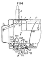
- Both exemplary embodiments are based on a lamp with a rectangular lamp frame with longitudinal walls 21 and transverse walls 22, which delimit an upper and a lower light outlet opening.
- the cut transverse wall 22 shows the identical profile of these walls.
- a support member 3 which is connected to a pendulum 31 for hanging the lamp; the supporting part 3 also has a holder 32 with a holder 4 for a rod-shaped lamp 1. The introduction of a feed line 5 by the pendulum 31 is also shown.
- the lamp 1 is assigned a channel-shaped reflector insert 6 with longitudinal reflector walls 61, which pa on both sides of the lamp run parallel to her; between these longitudinal reflector walls are arranged a plurality of - not shown - transverse slats.
- the optically effective part of the reflector insert 6 ends with an end wall 60 at such a distance in front of the transverse wall 22 of the frame that an accessory space 20 with the already mentioned accessories - socket 4 and the like - is separated. This is covered in the plane of the lower light exit opening by the bottom 701 of a carrying device 7, which is part of the reflector insert 6 and consists of a bearing part 70 and a blocking part 71 rotatably mounted therein.
- the bearing part 70 - a molded part made of plastic - extends between the two longitudinal reflector walls 61 and is connected to them by longitudinal walls 703, which have the same outer contour as these longitudinal reflector walls.
- the longitudinal walls 703 are connected to one another by a transverse wall 702, which has the shape of a transverse lamella and against which the end wall 60 rests, but which can also be designed to be reflective.
- two supporting walls 705 are arranged between the longitudinal walls 703 at a distance from one another and parallel to the longitudinal axis L of the lamp, which have mutually opposite guide grooves 7051, in which a slide 711 is arranged to be displaceable in the direction of the longitudinal axis L. is.
- the two supporting walls 705 have two pivot bearings 7052 located opposite one another approximately in the middle between the guide grooves and the base 701, in which a two-armed rotary lever 712 with pin 7121 is rotatably arranged about an axis of rotation 700 running parallel to the base 701.
- the pivot bearings are located in a sufficiently elastic edge area of the supporting walls so that they can be elastically pushed apart for the insertion of the rotary lever 712 and spring back again.
- the rotary lever 712 is connected at one end to a support arm 713, which is supported on an inner edge 220 of the transverse wall 22 of the frame and is held in the end position shown by a spring 714 with the two spring arms 7141, 7142, which are in contact with the free spring arm 7142 is supported against a stop part 7022 of the bearing piece 70.
- the other end of the rotary lever 712 is connected via a thinned area of sufficient elasticity to one end of the slide 711, which has a handle 7111 at its other end, which projects somewhat into the lamp space through a cutout 7021 in the transverse wall 702.
- the rotary lever 712 forms together with the support arm 713, spring 714, slide 711 and handle 7111 a one-piece locking part 71 made of plastic.
- the entire light exit opening enclosed by the transverse and longitudinal walls of the frame is closed off by the reflector insert 6.
- a reflector insert To insert such a reflector insert into the frame, it is inserted with one end into the frame, specifically with a support arm also present there, and then pivoted into the frame, the support arm 713 starting with a wedge-shaped thrust piece 710 against the edge of the frame and is pressed back against the force of the spring 714 until - with the reflector insert fully swung in - it springs out behind the inner edge 220 of the transverse wall 22 into the position shown in FIG. 1 and carries the reflector insert.
- the support arm 713 then moves counter to the force of the spring 714 to the right until the reflector insert 6 can be pulled out downwards.
- the insert 6.1 has an end piece 62.1 made of metal, which is preferably in one piece with the angled end wall 60.1.
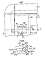
- a recess 620.1 is provided, into which a bearing part 70.1 is inserted from below, which overlaps the edges of the recess with a supporting edge 707.1.
- the bearing part 70.1 has two supporting walls 705.1, 706.1 running parallel to one another and to the longitudinal axis L and transverse walls 702.11, 702.12 running at a right angle thereto and having a lower height; these walls enclose an opening 7070.1 through which the handle 7111.1 of a locking part 71.1 is accessible.
- the locking part 71.1 is essentially a slide 711.1, which is mounted in a longitudinally displaceable manner via guide prisms 7112.1 in associated guide grooves 7051.1, 7061.1 of the supporting walls 705.1, 706.1.
- the slide 711.1 has at one end a support arm 713.1, which - in the blocking position shown in FIG. 3 - is supported on the inner edge 220 of the transverse wall 22 of the frame 2.
- the slide 711.1 also has two V-shaped partial springs 714.11, 714.12, which are arranged on both sides of the slide 711.1 and together with the slide form an integral plastic part.
- the end of the one spring arm 7141.11, 7141.12 of the two partial springs 714.11, 714.12 is connected to the slide 711.1 in the region of the support arm 713.1; these spring arms are equipped with wedge-shaped thrust pieces 710.1 (FIG 3, 5).
- the ends of the other spring arms 7142.11, 7142.12 of both partial springs pass into an angled end piece 7142.111, 7142.121; these end pieces are then connected to one another by a cross piece of 7143.1, as can be seen particularly clearly in FIG. 5, which shows a top view of the locking part 71.1 with the partial springs relaxed.
- the crosspiece 7143.1 is supported against the transverse wall 702.11 designed as a stop part 7022.1, this transverse wall engaging over the crosspiece 7143.1 with a holding leg 7023.1 - FIGS. 3 and 6: on the one hand, the spring with its partial springs 714.11, 714.12 is preloaded and presses the slide 711.1 in the blocked position shown in FIG 3. Furthermore, the dimensions - particularly evident from FIGS.
- bearing part 70.1 is also held in the recess 620.1 of the end piece 62.1: namely, on the one hand, the support rim 707.1 lies on the outside of the end piece 62.1 and overlaps on the other hand, with the holding leg 7023.1, the cross piece 7143.1, which rests on the inside of the end piece 62.1.
- An additional holder is caused by a spacer 7113.1, which is formed on the underside of the slide 711.1 - FIG 3 - and is dimensioned such that the supporting edge 707.1 via the supporting wall 705.1 and the slide 711.1 guided therein into the one shown in FIGS. 3, 4, 6 Stop position is pressed.
- this counter bearing 7053.1 is the end wall of each support wall 705.1, 706.1.
- a separate trough-shaped reflector insert with an associated carrying device can be provided for each lamp; the individual trough-shaped reflectors can, however, also be combined to form a one-piece reflector and supported on each end face by a carrying device of the type described.
Landscapes
- Engineering & Computer Science (AREA)
- General Engineering & Computer Science (AREA)
- Endoscopes (AREA)
- Cold Air Circulating Systems And Constructional Details In Refrigerators (AREA)
- Fastening Of Light Sources Or Lamp Holders (AREA)
- Securing Globes, Refractors, Reflectors Or The Like (AREA)
- Non-Portable Lighting Devices Or Systems Thereof (AREA)
- Vessels And Coating Films For Discharge Lamps (AREA)
- Circuit Arrangement For Electric Light Sources In General (AREA)
- Connecting Device With Holders (AREA)
- Lighters Containing Fuel (AREA)
- Lasers (AREA)
Priority Applications (1)
| Application Number | Priority Date | Filing Date | Title |
|---|---|---|---|
| AT84112317T ATE49463T1 (de) | 1983-12-23 | 1984-10-12 | Leuchte fuer eine stabfoermige lampe. |
Applications Claiming Priority (2)
| Application Number | Priority Date | Filing Date | Title |
|---|---|---|---|
| DE3346788 | 1983-12-23 | ||
| DE19833346788 DE3346788A1 (de) | 1983-12-23 | 1983-12-23 | Leuchte fuer eine stabfoermige lampe |
Publications (3)
| Publication Number | Publication Date |
|---|---|
| EP0148335A2 true EP0148335A2 (fr) | 1985-07-17 |
| EP0148335A3 EP0148335A3 (en) | 1987-04-22 |
| EP0148335B1 EP0148335B1 (fr) | 1990-01-10 |
Family
ID=6217947
Family Applications (1)
| Application Number | Title | Priority Date | Filing Date |
|---|---|---|---|
| EP84112317A Expired - Lifetime EP0148335B1 (fr) | 1983-12-23 | 1984-10-12 | Armature lumineuse pour lampe de forme allongée |
Country Status (6)
| Country | Link |
|---|---|
| EP (1) | EP0148335B1 (fr) |
| AT (1) | ATE49463T1 (fr) |
| DE (2) | DE3346788A1 (fr) |
| GR (1) | GR82582B (fr) |
| NO (1) | NO161942C (fr) |
| ZA (1) | ZA848224B (fr) |
Cited By (1)
| Publication number | Priority date | Publication date | Assignee | Title |
|---|---|---|---|---|
| DE3600915A1 (de) * | 1986-01-15 | 1987-07-16 | Metro Sb Handels Ag Baar | Lichtkanaldecke |
Family Cites Families (5)
| Publication number | Priority date | Publication date | Assignee | Title |
|---|---|---|---|---|
| GB644696A (en) * | 1948-09-02 | 1950-10-18 | Edison Swan Electric Co Ltd | An improved detachable cover or reflector for a lighting fitting |
| US3297865A (en) * | 1964-07-07 | 1967-01-10 | Gen Electric | Luminaire latching device |
| CH484371A (de) * | 1969-04-28 | 1970-01-15 | Novelectric Ag | Anordnung zum lösbaren Verbinden von zwei kanalförmigen, mit ihrer Längsöffnung einander zugekehrten Profilteilen |
| CH517899A (de) * | 1969-05-13 | 1972-01-15 | Novelectric Ag | Anordnung zum lösbaren Verbinden von zwei kanalförmigen, mit ihrer Längsöffnung einander zugekehrten Profilteilen |
| US3918751A (en) * | 1974-09-20 | 1975-11-11 | Gen Electric | Latch device |
-
1983
- 1983-12-23 DE DE19833346788 patent/DE3346788A1/de not_active Withdrawn
-
1984
- 1984-10-12 DE DE8484112317T patent/DE3481022D1/de not_active Expired - Lifetime
- 1984-10-12 EP EP84112317A patent/EP0148335B1/fr not_active Expired - Lifetime
- 1984-10-12 AT AT84112317T patent/ATE49463T1/de not_active IP Right Cessation
- 1984-10-19 NO NO844185A patent/NO161942C/no unknown
- 1984-10-22 ZA ZA848224A patent/ZA848224B/xx unknown
- 1984-12-21 GR GR82582A patent/GR82582B/el unknown
Cited By (1)
| Publication number | Priority date | Publication date | Assignee | Title |
|---|---|---|---|---|
| DE3600915A1 (de) * | 1986-01-15 | 1987-07-16 | Metro Sb Handels Ag Baar | Lichtkanaldecke |
Also Published As
| Publication number | Publication date |
|---|---|
| EP0148335A3 (en) | 1987-04-22 |
| ATE49463T1 (de) | 1990-01-15 |
| GR82582B (en) | 1985-04-23 |
| NO161942B (no) | 1989-07-03 |
| NO844185L (no) | 1985-06-24 |
| DE3481022D1 (de) | 1990-02-15 |
| ZA848224B (en) | 1985-07-31 |
| EP0148335B1 (fr) | 1990-01-10 |
| DE3346788A1 (de) | 1985-07-04 |
| NO161942C (no) | 1989-10-11 |
Similar Documents
| Publication | Publication Date | Title |
|---|---|---|
| EP0170167B1 (fr) | Pare-soleil pour véhicules | |
| DE7913186U1 (de) | Halterungs- oder schliessbeschlag | |
| EP0897511B1 (fr) | Lampe a champ d'eclairage lineaire susceptible de s'inserer dans un montage de bande lumineuse | |
| EP0187296A2 (fr) | Support de douille basculante pour lampes flourecentes à un culot | |
| EP0116909B1 (fr) | Fixation de couvercle rabattable pour armature lumineuse | |
| DE3940154C1 (en) | Installation appts. for bus=bar system - has spring-loaded locking elements automatically fixing hook parts on rail | |
| EP0303254A1 (fr) | Armature lumineuse de forme allongée | |
| EP0148335A2 (fr) | Armature lumineuse pour lampe de forme allongée | |
| DE2833894C2 (de) | Leuchte für eine stabförmige Leuchtstofflampe | |
| DE2529219C3 (de) | Langgestreckte Leuchte | |
| DE2833913C2 (de) | Verschluß an einem Leuchtengehäuse mit zwei voneinander lösbaren Gehäuseteilen | |
| WO2000030892A1 (fr) | Systeme d'eclairage pour vehicules | |
| DE8508383U1 (de) | Haltevorrichtung für eine Lampenfassung | |
| EP0621443B1 (fr) | Pièce de tête pour armature lumineuse de forme allongée | |
| DE1539597B2 (de) | Fassung für versenkt eingebaute Anzeigenlampe | |
| DE2618355C2 (de) | Vorsatzteil einer Strahlerleuchte | |
| EP0012830A1 (fr) | Appareil d'éclairage à tube fluorescent | |
| DE2210898C3 (de) | SchnellverschluB für Kennleuchten | |
| DE69837191T2 (de) | Leuchte | |
| DE4038347C2 (fr) | ||
| DE3030161A1 (de) | Leuchtengehaeuse mit mindestens einer hakenfoermigen feder zur loesbaren halterung von einsaetzen | |
| DE29700644U1 (de) | Leuchte, bestehend aus einem länglichen Leuchtengehäuse und mindestens einem Fassungsträger, der mit einem Ende des Leuchtengehäuses verbunden ist | |
| DE3909891A1 (de) | Vorrichtung zum loesbaren verriegeln der wanne an dem gehaeuse einer langfeldleuchte | |
| DE9005045U1 (de) | Verschluß | |
| DE4004843A1 (de) | Leuchte mit wenigstens einer leuchtstofflampe |
Legal Events
| Date | Code | Title | Description |
|---|---|---|---|
| PUAI | Public reference made under article 153(3) epc to a published international application that has entered the european phase |
Free format text: ORIGINAL CODE: 0009012 |
|
| AK | Designated contracting states |
Designated state(s): AT CH DE IT LI SE |
|
| PUAL | Search report despatched |
Free format text: ORIGINAL CODE: 0009013 |
|
| AK | Designated contracting states |
Kind code of ref document: A3 Designated state(s): AT CH DE IT LI SE |
|
| 17P | Request for examination filed |
Effective date: 19870925 |
|
| 17Q | First examination report despatched |
Effective date: 19880929 |
|
| GRAA | (expected) grant |
Free format text: ORIGINAL CODE: 0009210 |
|
| AK | Designated contracting states |
Kind code of ref document: B1 Designated state(s): AT CH DE IT LI SE |
|
| REF | Corresponds to: |
Ref document number: 49463 Country of ref document: AT Date of ref document: 19900115 Kind code of ref document: T |
|
| REF | Corresponds to: |
Ref document number: 3481022 Country of ref document: DE Date of ref document: 19900215 |
|
| ITF | It: translation for a ep patent filed | ||
| PLBE | No opposition filed within time limit |
Free format text: ORIGINAL CODE: 0009261 |
|
| STAA | Information on the status of an ep patent application or granted ep patent |
Free format text: STATUS: NO OPPOSITION FILED WITHIN TIME LIMIT |
|
| 26N | No opposition filed | ||
| ITTA | It: last paid annual fee | ||
| PGFP | Annual fee paid to national office [announced via postgrant information from national office to epo] |
Ref country code: CH Payment date: 19950118 Year of fee payment: 11 |
|
| EAL | Se: european patent in force in sweden |
Ref document number: 84112317.7 |
|
| PGFP | Annual fee paid to national office [announced via postgrant information from national office to epo] |
Ref country code: SE Payment date: 19951019 Year of fee payment: 12 |
|
| PG25 | Lapsed in a contracting state [announced via postgrant information from national office to epo] |
Ref country code: LI Effective date: 19951031 Ref country code: CH Effective date: 19951031 |
|
| REG | Reference to a national code |
Ref country code: CH Ref legal event code: PL |
|
| PG25 | Lapsed in a contracting state [announced via postgrant information from national office to epo] |
Ref country code: SE Effective date: 19961013 |
|
| EUG | Se: european patent has lapsed |
Ref document number: 84112317.7 |
|
| PGFP | Annual fee paid to national office [announced via postgrant information from national office to epo] |
Ref country code: AT Payment date: 19970926 Year of fee payment: 14 |
|
| PGFP | Annual fee paid to national office [announced via postgrant information from national office to epo] |
Ref country code: DE Payment date: 19971218 Year of fee payment: 14 |
|
| PG25 | Lapsed in a contracting state [announced via postgrant information from national office to epo] |
Ref country code: AT Free format text: LAPSE BECAUSE OF NON-PAYMENT OF DUE FEES Effective date: 19981012 |
|
| PG25 | Lapsed in a contracting state [announced via postgrant information from national office to epo] |
Ref country code: DE Free format text: LAPSE BECAUSE OF NON-PAYMENT OF DUE FEES Effective date: 19990803 |