EP0008560A1 - Vorsegelroller mit Reffeinrichtung - Google Patents
Vorsegelroller mit Reffeinrichtung Download PDFInfo
- Publication number
- EP0008560A1 EP0008560A1 EP79420036A EP79420036A EP0008560A1 EP 0008560 A1 EP0008560 A1 EP 0008560A1 EP 79420036 A EP79420036 A EP 79420036A EP 79420036 A EP79420036 A EP 79420036A EP 0008560 A1 EP0008560 A1 EP 0008560A1
- Authority
- EP
- European Patent Office
- Prior art keywords
- mandrel
- slide
- sail
- tubular element
- grooves
- Prior art date
- Legal status (The legal status is an assumption and is not a legal conclusion. Google has not performed a legal analysis and makes no representation as to the accuracy of the status listed.)
- Granted
Links
Images


Classifications
-
- B—PERFORMING OPERATIONS; TRANSPORTING
- B63—SHIPS OR OTHER WATERBORNE VESSELS; RELATED EQUIPMENT
- B63H—MARINE PROPULSION OR STEERING
- B63H9/00—Marine propulsion provided directly by wind power
- B63H9/04—Marine propulsion provided directly by wind power using sails or like wind-catching surfaces
- B63H9/08—Connections of sails to masts, spars, or the like
- B63H9/10—Running rigging, e.g. reefing equipment
- B63H9/1021—Reefing
- B63H9/1028—Reefing by furling around stays
-
- B—PERFORMING OPERATIONS; TRANSPORTING
- B63—SHIPS OR OTHER WATERBORNE VESSELS; RELATED EQUIPMENT
- B63H—MARINE PROPULSION OR STEERING
- B63H9/00—Marine propulsion provided directly by wind power
- B63H9/04—Marine propulsion provided directly by wind power using sails or like wind-catching surfaces
- B63H9/08—Connections of sails to masts, spars, or the like
- B63H9/10—Running rigging, e.g. reefing equipment
- B63H9/1021—Reefing
- B63H2009/105—Reefing using drives for actuating reefing mechanism, e.g. roll reefing drives
- B63H2009/1057—Reefing using drives for actuating reefing mechanism, e.g. roll reefing drives using sheaves being friction driven by endless ropes or by ropes having two free ends
Definitions
- the present invention relates to an improvement to the devices making it possible to establish a sail, and more particularly a jib, as well as to adapt the surface of said sail according to the force of the wind.
- a jib or the like is maintained between the deck (tack point on the deck) and the top of the mast (halyard point) by means of a forestay on which it is mounted (moored) .
- jib furler To allow the wrapping of a jib around its luff, in order to modify the surface, an apparatus known as the "jib furler" is used.
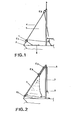
- the jib furler comprises at its base a drum 1 secured to the tack point 2 on the deck by a swivel E1 and to the halyard point 3 at the top of the mast, by a second swivel E2 between which the luff 4 of the jib 5 is stretched.
- a swivel E1 secured to the tack point 2 on the deck by a swivel E1 and to the halyard point 3 at the top of the mast, by a second swivel E2 between which the luff 4 of the jib 5 is stretched.
- the drum 1 and the upper swivel E2 are connected by a rotating forestay on which the jib is bent (fastened) with carabiners.
- the rotating forestay is provided with one or two grooves, in which the headline cord of the sail can slide.
- These grooves can be an integral part of the rotating forestay or be made by means of a metal or plastic sheath.
- the jib can be easily removed during periods of non-use.
- halyard passing over a pulley disposed under the swivel E2 at the top of the rotating forestay, the end of the halyard being, after having hoisted the jib, secured (struck) with the reel drum secured to the rotating forestay
- the halyard 7 being fixed, it must therefore, in order not to wrap around the forestay, be connected to the jib halyard point by a swivel slide E 3. If this embodiment gives satisfaction, and allows to ensure a good stretching of the sail while leaving the possibility of reducing the surface by winding around its luff, it requires the use of three swivels which must have very high mechanical characteristics given they must withstand the tension of the forestay before, tension which can reach several tons or at least the tension of the luff which which, although being weaker, can however reach several hundreds of deca-Newtons (dN).
- dN deca-Newtons
- the object of the present invention is precisely a simple, robust and reliable device, allowing the installation, the maintenance, the winding of a sail, in particular of a jib, along its luff, in order to modify the surface, a device which overcomes the drawbacks of previous devices and in particular eliminates the use of delicate and expensive ball bearings, while leaving the possibility of using the normal halyards of the boat to hoist and set the sail associated with said device.
- the device according to the invention for the installation, the maintenance and the winding of a sail
- device which, in the following description will also be designated by the expression "jib furler”
- the sail is subject to a mandrel capable of rotating around the fixed stay and which comprises at least one groove in which the headline cord of the sail can slide, said rotating mandrel being associated with means making it possible to drive it in rotation, such as than a take-up drum, so as to cause the reduction of the surface of the sail by winding on the periphery of the mandrel.
- the device according to the invention is characterized in that the tubular element comprises three parallel grooves, extending over its entire length, substantially along the generatrices. the angle at the top of the sector occupied by the three gorges being less than about one hundred and twenty (120 °) degrees, and the outer edges of said grooves serving as a guiding and holding element for a second slide called “trigger slide” comprising means capable of causing the opening of the retractable lock and, by following, the release of the carrier slider, this second slider partially surrounding the tubular element so as to leave the grooves which it comprises visible and unobstructed and being arranged below the carrier slider and being able to be moved independently of the latter along the tubular element.
- a second slide comprising means capable of causing the opening of the retractable lock and, by following, the release of the carrier slider, this second slider partially surrounding the tubular element so as to leave the grooves which it comprises visible and unobstructed and being arranged below the carrier slider and being able to be moved independently of the latter along the tubular element.
- the tubular element according to the invention is constituted by the fitting of elements of short length, around the existing forestay, the rotation of these elements around the forestay being advantageously ensured by bearings.
- the assembly of the short tubular elements is obtained by fitting, each element comprising, at one of its ends, a split sleeve, which is inserted by pressing into the preceding element, a raised rib being provided on an interior generatrix of each element, so as to serve as a guide for the split sleeves.
- the split sleeves are preferably secured at the end of each tubular element, for example by gluing or any other equivalent means.
- the tubular element can be associated with means making it possible, when the surface of the sail is reduced by surrounding it around the periphery of the mandrel, to compensate for the excess thicknesses that said sail can have ( reinforcement of halyard and tack points) so as to constantly obtain, by winding, a strictly flat residual surface.
- These means may for example be constituted by a rod, subject to the central groove, outside the (or the) zone where the sail has extra thicknesses.
- the device according to the invention for setting up, maintaining and winding a sail, is of the type according to which the sail 10 is subject to the tack 11 on the deck and to the point halyard 12 at the top of the mast 13 by means of a rotating mandrel having at least one groove in which the line of the sail 10 can slide.
- This rotary mandrel is associated with means allowing it to be rotated, such as a winding drum 14 per se known, in order to cause the winding 10 to wind around the periphery of the rotary mandrel.
- the rotating mandrel is constituted by a tubular element 15, rigid, mounted to rotate freely around a fixed co-axial forestay connecting the tack 11 on the bridge to the halyard point 12 at the top of the mast.
- This tubular element 15 rests by its lower part on a stop integral with the fixed stay 16.
- the tubular element 15 is mounted around the fixed co-axial stay 16 and the stop secured to this fixed stay 16 is constituted, in this embodiment, by a bearing 17, made for example of stainless steel, secured of the yoke of the turnbuckle 18 and which supports a bearing 19, for example made of polyamide. whose diameter corresponds to the internal diameter of the tubular element 15. Furthermore, as can be seen in this fig.
- the drum 14 for rotating the tubular element 15 is constituted by two notched flanges 20 and 21, one of which 20 is carried by the tubular end 15 and the other of which is fixed to the first .
- the rotation drive of the drum 14 is preferably ensured by a reciprocating rope 42 (Fig. 6) maintained in tension by a return pulley 43 and an elastic tensioner 44 secured to the bridge.
- the upper part of the tubular element 15 has a retractable lock 22, normally in the closed position and essentially constituted by a hook 23 subjected to the action of a return member.
- the tubular element 15 is associated with means for opening the retractable lock 22, these means possibly being constituted by a simple return cord.
- they are formed by a second slide 33 partially surrounding the tubular element 15 so as to leave free the grooves that it has, said slide 33 being disposed below the support slide 24 and having means capable of causing the opening of the retractable lock 22.
- the tubular element 15 is produced from short length assemblies 15a and 15b, fitted one inside the other, around a fixed stay 16.
- the connection of these elements to each other is obtained by means of split tubes 34, serving as n assembly anchors between the various elements 15a - 15b, these elements comprising a rib 35 whose width corresponds to the width of the slot 36 of the sleeves 34.
- split tubes 34 serving as n assembly anchors between the various elements 15a - 15b, these elements comprising a rib 35 whose width corresponds to the width of the slot 36 of the sleeves 34.
- a such an embodiment allows perfect alignment of the grooves 37, 38 and 39 that the tubular element 15 has.
- pads 40 for example based on polyamide, such as that sold under the brand Rilsan (polyamide 11), these pads being insensitive to the action of sea water.
- the use of such pads is made possible thanks to the invention, by the fact that the tubular element 15 does not support the tension of the forestay before kept inside said tubular element 15. As a result, the pads 40 have practically no load to be supported, the lower pad 19 supporting only the weight of the tube and that of the sail (of the order of a few tens of kgs.)
- pads 40 are advantageously produced in two symmetrical parts 40a-40b (FIG. 10) and delimit a groove 41 corresponding to the rib 35 of the tube, which makes it possible to make these elements integral in rotation.
- These bearings are assembled by placing them on either side of the forestay 16 and pushing them back inside each element 15a-15b, in particular by the split sleeve 34.
- Such an embodiment makes it possible to obtain a tubular element having a sufficient diameter and having a high moment of inertia to resist twisting when it is subjected to the torsional torque applied to its base by the winding drum 14.
- tubular element of hollow cylindrical section with thin walls, of forty (40) millimeters in diameter, from a light alloy, weighing seven hundred and fifty (750) grams per meter and supporting without permanent deformation a torque of 29 m / Kgf (29 m Dn).
- the production of the tubular element 15 from elements of short length, carrying a rib 35 on an internal generator ensures precise guidance of the split sleeves 34 and guarantees the transmission of the torsional torque from an element to the other without any play, while ensuring the freedom of longitudinal translation required for possible disassembly of the elements.
- the tubular element 15 has on its outer face three grooves aligned side by side, 37, 38, 39. These grooves extend over the entire length and the angle at the top the sector they occupy is preferably less than one hundred and twenty (120 °) degrees. These grooves, in known manner, are used for two of them (37 and 39) to maintain the headline cord of the sail 10, the third (central groove 38) being a service groove used, either for introducing or circulate accessories there (assembly rods and oscillating chargers), or to have, when the tubular element 15 is made from elements of short length, connecting rods reinforcing the connection between these various elements.
- the carrying slide 24, shown on a larger scale in FIGS. 12 and 13, is shaped to wrap the tubular element 15 on which it is wedged angularly - by the outer edges of the grooves 37 and 39.
- the guide of the slide 24 and its free sliding on the tubular element is ensured by one or linings or pad 24a, internally attached and for example made of a material known under the brand of Rilsan or Teflon.
- the carrying slide 24 comprises means for connecting with the sail, these means being constituted by an elongated eye 25 extending axially at the outer periphery - of the slide 24.
- the means for engaging with the retractable latch are constituted by a keeper or a chin 27 overhanging a trigger 26 comprising a head 26a and a tail 26b which is free to slide in a bore presented by a boss 26c extending axially at the external periphery of the slide 24 opposite the eye 25.
- the tail 26b normally projects from the lower peripheral edge of the slide 24.
- the temporary connection means with the end of a halyard are preferably formed by the same eye 25 but it could be provided to make the slide 24 have an eye specific to this function.
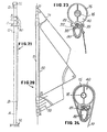
- the slide 33 called in the following trigger slide, is constituted, as appears in FIGS. 14 and 15 by an envelope open axially so as to be able to be threaded on the tubular element 15 while releasing the grooves 37 to 39.
- the axial opening of the envelope is chosen so that the edges cooperate with the wings of the extreme grooves 37 and 39 which thus ensure the angular immobilization.
- the trigger slide 33 has, opposite its axial opening, a cylindrical housing 33a in which is housed a spring 33b kept compressed between a stop 33c and a head 33d.
- the slide 33 also comprises, from its outer periphery, an eye 45 extending axially while being located in one of the sectors comprised between the boss 33a and the axial opening.
- the tack of the sail in the present case of the jib, is necessarily applied to one eye 14a of the winding pulley 14, its halyard point being struck (secured) on the eye 25 of the guide slide 24 guided on tube 15.
- a halyard 29 which passes around a pulley 30 placed at the head of the mast and terminates in a winch or winding winch 31 (fig. 3).
- the connection between the slide 24 and the halyard 29 is established by means of a crocnet 28 provided at the end of the latter and is having, as illustrated in FIG. 16, in an open form, closed by a gate 47, for example based on elastomer, sufficiently stiff so that said hook cannot be detached under the influence of its weight but can be released by a traction exerted on a cord callback 48 struck at the foot of the mast.
- the flange 27 of the slide 24 engages, at the top of the tubular element 15, under the retractable latch 22, and more particularly under the hook 23 normally maintained in the closed position, for example by a spring 70
- the engagement (fig. 17) being operated the tension of the halyard 29 can be released since, thanks to the hook 23, the tension of tensioning of the luff is then supported by the tubular element 15 (fig. 4).
- a pull on the return cord 48 releases the open hook 28 from the slide and allows the halyard to be brought back to the foot of the mast. Completely separated from the tubular element supporting the sail, the halyard 29 is therefore available for another use.
- the halyard 29 is this time struck by its hook 28 on the eye 45 of the trigger slide 33 stored at the base of the tubular element 15.
- the trigger slider 33 Via the halyard 29, the trigger slider 33 is hoisted along the tubular element 15 until it comes into contact with the carrying slider 24 (fig. 17). In this position the head 33d strikes the tail 26c which pushes the head back into the housing 33a, with the result of compressing the spring 33b.
- an additional effort on the halyard relieves the slider 24 and therefore frees the head of the hook 23 from the tension of the luff, which allows the trigger 26, pushed upwards by the action of the spring 33b on the rod 26b, to penetrate under the hook 23, to rotate it, then releasing the flange 27 from the slide 24, which immediately begins its descent, as soon as the halyard 29 is completely released.
- the device according to the invention can be easily adapted to obtain good flatness of the sail when it is partially wound around the tubular element 15, despite the extra thickness that it can have in particular at its ends.
- the second turn wound on the first will have an increased diameter of 2 x 3 mm and a perimeter of 140mm + ( 6) ⁇ 140 + 18 mm and so on.
- the remedy for this defect is to increase by a device the winding perimeter in the area BC between the reinforcements (fi g. 20, 21).
- the tubular element according to the invention provides a universal solution to this problem. It consists in creating a winding mandrel tube with constant profile by forming the desired increase in perimeter by applying along a generatrix of the mandrel 15, an added element, such as a rod 80, made of plastic or the like.
- a rod 80 made of plastic or the like.
- the joint 80 with the tubular element 15 can be made by bonding , riveting or any other equivalent means.
- the rod 80 can be cut into elements of similar length to
Landscapes
- Engineering & Computer Science (AREA)
- Life Sciences & Earth Sciences (AREA)
- Sustainable Development (AREA)
- Sustainable Energy (AREA)
- Chemical & Material Sciences (AREA)
- Combustion & Propulsion (AREA)
- Mechanical Engineering (AREA)
- Ocean & Marine Engineering (AREA)
- Moulding By Coating Moulds (AREA)
- Jib Cranes (AREA)
Applications Claiming Priority (2)
| Application Number | Priority Date | Filing Date | Title |
|---|---|---|---|
| FR7823656 | 1978-08-04 | ||
| FR7823656A FR2432432A1 (fr) | 1978-08-04 | 1978-08-04 | Perfectionnement aux systemes enrouleurs de focs |
Publications (2)
| Publication Number | Publication Date |
|---|---|
| EP0008560A1 true EP0008560A1 (de) | 1980-03-05 |
| EP0008560B1 EP0008560B1 (de) | 1982-02-17 |
Family
ID=9211764
Family Applications (1)
| Application Number | Title | Priority Date | Filing Date |
|---|---|---|---|
| EP79420036A Expired EP0008560B1 (de) | 1978-08-04 | 1979-07-27 | Vorsegelroller mit Reffeinrichtung |
Country Status (6)
| Country | Link |
|---|---|
| US (1) | US4267791A (de) |
| EP (1) | EP0008560B1 (de) |
| JP (1) | JPS56160294A (de) |
| AU (1) | AU532894B2 (de) |
| DE (1) | DE2962142D1 (de) |
| FR (1) | FR2432432A1 (de) |
Cited By (12)
| Publication number | Priority date | Publication date | Assignee | Title |
|---|---|---|---|---|
| US4266495A (en) * | 1979-09-13 | 1981-05-12 | Hood Ralph S | Apparatus for supporting a sail |
| FR2539380A1 (fr) * | 1983-01-13 | 1984-07-20 | Proengin | Perfectionnements apportes aux enrouleurs de foc |
| US4474127A (en) * | 1982-08-06 | 1984-10-02 | Stevenson William H Iv | Working sails and method for furling them while aloft |
| FR2555542A1 (fr) * | 1983-11-25 | 1985-05-31 | Proengin | Perfectionnements apportes aux raccordements des tubes d'enrouleur de foc et dispositifs maintenant les spires dans le tambour |
| FR2557850A1 (fr) * | 1984-01-11 | 1985-07-12 | Bretagne Sarl Tech Voile | Emerillon pour enrouleur de voile et enrouleur ainsi equipe |
| FR2572704A1 (fr) * | 1984-11-07 | 1986-05-09 | Despres Jean | Dispositif permettant de reduire par enroulement la surface d'une piece de tissu tendue entre deux points fixes, notamment enrouleur de voile |
| FR2584370A1 (fr) * | 1985-07-08 | 1987-01-09 | Isomat Sarl | Systeme enrouleur de foc pour bateau a voiles |
| FR2585325A1 (fr) * | 1985-07-29 | 1987-01-30 | Isomat Sarl | Dispositif pour hisser, maintenir hisse et affaler un foc sur un bateau a voiles |
| EP0310529A1 (de) * | 1987-10-02 | 1989-04-05 | Wichard | Automatische Arretierungsvorrichtung im hochgezogenen Stand eines Segels auf einem Segelbootmast |
| EP0541430A1 (de) * | 1991-11-07 | 1993-05-12 | Proengin S.A. | Vorsegelrollreff mit einem auf dem Vorstag verriegelbaren Wirbelgelenk |
| FR2931453A1 (fr) * | 2008-05-23 | 2009-11-27 | Jean Francois Maurras | Dispositif permettant l'etarquage d'une voile partiellement enroulee |
| ITRA20120002A1 (it) * | 2012-03-07 | 2013-09-08 | Renzo Greghi | Dispositivo di avvolgimento per vele |
Families Citing this family (10)
| Publication number | Priority date | Publication date | Assignee | Title |
|---|---|---|---|---|
| US4723499A (en) * | 1985-08-19 | 1988-02-09 | Bernard Furgang | Furling system for sailboats |
| US4821664A (en) * | 1987-06-12 | 1989-04-18 | Cruising Design, Inc. | Furling stay cover |
| DE3901591A1 (de) * | 1989-01-20 | 1990-07-26 | Guenter Nasgowitz | Segelkopfarretierung |
| US5619946A (en) * | 1995-11-29 | 1997-04-15 | Wallasch; Lutz | Sail furling device with bearings to permit simultaneous cable and extrusion rotation |
| US6971430B1 (en) * | 2003-03-19 | 2005-12-06 | Thomas Ward Omohundro | Cast composite sail and method |
| US7275491B1 (en) * | 2006-10-17 | 2007-10-02 | Schaeffer Marine, Inc. | Sail furling system with recirculating halyard |
| FR2932454B1 (fr) * | 2008-06-12 | 2010-06-18 | Olivier Luizy | Dispositif enrouleur et etarqueur de voile d'avant a guindant ralingue ou a guindant libre pour voilier. |
| US9027493B2 (en) * | 2012-08-31 | 2015-05-12 | Wichard Inc. | Sail bearing |
| ITPD20130111A1 (it) * | 2013-04-24 | 2014-10-25 | Armare Di Stefano Finco | Dispositivo avvolgitore per vele strallate e simili |
| ES1308081Y (es) * | 2024-01-16 | 2024-08-30 | Conurban Marine S L U | Accesorio de embarcación de vela |
Citations (8)
| Publication number | Priority date | Publication date | Assignee | Title |
|---|---|---|---|---|
| FR2150178A5 (de) * | 1971-08-17 | 1973-03-30 | Dowling Thomas | |
| US3749043A (en) * | 1971-11-15 | 1973-07-31 | D Crall | System for reefing and furling staysails |
| GB1340777A (en) * | 1971-11-30 | 1974-01-30 | Ss Spars Ltd | Attachment of sails of stays |
| FR2225331A1 (en) * | 1973-04-11 | 1974-11-08 | Bernard Bernard | Aerofoil shape gaff for staysail luff rope - has separate nosepiece and rotates around forestay in longitudinal slot |
| FR2243862A1 (de) * | 1973-09-18 | 1975-04-11 | Bernard Bernard | |
| US3938460A (en) * | 1974-03-04 | 1976-02-17 | Hood Sailmakers, Inc. | Sail-raising system |
| US3980036A (en) * | 1976-03-08 | 1976-09-14 | Crall Donald H | Roller furling assembly |
| DE2635717A1 (de) * | 1976-08-07 | 1978-02-09 | Guenter Nasgowitz | Reffeinrichtung mit segelarretierung |
Family Cites Families (2)
| Publication number | Priority date | Publication date | Assignee | Title |
|---|---|---|---|---|
| GB191324269A (en) * | 1913-10-27 | 1914-10-22 | Theophilus Osborn Smith | An Improved Reefing Gear for the Sails of Yachts and other Vessels. |
| US3789790A (en) * | 1971-11-15 | 1974-02-05 | D Crall | System for reefing and furling sails |
-
1978
- 1978-08-04 FR FR7823656A patent/FR2432432A1/fr active Granted
-
1979
- 1979-07-25 US US06/060,611 patent/US4267791A/en not_active Expired - Lifetime
- 1979-07-27 DE DE7979420036T patent/DE2962142D1/de not_active Expired
- 1979-07-27 EP EP79420036A patent/EP0008560B1/de not_active Expired
- 1979-08-04 JP JP9913879A patent/JPS56160294A/ja active Pending
- 1979-08-06 AU AU49599/79A patent/AU532894B2/en not_active Ceased
Patent Citations (8)
| Publication number | Priority date | Publication date | Assignee | Title |
|---|---|---|---|---|
| FR2150178A5 (de) * | 1971-08-17 | 1973-03-30 | Dowling Thomas | |
| US3749043A (en) * | 1971-11-15 | 1973-07-31 | D Crall | System for reefing and furling staysails |
| GB1340777A (en) * | 1971-11-30 | 1974-01-30 | Ss Spars Ltd | Attachment of sails of stays |
| FR2225331A1 (en) * | 1973-04-11 | 1974-11-08 | Bernard Bernard | Aerofoil shape gaff for staysail luff rope - has separate nosepiece and rotates around forestay in longitudinal slot |
| FR2243862A1 (de) * | 1973-09-18 | 1975-04-11 | Bernard Bernard | |
| US3938460A (en) * | 1974-03-04 | 1976-02-17 | Hood Sailmakers, Inc. | Sail-raising system |
| US3980036A (en) * | 1976-03-08 | 1976-09-14 | Crall Donald H | Roller furling assembly |
| DE2635717A1 (de) * | 1976-08-07 | 1978-02-09 | Guenter Nasgowitz | Reffeinrichtung mit segelarretierung |
Cited By (16)
| Publication number | Priority date | Publication date | Assignee | Title |
|---|---|---|---|---|
| US4266495A (en) * | 1979-09-13 | 1981-05-12 | Hood Ralph S | Apparatus for supporting a sail |
| US4474127A (en) * | 1982-08-06 | 1984-10-02 | Stevenson William H Iv | Working sails and method for furling them while aloft |
| FR2539380A1 (fr) * | 1983-01-13 | 1984-07-20 | Proengin | Perfectionnements apportes aux enrouleurs de foc |
| FR2555542A1 (fr) * | 1983-11-25 | 1985-05-31 | Proengin | Perfectionnements apportes aux raccordements des tubes d'enrouleur de foc et dispositifs maintenant les spires dans le tambour |
| FR2557850A1 (fr) * | 1984-01-11 | 1985-07-12 | Bretagne Sarl Tech Voile | Emerillon pour enrouleur de voile et enrouleur ainsi equipe |
| FR2572704A1 (fr) * | 1984-11-07 | 1986-05-09 | Despres Jean | Dispositif permettant de reduire par enroulement la surface d'une piece de tissu tendue entre deux points fixes, notamment enrouleur de voile |
| FR2584370A1 (fr) * | 1985-07-08 | 1987-01-09 | Isomat Sarl | Systeme enrouleur de foc pour bateau a voiles |
| FR2585325A1 (fr) * | 1985-07-29 | 1987-01-30 | Isomat Sarl | Dispositif pour hisser, maintenir hisse et affaler un foc sur un bateau a voiles |
| EP0310529A1 (de) * | 1987-10-02 | 1989-04-05 | Wichard | Automatische Arretierungsvorrichtung im hochgezogenen Stand eines Segels auf einem Segelbootmast |
| FR2621295A1 (fr) * | 1987-10-02 | 1989-04-07 | Wichard | Dispositif d'accrochage automatique en position haute de la tete d'une voile d'un bateau a voile sur le mat de celui-ci |
| EP0541430A1 (de) * | 1991-11-07 | 1993-05-12 | Proengin S.A. | Vorsegelrollreff mit einem auf dem Vorstag verriegelbaren Wirbelgelenk |
| FR2683501A1 (fr) * | 1991-11-07 | 1993-05-14 | Proengin | Enrouleur-reducteur de voilure a emerillon verrouillable sur l'etai. |
| FR2931453A1 (fr) * | 2008-05-23 | 2009-11-27 | Jean Francois Maurras | Dispositif permettant l'etarquage d'une voile partiellement enroulee |
| WO2009153479A3 (fr) * | 2008-05-23 | 2010-02-18 | Maurras Jean-Francois | Dispositif permettant l'etarquage d'une voile partiellement enroulee. |
| ITRA20120002A1 (it) * | 2012-03-07 | 2013-09-08 | Renzo Greghi | Dispositivo di avvolgimento per vele |
| WO2013132302A1 (en) * | 2012-03-07 | 2013-09-12 | Renzo Greghi | Furling device for furling sails |
Also Published As
| Publication number | Publication date |
|---|---|
| US4267791A (en) | 1981-05-19 |
| FR2432432A1 (fr) | 1980-02-29 |
| EP0008560B1 (de) | 1982-02-17 |
| AU532894B2 (en) | 1983-10-20 |
| JPS56160294A (en) | 1981-12-09 |
| DE2962142D1 (en) | 1982-03-25 |
| AU4959979A (en) | 1980-02-07 |
| FR2432432B1 (de) | 1981-10-23 |
Similar Documents
| Publication | Publication Date | Title |
|---|---|---|
| EP0008560B1 (de) | Vorsegelroller mit Reffeinrichtung | |
| EP2576414B1 (de) | Vorrichtung zum ergreifen und einstellen der spannung eines länglichen elements wie eines kabels, seils oder dergleichen | |
| EP0011582A1 (de) | Verbesserung an Systemen zum Aufrollen eines Segels | |
| CA1079581A (fr) | Dispositif de controle des debattements de la bome d'un voilier | |
| EP1183180B1 (de) | Gerät zum anschlagen von segeln | |
| EP2133261B1 (de) | Vorrichtung zum Aufrollen und Durchspannen eines flatternden Vordersegels (Fock) oder eines freien Vorlieks für Segelboot | |
| FR2719034A1 (fr) | Système de mouflage à plusieurs multiplications, à simple ligne. | |
| FR2475514A1 (fr) | Treuil de pont de bateau, a entrainement manuel | |
| EP0541430B1 (de) | Vorsegelrollreff mit einem auf dem Vorstag verriegelbaren Wirbelgelenk | |
| EP0141766B1 (de) | Sicherungseinrichtung zum Einhaken des Segelkopfes an der Mastspitze | |
| EP2574541A1 (de) | Fockroller für ein vorderes Segel um einen Vorstag von einem Segelboot | |
| EP0204051A1 (de) | Segelreffeinrichtung und Baum mit dieser Einrichtung | |
| FR3001517A1 (fr) | Bloqueur de cordage. | |
| FR2579168A1 (fr) | Enrouleur-reducteur de voilure perfectionne, pour bateau a voiles | |
| EP0310529A1 (de) | Automatische Arretierungsvorrichtung im hochgezogenen Stand eines Segels auf einem Segelbootmast | |
| EP1765666A1 (de) | Vorrichtung zum verstauen und ausweiten eines frontsegels eines segelboots | |
| FR2794447A1 (fr) | Dispositif bloqueur de cordage | |
| FR3152793A1 (fr) | Systeme pour hisser et abaisser la voile d’un voilier | |
| FR2698067A1 (fr) | Système perfectionné pour l'enroulement et la manÓoeuvre à distance d'un spinnaker. | |
| FR2584994A1 (fr) | Bome enrouleuse composite pour l'enroulement d'une voile de bateau | |
| FR3137056A1 (fr) | Système de blocage et de déblocage d’élément longiligne avec enveloppe et deux éléments de fixation, un à chaque extrémité de l’enveloppe | |
| FR2724373A1 (fr) | Etarqueur a galet | |
| WO2006051207A1 (fr) | Dispositif de guidage de la ralingue d'une voile | |
| EP0891924A1 (de) | Gerät zur Optimierung der Stellung eines Rollbaumes hinsichtlich guter Segel-Wickeleigenschaften | |
| FR2539380A1 (fr) | Perfectionnements apportes aux enrouleurs de foc |
Legal Events
| Date | Code | Title | Description |
|---|---|---|---|
| PUAI | Public reference made under article 153(3) epc to a published international application that has entered the european phase |
Free format text: ORIGINAL CODE: 0009012 |
|
| AK | Designated contracting states |
Designated state(s): DE GB IT NL SE |
|
| 17P | Request for examination filed | ||
| ITF | It: translation for a ep patent filed | ||
| GRAA | (expected) grant |
Free format text: ORIGINAL CODE: 0009210 |
|
| AK | Designated contracting states |
Designated state(s): DE GB IT NL SE |
|
| REF | Corresponds to: |
Ref document number: 2962142 Country of ref document: DE Date of ref document: 19820325 |
|
| PGFP | Annual fee paid to national office [announced via postgrant information from national office to epo] |
Ref country code: DE Payment date: 19840622 Year of fee payment: 6 |
|
| PGFP | Annual fee paid to national office [announced via postgrant information from national office to epo] |
Ref country code: SE Payment date: 19840630 Year of fee payment: 6 |
|
| PGFP | Annual fee paid to national office [announced via postgrant information from national office to epo] |
Ref country code: NL Payment date: 19860731 Year of fee payment: 8 |
|
| PG25 | Lapsed in a contracting state [announced via postgrant information from national office to epo] |
Ref country code: SE Effective date: 19870728 |
|
| PG25 | Lapsed in a contracting state [announced via postgrant information from national office to epo] |
Ref country code: NL Effective date: 19880201 |
|
| NLV4 | Nl: lapsed or anulled due to non-payment of the annual fee | ||
| PG25 | Lapsed in a contracting state [announced via postgrant information from national office to epo] |
Ref country code: DE Effective date: 19880401 |
|
| GBPC | Gb: european patent ceased through non-payment of renewal fee | ||
| PG25 | Lapsed in a contracting state [announced via postgrant information from national office to epo] |
Ref country code: GB Free format text: LAPSE BECAUSE OF NON-PAYMENT OF DUE FEES Effective date: 19881118 |
|
| EUG | Se: european patent has lapsed |
Ref document number: 79420036.0 Effective date: 19880831 |
|
| PLBE | No opposition filed within time limit |
Free format text: ORIGINAL CODE: 0009261 |
|
| STAA | Information on the status of an ep patent application or granted ep patent |
Free format text: STATUS: NO OPPOSITION FILED WITHIN TIME LIMIT |