EP2574541A1 - Fockroller für ein vorderes Segel um einen Vorstag von einem Segelboot - Google Patents
Fockroller für ein vorderes Segel um einen Vorstag von einem Segelboot Download PDFInfo
- Publication number
- EP2574541A1 EP2574541A1 EP12185156A EP12185156A EP2574541A1 EP 2574541 A1 EP2574541 A1 EP 2574541A1 EP 12185156 A EP12185156 A EP 12185156A EP 12185156 A EP12185156 A EP 12185156A EP 2574541 A1 EP2574541 A1 EP 2574541A1
- Authority
- EP
- European Patent Office
- Prior art keywords
- outer ring
- winding system
- locking
- sail
- sailboat
- Prior art date
- Legal status (The legal status is an assumption and is not a legal conclusion. Google has not performed a legal analysis and makes no representation as to the accuracy of the status listed.)
- Withdrawn
Links
- 238000000034 method Methods 0.000 claims abstract description 12
- 238000006073 displacement reaction Methods 0.000 claims abstract description 11
- 238000004804 winding Methods 0.000 claims description 51
- FGUUSXIOTUKUDN-IBGZPJMESA-N C1(=CC=CC=C1)N1C2=C(NC([C@H](C1)NC=1OC(=NN=1)C1=CC=CC=C1)=O)C=CC=C2 Chemical compound C1(=CC=CC=C1)N1C2=C(NC([C@H](C1)NC=1OC(=NN=1)C1=CC=CC=C1)=O)C=CC=C2 FGUUSXIOTUKUDN-IBGZPJMESA-N 0.000 claims description 2
- 241001125831 Istiophoridae Species 0.000 description 9
- 239000002184 metal Substances 0.000 description 5
- 239000004753 textile Substances 0.000 description 4
- 241001080024 Telles Species 0.000 description 2
- 230000005540 biological transmission Effects 0.000 description 2
- 230000035515 penetration Effects 0.000 description 2
- 230000002093 peripheral effect Effects 0.000 description 2
- 230000002028 premature Effects 0.000 description 2
- 238000012800 visualization Methods 0.000 description 2
- KRBMQYPTDYSENE-BQBZGAKWSA-N His-Ser Chemical compound OC[C@@H](C(O)=O)NC(=O)[C@@H](N)CC1=CNC=N1 KRBMQYPTDYSENE-BQBZGAKWSA-N 0.000 description 1
- 230000000903 blocking effect Effects 0.000 description 1
- 230000005484 gravity Effects 0.000 description 1
- 108010018006 histidylserine Proteins 0.000 description 1
- 229920002994 synthetic fiber Polymers 0.000 description 1
Images


Classifications
-
- B—PERFORMING OPERATIONS; TRANSPORTING
- B63—SHIPS OR OTHER WATERBORNE VESSELS; RELATED EQUIPMENT
- B63H—MARINE PROPULSION OR STEERING
- B63H9/00—Marine propulsion provided directly by wind power
- B63H9/04—Marine propulsion provided directly by wind power using sails or like wind-catching surfaces
- B63H9/08—Connections of sails to masts, spars, or the like
- B63H9/10—Running rigging, e.g. reefing equipment
- B63H9/1021—Reefing
- B63H9/1028—Reefing by furling around stays
Definitions
- the present invention relates to a system for winding a front sail around a stay supporting a mast of a sailboat, and more particularly a winding system of a forward sail directly around a sail. a support stay of a mast of a sailboat.
- the first and third elements are arranged to allow, in use, a rotation of the support stay about its axis so as to allow the winding of the forward sail directly. around the support stay which then forms a winding mandrel.
- a halyard of the sailboat circulating in a pulley fixed permanently at the top of the mast, to connect a first end of the halyard at the second mounting portion of the second element, to exert traction on a second end of the halyard so as to position the forward sail, and finally to block the second end of the halyard at the foot of the mast.
- the present invention aims to remedy these disadvantages.
- the technical problem underlying the invention is therefore to provide a winding system of a sail before which is simple and economical structure, and can be used on any type of sailboat.
- the winding system according to the invention can be used on a sailboat provided with a non-metallic support strut, and for example textile, without risk of premature wear of the latter. Since a textile support strut provides optimum torque transmission to the forward sail when wrapped around the support strut, regardless of the size of the forward sail and the support forest, the winding system according to the invention is therefore usable on sailboats of great heights.
- the halyard used to hoist the element on which is fixed the front sail can be disconnected from this element after locking it on the other element, and then used for other applications.
- the presence of the remote control means makes it possible to ensure that the front sail is balanced without having to climb to the top of the mast, which makes it possible to secure the user when the sail is lowered.
- the element adapted to be fixed on the upper part of the mast comprises a first fixing portion intended to be fixed on the upper part of the mast, and a second fixing portion on which is intended to be fixed the upper end of the mast.
- the strut, the second fixing portion being rotatably mounted relative to the first fixing portion so as to allow, in use, a rotation of the support strut about its axis.
- the second fixing portion is advantageously mounted free to rotate relative to the first fixing portion about an axis of rotation substantially parallel to the axis of the first fixing portion.
- the element adapted to be fixed on the upper corner of the forward sail comprises a first mounting portion on which is intended to be mounted the upper corner of the forward sail, and a second mounting portion on which is intended to be mounted a halyard of the sailboat.
- the element adapted to be fixed on the upper corner of the forward sail is adapted to be mounted on the support strut so as to allow movement of said element along the 'prop.
- the element adapted to be mounted movably on the strut defines a passage conduit for the passage of the strut.
- the second element comprises a tubular portion adapted to receive the first element in the locking position of the second element on the first element.
- the locking means comprise a plurality of balls each mounted in a through bore formed in the tubular portion of the second element, each ball being movable between a locking position in which it cooperates with the first element so as to lock the first and second elements one on the other, and an unlock position.
- each ball in the locking position protrudes inside the sleeve and each ball in the unlocked position does not protrude inside the sleeve.
- Each ball is advantageously displaceable radially between its locking and unlocking positions.
- the second element comprises an outer ring slidably mounted around the tubular portion of the second element substantially along the axis of the tubular portion between a first position in which the outer ring blocks each ball in its locking position, and a second position in which the outer ring allows a movement of each ball to its unlocked position.
- the outer ring is rotatably mounted relative to the tubular portion of the second element.
- the second element comprises an inner ring slidably mounted in the tubular portion of the second element substantially along the axis of the tubular portion between a first position in which the inner ring blocks each ball in its position. unlocking, and a second position in which the inner ring allows a movement of each ball to its locking position.
- the balls in the unlocking position are arranged to immobilize the outer ring in its second position, and the balls in the locking position are arranged to release the outer ring and allow movement of the outer ring to its first position.
- the first element comprises an actuating portion arranged to cooperate with the inner ring and to displace this last to its second position when the tubular portion of the second element accommodates the first element.
- the outer ring comprises a first portion having a first inner diameter and a second portion having a second inner diameter greater than the first diameter, the first portion being arranged to cooperate with the balls and immobilize the latter. in their locking position when the outer ring is in its first position, the second portion being arranged to allow movement of the balls to their unlocking position when the outer ring is in its second position.
- the outer ring has an inclined ramp formed on the inner surface of the outer ring and arranged to bias the balls towards their locking position during movement of the outer ring to its first position.
- the inclined ramp is preferably formed between the first and second portions of the outer ring.
- the second element comprises first return means arranged to bias the outer ring towards its first position.
- the second element comprises second return means arranged to bias the inner ring towards its first position.
- the first element comprises an annular groove adapted to receive the balls in the locking position of the second element on the first element.
- control means comprise a traction member, such as a rope, cable or the like, connected to the outer ring and arranged to move the outer ring to its second position when a traction is exerted on the traction member.
- a traction member such as a rope, cable or the like
- the second mounting portion is formed by a handle mounted on the outer ring.
- the traction member is fixed on the handle mounted on the outer ring.
- the winding system comprises a third element intended to be mounted on the deck of the sailboat and on which is intended to be mounted the lower end of the strut, the third element being arranged to allow, in use, a rotation of the support stay about its axis.
- the third element preferably comprises a first fixing portion intended to be fixed on the deck of the sailboat, and a second fixing portion on which is intended to be fixed the lower end of the stay, the second fixing portion being mounted free in rotation relative to the first fixing portion so as to allow, in use, a rotation of the support strut about its axis.
- the second fixing portion of the third element is preferably arranged to allow the rotation of the support prop around its axis.
- the second fixing portion of the third element is for example formed by a drum or a drive turret.
- the second element is adapted to be mounted movably along the forestay and adapted to be fixed on the upper corner of the forward sail.
- the tubular portion of the second element defines the passage duct of the second element, the passage duct being intended to receive the first element in the locking position of the latter.
- the winding system advantageously comprises stop means arranged to limit the displacement stroke of the outer ring to its first position, and preferably stop means arranged to limit the displacement stroke of the inner ring to its first position.
- the winding system preferably comprises at least one lock indicator, advantageously brightly colored, designed to signal a state of locking or unlocking of the second element on the first element.
- the step of disconnecting the halyard makes it possible to avoid any risk of winding the halyard around the support forestay during a winding of the forward sail around the latter.
- step f) consists in exerting traction on the rope connected to the locking means of the carabiner so as to move the latter to their release position to release the element on which is fixed the upper corner of the sail before.
- the step of connecting a rope or the like to the locking means of the carabiner comprises a step of connecting a textile ring to the locking means, for example by knotting, and a step of connecting the rope or the like to the textile ring.
- step c) comprises a step of mounting the other of the first and second elements on the support strut.
- the hoisting method comprises a step of introducing the traction member belonging to the control means in the sheath of the forward sail.
- Step e) can for example be performed using a winch of the boat.
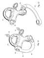
- the winding system comprises a first element 2 intended to be fixed in the upper part of a mast 3 of a sailboat and on which is intended to be fixed the upper end of a support strut 4 of the mast 3, a second element 5 adapted to be mounted movably around and along the support stay 4 of the mast 3 and on which is intended to mount the upper corner of a front sail 6, and a third element 8 to be fixed on deck 9 of the sailboat and on which is intended to be fixed at the lower end of the support strut 4.
- the first and third elements are arranged to allow, under use, a rotation of the support strut around its axis so as to allow the winding of the forward sail directly around the support stay which then forms a winding mandrel.
- the first element 2 is formed by a swivel.
- the first element 2 comprises a first fixing portion 11 intended to be fixed in the upper part of the mast 3, and a second fixing portion 12 on which is intended to be fixed the upper end of the support strut 4.
- the second fixing portion 12 is mounted free to rotate with respect to the first fastening portion 11 about an axis of rotation substantially parallel to the axis of the first portion 11.
- the second fastening portion 12 comprises a threaded portion 13 arranged to cooperate with a threaded portion 14 formed at the upper end of the support strut 4.
- the second fastening portion 12 also comprises an annular groove 15 extended towards the threaded portion 14 by an annular projection 16.
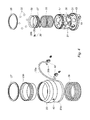
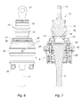
- the second element 5 comprises a tubular sleeve 17 defining a passage duct 18 intended for the passage of the support stay 4, as shown in particular on the figure 7 .
- the passage duct 18 is further adapted to receive the first element 2 in the locking position of the second element 5 on the first element 2, as will be explained hereinafter.
- the second element 5 further comprises two mounting eyelets 19 integral with one end of the tubular sleeve 17 and intended for mounting the upper corner of the front sail 6.
- the tubular sleeve 17 has a plurality of bores 21 formed radially through the wall of the tubular sleeve 17. Each bore 21 forms a housing for a locking ball 22. Each ball 22 is radially displaceable between a locking position (shown in FIG. figure 11 ) in which it protrudes inside the sleeve 17 and an unlocking position (shown on the figure 7 ) in which it does not protrude inside the sleeve 17. Each ball 22 in the locking position is intended to be received in the annular groove 15 formed in the first element 2.
- the second element 5 further comprises an outer ring 23 slidably mounted around the tubular sleeve 17 along the axis of the tubular sleeve 17 between a first position in which the outer ring 23 biases each ball 22 to its locking position, and a second position in which the outer ring 23 allows a movement of each ball 22 to its unlocked position.
- the outer ring 23 has a first portion 24 having a first inner diameter and a second portion 25 having a second inner diameter greater than the first diameter.
- the first portion 24 is arranged to cooperate with the balls 22 and immobilize the latter in their locking position when the outer ring 23 is in its first position, while the second portion 25 is arranged to allow movement of the balls 22 to their position unlocking when the outer ring 23 is in its second position.
- the outer ring 23 further comprises an inclined ramp 26 formed on the inner surface of the outer ring 23 and between the first and second portions 24, 25.
- the inclined ramp 26 is arranged to bias the balls 22 towards their locking position during the moving the outer ring 23 to its first position.
- the outer ring 23 comprises a body 23a made of synthetic material, and a metal insert 23b immobilized with respect to the body 23a with the help of a ring of retainer 27 mounted on the body 23a and a stop surface 28 formed on the body 23a.
- the first and second portions 24, 25 and the inclined ramp 26 are formed by the metal insert 23b.
- the second element 5 further comprises a return spring 29 arranged to bias the outer ring 23 to its first position.
- the return spring 29 has a first end bearing against an external peripheral return 31 extending radially from the outer surface of the tubular sleeve 17, and a second end bearing against the outer ring 23.
- the second element 5 also comprises an inner ring 32 slidably mounted in the tubular sleeve 17 along the axis of the latter between a first position in which the inner ring 32 urges each ball 22 towards its unlocking position, and a second position in which the inner ring 32 allows a movement of each ball 22 to its locking position.
- the second element 5 comprises a return spring 33 arranged to urge the inner ring 32 to its first position.
- the return spring 33 has a first end bearing against an inner peripheral return 34 extending radially from the inner surface of the tubular sleeve 17, and a second end bearing against the inner ring 17.
- the annular projection 16 of the first element 2 is arranged to cooperate with the inner ring 32 and move the latter to its second position when the passage duct 18 of the second element 5 accommodates the first element 2.
- the balls 22 are arranged on the one hand to immobilize the outer ring 23 in its second position when the inner ring 32 is in its first position, and on the other hand to release the outer ring 23 when the inner ring 32 is moved to its second position.
- the second element 5 comprises first stop means arranged to limit the displacement stroke of the outer ring 23 to its first position, and second stop means arranged to limit the displacement stroke of the inner ring 32 to its first position.
- the first stop means comprise a retaining ring 35 mounted on the outer surface of the tubular sleeve 17 and arranged to cooperate with the retaining ring 27 mounted on the body 23a of the outer ring 23.
- the second stop means comprise two members stopper 36 each having a mounting portion 36a inserted in an orifice 37 in the inner ring 32, and a stop portion 36b protruding outside the inner ring 32 and extending through an opening 38 in the tubular sleeve 17.
- the abutment portion 36b of each stop member 36 is arranged to cooperate with the wall defining the corresponding opening 38 when the inner ring 32 is in its first position.
- the second element 5 finally comprises a mounting loop 39 mounted on the outer ring 23 and on which is intended to be mounted a halyard 46 of the sailboat to ensure a displacement of the second member 5 along the support strut 4.
- the mounting loop 39 has a central portion 39a and two end portions 39b each inserted into a hole 40 each orifice 40 opens into an annular groove 41 formed in the inner surface of the outer ring 23.
- the second element 5 comprises two retaining members 42 housed in the annular groove 41. Each retaining member 42 is arranged to retain an end portion 39b of the mounting handle 39.
- the winding system comprises a locking indicator 43, advantageously brightly colored, designed to signal a state of locking or unlocking of the second element 5 on the first element 2.
- the locking indicator 43 is disposed on the outer surface of the return external device 31.
- the outer ring 23 is arranged to cover the locking indicator 43 when it is in its second position, and make visible the lock indicator when it is in its first position.
- the winding system comprises a traction member 44, such as a rope, cable or the like, fixed on the mounting handle 39 and arranged to move the outer ring 23 to its second position when traction is exerted on the pulling member.
- the traction member 44 thus makes it possible to remotely control the displacement of the locking balls 22 towards their unlocking position.
- the traction member 44 is advantageously intended to be disposed inside the sheath of the front sail 6.
- the third element 8 comprises a first fastening portion 8a intended to be fixed on the deck 9 of the sailboat, and a second fastening portion 8b on which the lower end of the support strut 4 is intended to be fixed.
- second securing portion 8b is mounted free to rotate relative to the first fastening portion 8a about an axis of rotation substantially parallel to the axis of the first fastening portion 8a.
- the method of slackening the front sail 6 with the aid of the winding system comprises a step consisting in exercising a traction on the traction member 44 so as to move the outer ring 23 to its second position and cause a movement of the balls 22 to their unlocked position. This results in a gravity fall of the second element 5 and the forward sail 6 along the support strut. The fall of the front sail 6 is braked by sliding of the sheath thereof along the support strut 4.
- the luffing method further comprises the steps of opening the sheath of the front sail 6 so as to disconnect the latter from the support strut 4, and to disconnect the upper corner of the front sail 6 of the second element 5.
- the invention is not limited to the sole embodiment of this winding system, described above as an example, it encompasses all the variants.
Landscapes
- Engineering & Computer Science (AREA)
- Life Sciences & Earth Sciences (AREA)
- Sustainable Development (AREA)
- Sustainable Energy (AREA)
- Chemical & Material Sciences (AREA)
- Combustion & Propulsion (AREA)
- Mechanical Engineering (AREA)
- Ocean & Marine Engineering (AREA)
- Emergency Lowering Means (AREA)
Applications Claiming Priority (1)
| Application Number | Priority Date | Filing Date | Title |
|---|---|---|---|
| FR1158852A FR2980765B1 (fr) | 2011-09-30 | 2011-09-30 | Systeme d'enroulement d'une voile d'avant autour d'un etai de soutien d'un mat d'un voilier |
Publications (1)
| Publication Number | Publication Date |
|---|---|
| EP2574541A1 true EP2574541A1 (de) | 2013-04-03 |
Family
ID=46832306
Family Applications (1)
| Application Number | Title | Priority Date | Filing Date |
|---|---|---|---|
| EP12185156A Withdrawn EP2574541A1 (de) | 2011-09-30 | 2012-09-20 | Fockroller für ein vorderes Segel um einen Vorstag von einem Segelboot |
Country Status (2)
| Country | Link |
|---|---|
| EP (1) | EP2574541A1 (de) |
| FR (1) | FR2980765B1 (de) |
Cited By (3)
| Publication number | Priority date | Publication date | Assignee | Title |
|---|---|---|---|---|
| ITBO20130543A1 (it) * | 2013-10-02 | 2015-04-03 | Gianni Dini | Dispositivo di avvolgimento per vele |
| EP3099568A4 (de) * | 2014-01-28 | 2017-11-01 | Harken, Incorporated | Von oben nach unten aufrollsystem |
| FR3088302A1 (fr) * | 2018-11-09 | 2020-05-15 | Fabrication D'accastillage Normand | Systeme d'accrochage amovible d'une voile sur une zone d'un navire permettant l'enroulement de la voile |
Citations (3)
| Publication number | Priority date | Publication date | Assignee | Title |
|---|---|---|---|---|
| US3851610A (en) * | 1973-10-10 | 1974-12-03 | Safe Flight Instrument | Device for selectively preventing rotation of the upper end of a reefed sail and particularly a head sail such as a jib |
| EP0541430A1 (de) * | 1991-11-07 | 1993-05-12 | Proengin S.A. | Vorsegelrollreff mit einem auf dem Vorstag verriegelbaren Wirbelgelenk |
| EP2133261A1 (de) * | 2008-06-12 | 2009-12-16 | LUIZY, Olivier, Jean-Marie | Vorrichtung zum Aufrollen und Durchspannen eines flatternden Vordersegels (Fock) oder eines freien Vorlieks für Segelboot |
-
2011
- 2011-09-30 FR FR1158852A patent/FR2980765B1/fr active Active
-
2012
- 2012-09-20 EP EP12185156A patent/EP2574541A1/de not_active Withdrawn
Patent Citations (3)
| Publication number | Priority date | Publication date | Assignee | Title |
|---|---|---|---|---|
| US3851610A (en) * | 1973-10-10 | 1974-12-03 | Safe Flight Instrument | Device for selectively preventing rotation of the upper end of a reefed sail and particularly a head sail such as a jib |
| EP0541430A1 (de) * | 1991-11-07 | 1993-05-12 | Proengin S.A. | Vorsegelrollreff mit einem auf dem Vorstag verriegelbaren Wirbelgelenk |
| EP2133261A1 (de) * | 2008-06-12 | 2009-12-16 | LUIZY, Olivier, Jean-Marie | Vorrichtung zum Aufrollen und Durchspannen eines flatternden Vordersegels (Fock) oder eines freien Vorlieks für Segelboot |
Cited By (4)
| Publication number | Priority date | Publication date | Assignee | Title |
|---|---|---|---|---|
| ITBO20130543A1 (it) * | 2013-10-02 | 2015-04-03 | Gianni Dini | Dispositivo di avvolgimento per vele |
| EP2857306A1 (de) * | 2013-10-02 | 2015-04-08 | Gianni Dini | Wickelvorrichtung für Segel |
| EP3099568A4 (de) * | 2014-01-28 | 2017-11-01 | Harken, Incorporated | Von oben nach unten aufrollsystem |
| FR3088302A1 (fr) * | 2018-11-09 | 2020-05-15 | Fabrication D'accastillage Normand | Systeme d'accrochage amovible d'une voile sur une zone d'un navire permettant l'enroulement de la voile |
Also Published As
| Publication number | Publication date |
|---|---|
| FR2980765A1 (fr) | 2013-04-05 |
| FR2980765B1 (fr) | 2013-10-04 |
Similar Documents
| Publication | Publication Date | Title |
|---|---|---|
| EP2407413B1 (de) | Riemenscheibe mit entriegelbarer Blockiervorrichtung | |
| EP0008560B1 (de) | Vorsegelroller mit Reffeinrichtung | |
| EP2574541A1 (de) | Fockroller für ein vorderes Segel um einen Vorstag von einem Segelboot | |
| CA2160260A1 (fr) | Dispositif d'accrochage et de decrochage rapide et a distance | |
| WO2022195060A1 (fr) | Systeme de traction a aile captive et a ligne d'arrimage volante | |
| EP1183180B1 (de) | Gerät zum anschlagen von segeln | |
| FR2606361A1 (fr) | Systeme de curseur avec poulie amovible pour voilier | |
| EP0141766B1 (de) | Sicherungseinrichtung zum Einhaken des Segelkopfes an der Mastspitze | |
| FR2521519A1 (fr) | Systeme de fixation pour veliplanchistes, mecanisme de desaccouplement et dispositif de deverrouillage pour ce systeme | |
| EP3924070B1 (de) | Verbinder, lösbare gabelattrappe mit einem solchen verbinder und betriebsverfahren | |
| EP2133261A1 (de) | Vorrichtung zum Aufrollen und Durchspannen eines flatternden Vordersegels (Fock) oder eines freien Vorlieks für Segelboot | |
| WO2014041308A1 (fr) | Longe de securite | |
| EP3272638B1 (de) | Steuer- und kontollvorrichtung für segel eines segelschiffs oder lenkdrachen (kite) | |
| EP0310529A1 (de) | Automatische Arretierungsvorrichtung im hochgezogenen Stand eines Segels auf einem Segelbootmast | |
| FR3105333A1 (fr) | Dispositif de transmission, ensemble d’enroulement de voile comprenant un tel dispositif de transmission, et voilier correspondant | |
| BE1032042B1 (fr) | Dévidoir pour parachute de palier | |
| FR2891032A1 (fr) | Procede et dispositif de liaison pour bateaux a voiles comprenant une ouverture commandee. | |
| EP1765666A1 (de) | Vorrichtung zum verstauen und ausweiten eines frontsegels eines segelboots | |
| FR2677946A1 (fr) | Dispositif d'etarquage de voile pour planche a voile. | |
| FR2698067A1 (fr) | Système perfectionné pour l'enroulement et la manÓoeuvre à distance d'un spinnaker. | |
| FR2601727A1 (fr) | Mecanisme de deblocage presentant une resistance par inertie notamment pour cordage de navire | |
| WO2006051207A1 (fr) | Dispositif de guidage de la ralingue d'une voile | |
| FR3088302A1 (fr) | Systeme d'accrochage amovible d'une voile sur une zone d'un navire permettant l'enroulement de la voile | |
| FR2604142A1 (fr) | Maille de liaison entre la chaine et le cable d'une ligne d'ancrage mixte | |
| FR2978118A1 (fr) | Enrouleur pour voiles. |
Legal Events
| Date | Code | Title | Description |
|---|---|---|---|
| PUAI | Public reference made under article 153(3) epc to a published international application that has entered the european phase |
Free format text: ORIGINAL CODE: 0009012 |
|
| AK | Designated contracting states |
Kind code of ref document: A1 Designated state(s): AL AT BE BG CH CY CZ DE DK EE ES FI FR GB GR HR HU IE IS IT LI LT LU LV MC MK MT NL NO PL PT RO RS SE SI SK SM TR |
|
| AX | Request for extension of the european patent |
Extension state: BA ME |
|
| 17P | Request for examination filed |
Effective date: 20130709 |
|
| RBV | Designated contracting states (corrected) |
Designated state(s): AL AT BE BG CH CY CZ DE DK EE ES FI FR GB GR HR HU IE IS IT LI LT LU LV MC MK MT NL NO PL PT RO RS SE SI SK SM TR |
|
| GRAP | Despatch of communication of intention to grant a patent |
Free format text: ORIGINAL CODE: EPIDOSNIGR1 |
|
| RIC1 | Information provided on ipc code assigned before grant |
Ipc: B63H 9/10 20060101AFI20131021BHEP |
|
| INTG | Intention to grant announced |
Effective date: 20131126 |
|
| RIN1 | Information on inventor provided before grant (corrected) |
Inventor name: LEFLOT, CLEMENT Inventor name: JOSSE, CARL |
|
| STAA | Information on the status of an ep patent application or granted ep patent |
Free format text: STATUS: THE APPLICATION IS DEEMED TO BE WITHDRAWN |
|
| 18D | Application deemed to be withdrawn |
Effective date: 20140408 |