EP0009783A1 - System zum Antrieb eines Motors mittels eines impulsbreiten modulierten Wechselrichters - Google Patents
System zum Antrieb eines Motors mittels eines impulsbreiten modulierten Wechselrichters Download PDFInfo
- Publication number
- EP0009783A1 EP0009783A1 EP79103708A EP79103708A EP0009783A1 EP 0009783 A1 EP0009783 A1 EP 0009783A1 EP 79103708 A EP79103708 A EP 79103708A EP 79103708 A EP79103708 A EP 79103708A EP 0009783 A1 EP0009783 A1 EP 0009783A1
- Authority
- EP
- European Patent Office
- Prior art keywords
- motor
- pulse width
- width modulation
- speed
- driving
- Prior art date
- Legal status (The legal status is an assumption and is not a legal conclusion. Google has not performed a legal analysis and makes no representation as to the accuracy of the status listed.)
- Granted
Links
- 238000010586 diagram Methods 0.000 description 2
- 230000007704 transition Effects 0.000 description 2
- 102100030678 HEPACAM family member 2 Human genes 0.000 description 1
- 101150115066 Hepacam2 gene Proteins 0.000 description 1
- 125000004122 cyclic group Chemical group 0.000 description 1
- 230000006698 induction Effects 0.000 description 1
- 239000007787 solid Substances 0.000 description 1
Images

Classifications
-
- H—ELECTRICITY
- H02—GENERATION; CONVERSION OR DISTRIBUTION OF ELECTRIC POWER
- H02P—CONTROL OR REGULATION OF ELECTRIC MOTORS, ELECTRIC GENERATORS OR DYNAMO-ELECTRIC CONVERTERS; CONTROLLING TRANSFORMERS, REACTORS OR CHOKE COILS
- H02P27/00—Arrangements or methods for the control of AC motors characterised by the kind of supply voltage
- H02P27/04—Arrangements or methods for the control of AC motors characterised by the kind of supply voltage using variable-frequency supply voltage, e.g. inverter or converter supply voltage
- H02P27/06—Arrangements or methods for the control of AC motors characterised by the kind of supply voltage using variable-frequency supply voltage, e.g. inverter or converter supply voltage using DC to AC converters or inverters
- H02P27/08—Arrangements or methods for the control of AC motors characterised by the kind of supply voltage using variable-frequency supply voltage, e.g. inverter or converter supply voltage using DC to AC converters or inverters with pulse width modulation
-
- H—ELECTRICITY
- H02—GENERATION; CONVERSION OR DISTRIBUTION OF ELECTRIC POWER
- H02P—CONTROL OR REGULATION OF ELECTRIC MOTORS, ELECTRIC GENERATORS OR DYNAMO-ELECTRIC CONVERTERS; CONTROLLING TRANSFORMERS, REACTORS OR CHOKE COILS
- H02P23/00—Arrangements or methods for the control of AC motors characterised by a control method other than vector control
- H02P23/0004—Control strategies in general, e.g. linear type, e.g. P, PI, PID, using robust control
- H02P23/0027—Control strategies in general, e.g. linear type, e.g. P, PI, PID, using robust control using different modes of control depending on a parameter, e.g. the speed
Definitions
- the present invention relates to a system for driving a motor by a pulse width modulation (PWM) inverter.
- PWM pulse width modulation
- the present invention is applicable to, for example, a motor used in a system for controlling a numerically controlled machine tool.
- the torque of the motor in the A-range is not sufficient because the output voltage of the PWM inverter in the A-range is too low, and accordingly, it is difficult to realize a smooth running of the motor in the A-range.
- the transition of the running of the motor between the A- and B-ranges is not effected smoothly.
- the present invention has been proposed in order to solve these problems in the system for driving a motor by a pulse width modulation (PWM) inverter for the A- and B-ranges.
- PWM pulse width modulation
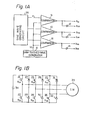
- an alternate current motcr (for example, an induction motor) 33 is driven by a power source through an inverter circuit consisting of the switching elements such as the transistors 21, 22, 23, 24, 25 and 26 and the rectifiers 27, 28, 29, 30, 31 and 32.
- the outputs of the signal generating circuit shown in FIG. lA are applied to the bases b 21 , b 22 , b 23 , b 24 , b 25 and b 26 of the transistors 21, 22, 23, 24, 25 and 26 shown in FIG. 1B, respectively.
- the signal generating circuit shown in FIG. lA consists of a sine wave generating circuit 35, a saw-toothed wave generating circuit 8, a plurality of comparators 9, 10 and 11, and a plurality of inverters 12, 13 and 14.
- the sine wave output ei with the frequency f of the sine wave generating circuit 35 and the saw-toothed wave output V c with the frequency f' of the saw-toothed wave generating circuit 8 are compared in the comparators 9, 10 and 11.
- the HIGH level output is produced from the comparator when V c ⁇ e i
- the LOW level output is produced from the comparator when V c > e..
- the comparator is producing a HIGH level output, the transistor which receives this HIGH level output from said comparator as the base signal is rendered an ON state.
- the voltage applied to the load of the motor is determined by the time duration in which the upper side transistor connected to the positive terminal of the power source and the lower side transistor connected to the negative terminal of the terminal are simultaneously rendered an ON state.
- the voltage applied to the motor changes linearly in accordance with the change of the ratio t/T, where t is a time duration in which the transistor is rendered an ON state and T is the chopper cyclic term. In the present invention, this relationship is utilized.
- the sine wave generating circuit consists of a voltage-to-frequency converter 2, a counter 3, a function generator 4 and a plurality of digital-to-analog converters 5, 6 and 7.
- a direct current signal 1 for commanding a frequency f is applied to the input of the voltage-to-frequency converter 2 and the function generator .
- a plurality of comparators 9, 10 and 11 receive the outputs of the digital-to-analog converters 5, 6 and 7 as the first inputs ard the output of a saw-toothed wave generating circuit 8 as the second inputs.
- the drivers 15, 17 and 19 which supply outputs to the bases b 21 , b 23 and b 25 of the transistors 21, 23 and 25 are connected to the outputs of the comparators 9, 10 and 11, respectively.
- the drivers 16, 18 and 20 which supply outputs to the bases b22 , b 24 and b 26 of the transistors 22, 24 and 26 are connected to the outputs of the comparators 9, 10 and 11 through the inverters 12, 13 and 14, respectively.
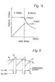
- a sine wave signal ei with the frequency f and a saw-toothed carrier wave signal V c with the frequency f' is compared by the comparator 9 and a pulse signal is obtained at the output of the comparator 9, as illustrated in the wave forms illustrated in FIG. 5.
- the peak value of the sine wave e . is varied in accordance with the frequency f by means of the function generator 4.
- the transistors in the circuit of FIG. lB are selectively caused to become conductive in accordance with the cut wave form as a result of the comparison between the signals e i and Vc by the comparators 9, 10 and 11.
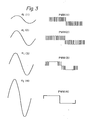
- FIG. 3 the wave forms of the sine wave signals e i (1), e i (2), e i (3) and e i (4) and the corresponding wave forms PWM (1), PWM (2), PWM (3) and PWM (4) of the output of the pulse width modulation inverter shown in FIG. 1B.
- This pulse width modulation inverter is driven by the signal generating circuit of FIG. 2.
- the sine wave signal is expressed as the wave form e i (1) or e i (2) having a relatively small amplitude, and the corresponding wave form of the output of the pulse width modulation inverter is expressed as PWM (1) or PWM (2), respectively.
- PWM (1) or PWM (2) the corresponding wave form of the output of the pulse width modulation inverter
- the sine wave signal is expressed as the wave form e i (3) or e i (4) having a relatively large amplitude, and the corresponding wave form of the output of the pulse width modulation inverter is expressed as PWM (3) or PWM (4), respectively.
- PWM (3) or PWM (4) the corresponding wave form of the output of the pulse width modulation inverter
- a smooth running of the motor in the low speed is ensured because of the application of the simulated sine wave voltage to the motor, and the rate of utilization of the power source for the motor in the high speed region is kept at a high level because of the application of the rectangular wave voltage.
- the transition of the motor runnirg between the A- and B-ranges are effected smoothly, and thus the continuous control over the entire range, including the A- and B- ranges, of the running of the motor is performed satisfactorily.
Landscapes
- Engineering & Computer Science (AREA)
- Power Engineering (AREA)
- Inverter Devices (AREA)
- Control Of Ac Motors In General (AREA)
Applications Claiming Priority (2)
| Application Number | Priority Date | Filing Date | Title |
|---|---|---|---|
| JP12273178A JPS5549996A (en) | 1978-10-06 | 1978-10-06 | Motor drive system using pulse width modulation inverter |
| JP122731/78 | 1978-10-06 |
Publications (2)
| Publication Number | Publication Date |
|---|---|
| EP0009783A1 true EP0009783A1 (de) | 1980-04-16 |
| EP0009783B1 EP0009783B1 (de) | 1983-03-02 |
Family
ID=14843181
Family Applications (1)
| Application Number | Title | Priority Date | Filing Date |
|---|---|---|---|
| EP79103708A Expired EP0009783B1 (de) | 1978-10-06 | 1979-09-28 | System zum Antrieb eines Motors mittels eines impulsbreiten modulierten Wechselrichters |
Country Status (4)
| Country | Link |
|---|---|
| US (1) | US4333042A (de) |
| EP (1) | EP0009783B1 (de) |
| JP (1) | JPS5549996A (de) |
| DE (1) | DE2964967D1 (de) |
Cited By (10)
| Publication number | Priority date | Publication date | Assignee | Title |
|---|---|---|---|---|
| EP0073504A1 (de) * | 1981-08-31 | 1983-03-09 | Kollmorgen Corporation | Steuersystem für Wechselstrom-Induktionsmotoren |
| DE3245761A1 (de) * | 1982-04-29 | 1984-02-23 | Brown, Boveri & Cie Ag, 6800 Mannheim | Verfahren zur steuerung des magnetischen flusses einer asynchronmaschine und einrichtung hierzu |
| GB2125239A (en) * | 1982-08-06 | 1984-02-29 | Ferranti Plc | A three phase supply synthesis arrangement |
| EP0089627A3 (de) * | 1982-03-18 | 1984-03-28 | Vee Arc Corporation | Asynchrongesteuerte Trägermodulation |
| GB2149242A (en) * | 1983-09-30 | 1985-06-05 | Matsushita Electric Industrial Co Ltd | Inverter controlling apparatus for induction motor drive |
| US4833586A (en) * | 1986-10-25 | 1989-05-23 | Hitachi, Ltd. | PWM control for power converter system utilizing pulse dropping at minimum pulse widths |
| WO2004073158A1 (en) * | 2003-02-06 | 2004-08-26 | Wavecrest Laboratories L.L.C. | Software-based adaptive control system for electric motors and generators |
| EP1622252A3 (de) * | 1998-05-28 | 2007-06-13 | Ibiden Co., Ltd. | Motorantriebsschaltung |
| AT510756A3 (de) * | 2010-11-16 | 2014-08-15 | Fachhochschule Technikum Wien | Pwm-modulator mit nichtlinearer umwandlungsfunktion |
| WO2019238296A1 (de) * | 2018-06-15 | 2019-12-19 | Robert Bosch Gmbh | Verfahren zum betreiben einer elektrischen maschine, steuergerät und elektrische maschine |
Families Citing this family (19)
| Publication number | Priority date | Publication date | Assignee | Title |
|---|---|---|---|---|
| US4377779A (en) * | 1980-12-29 | 1983-03-22 | General Electric Company | Pulse width modulated inverter machine drive |
| JPS58224572A (ja) * | 1982-06-24 | 1983-12-26 | Mitsubishi Electric Corp | パルス幅変調インバ−タ装置の電圧基準波形発生回路 |
| US4620143A (en) * | 1984-11-09 | 1986-10-28 | Westinghouse Electric Corp. | Digital pulse width modulation motor control system |
| US4651079A (en) * | 1985-11-29 | 1987-03-17 | Wills Frank E | Pulse width modulated inverter system for driving single phase a-c induction motor at a constant voltage/frequency ratio |
| US5252905A (en) * | 1985-12-23 | 1993-10-12 | York International Corporation | Driving system for single phase A-C induction motor |
| JPH0810994B2 (ja) * | 1986-02-18 | 1996-01-31 | 株式会社東芝 | インバ−タ装置 |
| US4920475A (en) * | 1988-03-07 | 1990-04-24 | California Institute Of Technology | Integrated traction inverter and battery charger apparatus |
| DE58908893D1 (de) * | 1988-03-21 | 1995-03-02 | Siemens Ag | Pulsumrichtergespeiste Drehfeldmaschine. |
| US4904919A (en) * | 1988-06-21 | 1990-02-27 | Allen-Bradley Company, Inc. | Dual mode control of a PWM motor drive for current limiting |
| US5583620A (en) * | 1990-03-23 | 1996-12-10 | Canon Kabushiki Kaisha | Image forming apparatus having scanner driven by pulse motor |
| JPH06102912A (ja) * | 1992-09-18 | 1994-04-15 | Fanuc Ltd | サーボアンプ及びサーボシステム |
| US5923133A (en) * | 1997-05-30 | 1999-07-13 | Stmicroelectronics, Inc. | Adaptive slew rate adjustment for a brushless multiphase DC motor and method |
| US6246207B1 (en) | 1998-06-26 | 2001-06-12 | A. O. Smith Corporation | Method and apparatus for controlling an induction motor |
| US6940242B1 (en) | 2003-01-29 | 2005-09-06 | Wavecrest Laboratories, Llc | Motor control system for dynamically changing motor energization current waveform profiles |
| EP1522141B1 (de) * | 2002-06-19 | 2007-11-14 | Wavecrest Laboratories, LLC | Motorsteuerungssystem und verfahren mit adaptivem stromverlauf |
| US7197390B2 (en) * | 2003-03-13 | 2007-03-27 | Wavecrest Laboratories Llc | Electric vehicle with adaptive cruise control system |
| US7312592B2 (en) * | 2004-04-26 | 2007-12-25 | Maslov Boris A | Adaptive system for optimizing excitation current waveform profiles for electric motors |
| GB2530293B (en) * | 2014-09-17 | 2017-08-02 | Nidec Control Techniques Ltd | Method of controlling a power output of an inverter drive |
| JP6404169B2 (ja) * | 2015-04-02 | 2018-10-10 | 株式会社神戸製鋼所 | 圧縮機ユニットおよびガス供給装置 |
Citations (4)
| Publication number | Priority date | Publication date | Assignee | Title |
|---|---|---|---|---|
| DE2109026A1 (de) * | 1971-02-25 | 1972-08-31 | Nippon Yusoki Co Ltd | Steuervorrichtung für einen bürstenlosen Motor eines Elektrofahrzeuges |
| US3971972A (en) * | 1975-03-14 | 1976-07-27 | Allis-Chalmers Corporation | Transistor inverter motor drive having voltage boost at low speeds |
| DE2610431A1 (de) * | 1975-03-14 | 1976-09-16 | Allis Chalmers | Motorantrieb mit transistor-brueckeninverter und reduzierten oberschwingungen |
| DE2752108A1 (de) * | 1976-12-06 | 1978-06-15 | Epitoegepgyarto Vallalat | Verfahren und schaltungsanordnung zum stromrichten, insbesondere zur kontinuierlichen drehzahlregelung von wechselstrommotoren |
Family Cites Families (7)
| Publication number | Priority date | Publication date | Assignee | Title |
|---|---|---|---|---|
| CH419326A (de) * | 1964-03-20 | 1966-08-31 | Bbc Brown Boveri & Cie | Frequenz- und amplitudenabhängiger Sollwertgeber |
| DE1488096C3 (de) * | 1964-04-24 | 1978-10-05 | Bbc Brown Boveri & Cie | Wechselrichterschaltung |
| JPS50139923A (de) * | 1974-04-26 | 1975-11-10 | ||
| HU172831B (hu) * | 1976-03-31 | 1978-12-28 | Egyt Gyogyszervegyeszeti Gyar | Sposob poluchenija kompleksov oligo- i poligalakturonnyk kislot s ionami zhiznenno vazhnykh metallov |
| JPS52154020A (en) * | 1976-06-17 | 1977-12-21 | Mitsubishi Electric Corp | Control system for induction motor by plurality of pulse duration modulated variable frequency inverter |
| US4227138A (en) * | 1978-04-10 | 1980-10-07 | General Electric Company | Reversible variable frequency oscillator for smooth reversing of AC motor drives |
| US4247890A (en) * | 1979-04-24 | 1981-01-27 | General Electric Company | Reversible inverter system having improved control scheme |
-
1978
- 1978-10-06 JP JP12273178A patent/JPS5549996A/ja active Pending
-
1979
- 1979-09-27 US US06/079,500 patent/US4333042A/en not_active Expired - Lifetime
- 1979-09-28 DE DE7979103708T patent/DE2964967D1/de not_active Expired
- 1979-09-28 EP EP79103708A patent/EP0009783B1/de not_active Expired
Patent Citations (4)
| Publication number | Priority date | Publication date | Assignee | Title |
|---|---|---|---|---|
| DE2109026A1 (de) * | 1971-02-25 | 1972-08-31 | Nippon Yusoki Co Ltd | Steuervorrichtung für einen bürstenlosen Motor eines Elektrofahrzeuges |
| US3971972A (en) * | 1975-03-14 | 1976-07-27 | Allis-Chalmers Corporation | Transistor inverter motor drive having voltage boost at low speeds |
| DE2610431A1 (de) * | 1975-03-14 | 1976-09-16 | Allis Chalmers | Motorantrieb mit transistor-brueckeninverter und reduzierten oberschwingungen |
| DE2752108A1 (de) * | 1976-12-06 | 1978-06-15 | Epitoegepgyarto Vallalat | Verfahren und schaltungsanordnung zum stromrichten, insbesondere zur kontinuierlichen drehzahlregelung von wechselstrommotoren |
Cited By (10)
| Publication number | Priority date | Publication date | Assignee | Title |
|---|---|---|---|---|
| EP0073504A1 (de) * | 1981-08-31 | 1983-03-09 | Kollmorgen Corporation | Steuersystem für Wechselstrom-Induktionsmotoren |
| EP0089627A3 (de) * | 1982-03-18 | 1984-03-28 | Vee Arc Corporation | Asynchrongesteuerte Trägermodulation |
| DE3245761A1 (de) * | 1982-04-29 | 1984-02-23 | Brown, Boveri & Cie Ag, 6800 Mannheim | Verfahren zur steuerung des magnetischen flusses einer asynchronmaschine und einrichtung hierzu |
| GB2125239A (en) * | 1982-08-06 | 1984-02-29 | Ferranti Plc | A three phase supply synthesis arrangement |
| GB2149242A (en) * | 1983-09-30 | 1985-06-05 | Matsushita Electric Industrial Co Ltd | Inverter controlling apparatus for induction motor drive |
| US4833586A (en) * | 1986-10-25 | 1989-05-23 | Hitachi, Ltd. | PWM control for power converter system utilizing pulse dropping at minimum pulse widths |
| EP1622252A3 (de) * | 1998-05-28 | 2007-06-13 | Ibiden Co., Ltd. | Motorantriebsschaltung |
| WO2004073158A1 (en) * | 2003-02-06 | 2004-08-26 | Wavecrest Laboratories L.L.C. | Software-based adaptive control system for electric motors and generators |
| AT510756A3 (de) * | 2010-11-16 | 2014-08-15 | Fachhochschule Technikum Wien | Pwm-modulator mit nichtlinearer umwandlungsfunktion |
| WO2019238296A1 (de) * | 2018-06-15 | 2019-12-19 | Robert Bosch Gmbh | Verfahren zum betreiben einer elektrischen maschine, steuergerät und elektrische maschine |
Also Published As
| Publication number | Publication date |
|---|---|
| JPS5549996A (en) | 1980-04-11 |
| US4333042A (en) | 1982-06-01 |
| EP0009783B1 (de) | 1983-03-02 |
| DE2964967D1 (en) | 1983-04-07 |
Similar Documents
| Publication | Publication Date | Title |
|---|---|---|
| EP0009783A1 (de) | System zum Antrieb eines Motors mittels eines impulsbreiten modulierten Wechselrichters | |
| US4691269A (en) | PWM inverter apparatus | |
| US4443841A (en) | Neutral-point-clamped PWM inverter | |
| EP0102614B1 (de) | Verfahren und Gerät zur Regelung eines pulsbreitenmodulierten Wechselrichters | |
| US4562393A (en) | Modulation scheme for PWM-type amplifiers or motors | |
| EP0430044A2 (de) | Verfahren zur Steuerung eines Wechselrichters | |
| US4295189A (en) | Apparatus and method for generating waveforms which are particularly suitable for a PWM-driven motor | |
| US4128793A (en) | Power circuit for variable frequency, variable magnitude power conditioning system | |
| JPS6373898A (ja) | インバ−タ装置 | |
| US4361866A (en) | Power converter apparatus | |
| US3958174A (en) | Modulated induction generator | |
| US5463300A (en) | AC motor controller with 180 degree conductive switches | |
| EP0065396A2 (de) | Gleichstrom-Wechselstrom-Umformer | |
| US4179727A (en) | Control device for a pulse-width modulated inverter | |
| GB1412380A (en) | Triangular-voltage generator | |
| US4599686A (en) | Method and apparatus for driving a transistorized polyphase pulse inverter | |
| EP0338833A3 (de) | Pulsbreitenmodulierungswechselrichtersteuereinheit | |
| Peak et al. | Transistorized PWM inverter-induction motor drive system | |
| KR830001119Y1 (ko) | 펄스폭 변조 인버터를 이용한 전동기 구동장치 | |
| IL38533A (en) | Speed controls for electric motors | |
| SU684704A1 (ru) | Способ управлени непосредственным преобразователем частоты | |
| SU584415A1 (ru) | Двухтактный инвертор | |
| JP2644255B2 (ja) | インバータの制御方法 | |
| SU788327A1 (ru) | Устройство дл регулировани частоты вращени трехфазного асинхронного электродвигател | |
| Thangaprakash et al. | Integrated control algorithm for an effective control of Z-source inverter using modified voltage space vector |
Legal Events
| Date | Code | Title | Description |
|---|---|---|---|
| PUAI | Public reference made under article 153(3) epc to a published international application that has entered the european phase |
Free format text: ORIGINAL CODE: 0009012 |
|
| 17P | Request for examination filed | ||
| AK | Designated contracting states |
Designated state(s): DE FR GB |
|
| GRAA | (expected) grant |
Free format text: ORIGINAL CODE: 0009210 |
|
| AK | Designated contracting states |
Designated state(s): DE FR GB |
|
| ET | Fr: translation filed | ||
| REF | Corresponds to: |
Ref document number: 2964967 Country of ref document: DE Date of ref document: 19830407 |
|
| PLBI | Opposition filed |
Free format text: ORIGINAL CODE: 0009260 |
|
| PLBI | Opposition filed |
Free format text: ORIGINAL CODE: 0009260 |
|
| 26 | Opposition filed |
Opponent name: DANFOSS A/S Effective date: 19831123 |
|
| 26 | Opposition filed |
Opponent name: LICENTIA PATENT-VERWALTUNGS-GMBH Effective date: 19831130 |
|
| PGFP | Annual fee paid to national office [announced via postgrant information from national office to epo] |
Ref country code: FR Payment date: 19840810 Year of fee payment: 6 |
|
| PGFP | Annual fee paid to national office [announced via postgrant information from national office to epo] |
Ref country code: DE Payment date: 19840928 Year of fee payment: 6 |
|
| PLBN | Opposition rejected |
Free format text: ORIGINAL CODE: 0009273 |
|
| STAA | Information on the status of an ep patent application or granted ep patent |
Free format text: STATUS: OPPOSITION REJECTED |
|
| 27O | Opposition rejected |
Effective date: 19860205 |
|
| PG25 | Lapsed in a contracting state [announced via postgrant information from national office to epo] |
Ref country code: FR Free format text: LAPSE BECAUSE OF NON-PAYMENT OF DUE FEES Effective date: 19880531 |
|
| PG25 | Lapsed in a contracting state [announced via postgrant information from national office to epo] |
Ref country code: DE Effective date: 19880601 |
|
| GBPC | Gb: european patent ceased through non-payment of renewal fee | ||
| REG | Reference to a national code |
Ref country code: FR Ref legal event code: ST |
|
| PG25 | Lapsed in a contracting state [announced via postgrant information from national office to epo] |
Ref country code: GB Free format text: LAPSE BECAUSE OF NON-PAYMENT OF DUE FEES Effective date: 19881118 |