EP0010053B1 - Konstruktionsverfahren für Bassins für die Nuklearindustrie, und nach diesem Verfahren hergestellte Bassins - Google Patents
Konstruktionsverfahren für Bassins für die Nuklearindustrie, und nach diesem Verfahren hergestellte Bassins Download PDFInfo
- Publication number
- EP0010053B1 EP0010053B1 EP19790420048 EP79420048A EP0010053B1 EP 0010053 B1 EP0010053 B1 EP 0010053B1 EP 19790420048 EP19790420048 EP 19790420048 EP 79420048 A EP79420048 A EP 79420048A EP 0010053 B1 EP0010053 B1 EP 0010053B1
- Authority
- EP
- European Patent Office
- Prior art keywords
- face
- panels
- section members
- tank
- concrete
- Prior art date
- Legal status (The legal status is an assumption and is not a legal conclusion. Google has not performed a legal analysis and makes no representation as to the accuracy of the status listed.)
- Expired
Links
- 238000000034 method Methods 0.000 title claims description 10
- 239000002184 metal Substances 0.000 claims description 14
- 230000009182 swimming Effects 0.000 claims description 9
- 238000009415 formwork Methods 0.000 claims description 8
- 230000002787 reinforcement Effects 0.000 claims description 7
- 239000004568 cement Substances 0.000 claims description 6
- 235000000396 iron Nutrition 0.000 claims description 5
- 230000000717 retained effect Effects 0.000 claims description 2
- 238000003466 welding Methods 0.000 claims description 2
- 239000010425 asbestos Substances 0.000 claims 1
- 239000000463 material Substances 0.000 claims 1
- 229910052895 riebeckite Inorganic materials 0.000 claims 1
- 238000009416 shuttering Methods 0.000 claims 1
- 239000011248 coating agent Substances 0.000 description 11
- 238000000576 coating method Methods 0.000 description 11
- 238000010276 construction Methods 0.000 description 6
- 239000007787 solid Substances 0.000 description 3
- 229910001220 stainless steel Inorganic materials 0.000 description 3
- 239000010935 stainless steel Substances 0.000 description 3
- 238000012795 verification Methods 0.000 description 3
- 239000000835 fiber Substances 0.000 description 2
- 241000135309 Processus Species 0.000 description 1
- 241001080024 Telles Species 0.000 description 1
- 240000008042 Zea mays Species 0.000 description 1
- 230000015556 catabolic process Effects 0.000 description 1
- 238000006731 degradation reaction Methods 0.000 description 1
- 231100001261 hazardous Toxicity 0.000 description 1
- 238000005304 joining Methods 0.000 description 1
- 230000014759 maintenance of location Effects 0.000 description 1
- 238000004519 manufacturing process Methods 0.000 description 1
- 239000004570 mortar (masonry) Substances 0.000 description 1
- 238000004080 punching Methods 0.000 description 1
- 239000000523 sample Substances 0.000 description 1
- 238000005507 spraying Methods 0.000 description 1
Images
Classifications
-
- E—FIXED CONSTRUCTIONS
- E04—BUILDING
- E04H—BUILDINGS OR LIKE STRUCTURES FOR PARTICULAR PURPOSES; SWIMMING OR SPLASH BATHS OR POOLS; MASTS; FENCING; TENTS OR CANOPIES, IN GENERAL
- E04H7/00—Construction or assembling of bulk storage containers employing civil engineering techniques in situ or off the site
- E04H7/02—Containers for fluids or gases; Supports therefor
- E04H7/18—Containers for fluids or gases; Supports therefor mainly of concrete, e.g. reinforced concrete, or other stone-like material
Definitions
- the present invention relates to the process for constructing enclosures or swimming pools used in the nuclear industry and to the swimming pool obtained according to this process in accordance with the preambles of claims 1 and 4.
- swimming pools of this kind are formed by a massive concrete polygonal profile whose vertical wall facing inward is covered by a metal coating, usually consisting of an assembly of stainless steel sheets.
- This coating must obviously have a perfect seal and homogeneity, so that it has proved essential to carry out the radiographic verification of the welds for joining the sheets, this verification having to take place both immediately after construction of the pool and periodically during the use thereof.
- French patent application No. 2 383 289 proposed to carry out the assembly welds of the sheets of the coating at the level of hollow metal profiles arranged vertically so that their face turned towards the he interior of the swimming pool is at the level of the concrete wall intended to form a support for the aforementioned coating.
- the support surface is thus preserved in its entirety and the interior space delimited by each profile can receive an X-ray film engaged by the upper end of the profile considered, which film is capable of cooperating with a source or probe lowered into the pool. .
- the present invention aims to remedy the aforementioned drawbacks of the prior art and to allow the simple and economical construction of a swimming pool for the nuclear industry of the aforementioned type, that is to say in which the internal metallic coating is applied against a bearing face interrupted by vertical metal sections provided hollow.
- the invention essentially consists, according to the characterizing parts of claims 1 and 4, of constituting the bearing face by superimposition on edge of rigid plates of cement or fiber cement with smooth walls, the superimposed plates being retained by projecting lateral fins provided facing each other on the vertical sections so as to behave in the manner of a lost formwork for pouring the concrete mass intended for filling the empty space formed between the solid and the superposition cited above.
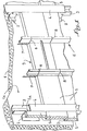
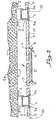
- the reference 1 designates the vertical wall of the concrete block, the face la of this wall being set back with respect to the dimension provided for the swimming pool, by a distance which can vary to a large extent and which in this case will assume to be of the order of 60 to 100 mm.
- a distance which can vary to a large extent and which in this case will assume to be of the order of 60 to 100 mm.
- a pair of irons 2 Across the side there are, in the usual way, referred to regular horizontal spacings, superimposed pairs 2 of vertical angle irons, fixed in place in any suitable manner, for example using sealed bolts or the like; each pair of irons 2 embraces a vertical profile 3 with a U-shaped cross section which opens towards the interior of the pool, that is to say opposite to the face 1 a.
- Each of the sections 3, assembled to the irons 2 by welding or otherwise, is closed by a vertical strip 4 made of stainless steel to form a hollow section.
- Such an assembly corresponds to the conventional construction in terms of swimming pools for the nuclear industry, for example according to French patent application No. 2 383 289 and therefore does not require a more detailed description.
- each slat 4 is established at a width slightly greater than that of the profile 3 which supports it, so as to thus determine two fins which project laterally with respect to said profile 3.
- the protruding fins, turned in the direction of one another, two contiguous slats 4 constitute a kind of clean vertical slide ensuring the retention of a series of superimposed plates 5, made of cement or, advantageously, of fiber cement.
- the vertical edges of these plates 5 are milled at 5a over a width equal to that of the fins projecting from the slats 4, so that the outer wall of said plates is at the same level as the free face of the aforementioned slats.
- these plates 5 constitute a formwork which determines, with the face 1a of the block 1, a free space referenced 9 in FIG. 2.
- the space 9 then has a relatively reduced height and it is easy under these conditions to operate the lining by introducing an appropriate amount of mortar or concrete, for example using a simple pump. After the mass thus injected has hardened, the operation is repeated, in the sense that a suitable number of plates 5 are again superimposed and that the new space 9 thus formed is filled with concrete.
- the reinforcement ladder 6 is dismantled after sectioning the fasteners 8.
- the plates 5 obviously remain incorporated in the assembly obtained, comprising it in the manner of a lost formwork.
- the value of this formwork can be considered negligible, especially if we take into account that its surface is presented in an absolutely smooth manner, without requiring any finishing work.
- the stainless steel sheets shown diagrammatically at 10 in FIG. 2, can bear against the plates 5 without any risk of deformation or of punching, in the same way, so that at the level of the vertical slats 4 associated with the profiles 3.
Landscapes
- Engineering & Computer Science (AREA)
- Architecture (AREA)
- General Engineering & Computer Science (AREA)
- Civil Engineering (AREA)
- Structural Engineering (AREA)
- On-Site Construction Work That Accompanies The Preparation And Application Of Concrete (AREA)
- Forms Removed On Construction Sites Or Auxiliary Members Thereof (AREA)
- Filling Or Discharging Of Gas Storage Vessels (AREA)
Claims (6)
Applications Claiming Priority (2)
| Application Number | Priority Date | Filing Date | Title |
|---|---|---|---|
| FR7829596 | 1978-10-11 | ||
| FR7829596A FR2438896A1 (fr) | 1978-10-11 | 1978-10-11 | Perfectionnements a la construction de piscines pour l'industrie nucleaire et applications analogues |
Publications (2)
| Publication Number | Publication Date |
|---|---|
| EP0010053A1 EP0010053A1 (de) | 1980-04-16 |
| EP0010053B1 true EP0010053B1 (de) | 1982-10-20 |
Family
ID=9213852
Family Applications (1)
| Application Number | Title | Priority Date | Filing Date |
|---|---|---|---|
| EP19790420048 Expired EP0010053B1 (de) | 1978-10-11 | 1979-10-11 | Konstruktionsverfahren für Bassins für die Nuklearindustrie, und nach diesem Verfahren hergestellte Bassins |
Country Status (4)
| Country | Link |
|---|---|
| EP (1) | EP0010053B1 (de) |
| DE (1) | DE2963896D1 (de) |
| ES (1) | ES484888A0 (de) |
| FR (1) | FR2438896A1 (de) |
Families Citing this family (6)
| Publication number | Priority date | Publication date | Assignee | Title |
|---|---|---|---|---|
| EP2152460B1 (de) * | 2007-05-04 | 2013-03-13 | Societat d'Obres i Treballs Subterranis del Pirineu (SOTS, S.L.) | Verfahren zur herstellung eines futters für ein becken, einen tank oder ein containergehäuse |
| FR2915695B1 (fr) * | 2007-05-04 | 2009-07-03 | Societat D Orbres I Freballs S | Realisation d'un cuvelage pour une piscine de refrigeration |
| FR2970889B1 (fr) * | 2011-02-02 | 2013-02-22 | Soc Dobres I Treballs Subterranis Del Pirineu Sots S L | Realisation d'un cuvelage pour piscine, bache ou enceinte de confinement ameliore |
| FR3020713A1 (fr) * | 2014-04-30 | 2015-11-06 | Eiffage Tp | Structure modulaire de renforcement de l'etancheite a l'air d'enceinte de confinement, modules constitutifs de cette structure, leur procede de mise en place et de demontage |
| CN113089777B (zh) * | 2021-03-26 | 2022-07-12 | 中广核工程有限公司 | 模块化环形混凝土不锈钢水箱及其施工方法 |
| FR3129024B1 (fr) * | 2021-11-05 | 2024-05-10 | Fives Nordon | Méthode d’assemblage d’un ensemble d’étanchéification d’une piscine d’installation nucléaire et un ensemble d’étanchéification d’une piscine d’installation nucléaire |
Family Cites Families (3)
| Publication number | Priority date | Publication date | Assignee | Title |
|---|---|---|---|---|
| US3404500A (en) * | 1965-06-03 | 1968-10-08 | Ishikawajima Harima Heavy Ind | Segmented metal lined liquid storing underground tank |
| FR1590183A (de) * | 1968-10-04 | 1970-04-13 | ||
| FR2383289A1 (fr) * | 1977-03-09 | 1978-10-06 | Commissariat Energie Atomique | Procede de realisation d'un revetement metallique radiographiable |
-
1978
- 1978-10-11 FR FR7829596A patent/FR2438896A1/fr active Granted
-
1979
- 1979-10-10 ES ES484888A patent/ES484888A0/es active Granted
- 1979-10-11 DE DE7979420048T patent/DE2963896D1/de not_active Expired
- 1979-10-11 EP EP19790420048 patent/EP0010053B1/de not_active Expired
Also Published As
| Publication number | Publication date |
|---|---|
| FR2438896A1 (fr) | 1980-05-09 |
| FR2438896B1 (de) | 1983-01-07 |
| ES8100409A1 (es) | 1980-11-01 |
| ES484888A0 (es) | 1980-11-01 |
| EP0010053A1 (de) | 1980-04-16 |
| DE2963896D1 (en) | 1982-11-25 |
Similar Documents
| Publication | Publication Date | Title |
|---|---|---|
| EP0010053B1 (de) | Konstruktionsverfahren für Bassins für die Nuklearindustrie, und nach diesem Verfahren hergestellte Bassins | |
| CA2691934A1 (fr) | Element de construction arme | |
| FR2523627A1 (fr) | Procede pour conforter des arches ou des constructions analogues | |
| WO1985003966A1 (fr) | Elements de structure et procede de realisation | |
| FR2544005A1 (fr) | Methode pour la construction d'une piscine realisee avec des elements de coffrage perdus | |
| EP0077579B1 (de) | Schalung aus zusammengesetzten Elementen zum Giessen von Beton | |
| FR2613394A1 (fr) | Parois etanches pour ouvrages hydrauliques en beton compact et procede de construction de celles-ci | |
| FR1465570A (fr) | Panneau d'armature creux préfabriqué, à parois coffrantes minces, armées et entretoisées, pour la réalisation d'éléments de construction | |
| EP2563975B1 (de) | Formteilwand mit fertigteilverkleidung | |
| FR2724680A1 (fr) | Perfectionnements a un panneau formant coffrage perdu pour la construction d'ouvrages de genie civil, et notamment de piscines, et procede de mise en oeuvre de ces panneaux | |
| BE1015453A3 (fr) | Procede de realisation de surfaces en beton et joint utilise a cet effet. | |
| EP0094465B1 (de) | Verfahren zur Herstellung von Konstruktionsplatten hergestellte Platten und Vorrichtung zur Ausführung des Verfahrens | |
| FR2473085A1 (fr) | Procede pour assurer la continuite des armatures entre des panneaux successifs d'une paroi en beton arme, et panier d'armatures pour la mise en oeuvre de ce procede | |
| FR2704253A1 (fr) | Procédé de construction de bâtiments à ossature de béton armé. | |
| WO1996003552A1 (fr) | Conduit souterrain | |
| FR2759106A1 (fr) | Procede de realisation simultanee de deux parois en beton separees par un espace vide | |
| FR2878877A1 (fr) | Bloc de coffrage | |
| WO2007079989A1 (fr) | Panneau pour coffrage | |
| FR2650020A1 (fr) | Moellon pour la construction de parois verticales en beton arme, en particulier de parois de piscines, et son procede d'utilisation | |
| CA2110902A1 (fr) | Enceinte allongee de grande section et son procede de realisation | |
| FR2490540A1 (fr) | Procede pour la realisation de parois moulees armees et caissons pour sa mise en oeuvre | |
| FR2955602A1 (fr) | Procede pour realiser des ouvrages de genie civil, tel qu'une piscine ou un bassin de retenue d'eau | |
| FR2805555A1 (fr) | Coffrage perdus alveolaires pour la construction de murs et de planchers et procedes de fabrication et de mise en oeuvre desdits coffrages | |
| FR2657639A1 (fr) | Procede de coffrage d'une paroi en beton arme moulee dans une tranchee et coffrage pour la mise en óoeuvre de ce procede. | |
| FR2465038A1 (fr) | Enveloppe et procede de formation de couches isolantes d'assise |
Legal Events
| Date | Code | Title | Description |
|---|---|---|---|
| PUAI | Public reference made under article 153(3) epc to a published international application that has entered the european phase |
Free format text: ORIGINAL CODE: 0009012 |
|
| AK | Designated contracting states |
Designated state(s): BE DE GB IT NL |
|
| 17P | Request for examination filed | ||
| ITF | It: translation for a ep patent filed | ||
| GRAA | (expected) grant |
Free format text: ORIGINAL CODE: 0009210 |
|
| AK | Designated contracting states |
Designated state(s): BE DE GB IT NL |
|
| REF | Corresponds to: |
Ref document number: 2963896 Country of ref document: DE Date of ref document: 19821125 |
|
| ITTA | It: last paid annual fee | ||
| PGFP | Annual fee paid to national office [announced via postgrant information from national office to epo] |
Ref country code: BE Payment date: 19930928 Year of fee payment: 15 |
|
| PGFP | Annual fee paid to national office [announced via postgrant information from national office to epo] |
Ref country code: GB Payment date: 19931001 Year of fee payment: 15 |
|
| PGFP | Annual fee paid to national office [announced via postgrant information from national office to epo] |
Ref country code: NL Payment date: 19931031 Year of fee payment: 15 |
|
| PGFP | Annual fee paid to national office [announced via postgrant information from national office to epo] |
Ref country code: DE Payment date: 19931130 Year of fee payment: 15 |
|
| PG25 | Lapsed in a contracting state [announced via postgrant information from national office to epo] |
Ref country code: GB Effective date: 19941011 |
|
| PG25 | Lapsed in a contracting state [announced via postgrant information from national office to epo] |
Ref country code: BE Effective date: 19941031 |
|
| BERE | Be: lapsed |
Owner name: KOPIAN DIMITRI Effective date: 19941031 |
|
| PG25 | Lapsed in a contracting state [announced via postgrant information from national office to epo] |
Ref country code: NL Effective date: 19950501 |
|
| GBPC | Gb: european patent ceased through non-payment of renewal fee |
Effective date: 19941011 |
|
| NLV4 | Nl: lapsed or anulled due to non-payment of the annual fee | ||
| PG25 | Lapsed in a contracting state [announced via postgrant information from national office to epo] |
Ref country code: DE Effective date: 19950701 |
|
| PLBE | No opposition filed within time limit |
Free format text: ORIGINAL CODE: 0009261 |
|
| STAA | Information on the status of an ep patent application or granted ep patent |
Free format text: STATUS: NO OPPOSITION FILED WITHIN TIME LIMIT |