EP2152460B1 - Verfahren zur herstellung eines futters für ein becken, einen tank oder ein containergehäuse - Google Patents
Verfahren zur herstellung eines futters für ein becken, einen tank oder ein containergehäuse Download PDFInfo
- Publication number
- EP2152460B1 EP2152460B1 EP08805529A EP08805529A EP2152460B1 EP 2152460 B1 EP2152460 B1 EP 2152460B1 EP 08805529 A EP08805529 A EP 08805529A EP 08805529 A EP08805529 A EP 08805529A EP 2152460 B1 EP2152460 B1 EP 2152460B1
- Authority
- EP
- European Patent Office
- Prior art keywords
- sheets
- welding
- wall
- concrete
- adjacent
- Prior art date
- Legal status (The legal status is an assumption and is not a legal conclusion. Google has not performed a legal analysis and makes no representation as to the accuracy of the status listed.)
- Active
Links
Images









Classifications
-
- B—PERFORMING OPERATIONS; TRANSPORTING
- B23—MACHINE TOOLS; METAL-WORKING NOT OTHERWISE PROVIDED FOR
- B23K—SOLDERING OR UNSOLDERING; WELDING; CLADDING OR PLATING BY SOLDERING OR WELDING; CUTTING BY APPLYING HEAT LOCALLY, e.g. FLAME CUTTING; WORKING BY LASER BEAM
- B23K9/00—Arc welding or cutting
- B23K9/02—Seam welding; Backing means; Inserts
- B23K9/035—Seam welding; Backing means; Inserts with backing means disposed under the seam
- B23K9/0352—Seam welding; Backing means; Inserts with backing means disposed under the seam the backing means being movable during the welding operation
-
- E—FIXED CONSTRUCTIONS
- E04—BUILDING
- E04H—BUILDINGS OR LIKE STRUCTURES FOR PARTICULAR PURPOSES; SWIMMING OR SPLASH BATHS OR POOLS; MASTS; FENCING; TENTS OR CANOPIES, IN GENERAL
- E04H4/00—Swimming or splash baths or pools
- E04H4/0075—Swimming or splash baths or pools made of concrete
- E04H4/0081—Swimming or splash baths or pools made of concrete with walls and floor cast in situ
-
- G—PHYSICS
- G21—NUCLEAR PHYSICS; NUCLEAR ENGINEERING
- G21C—NUCLEAR REACTORS
- G21C19/00—Arrangements for treating, for handling, or for facilitating the handling of, fuel or other materials which are used within the reactor, e.g. within its pressure vessel
- G21C19/02—Details of handling arrangements
- G21C19/06—Magazines for holding fuel elements or control elements
- G21C19/07—Storage racks; Storage pools
-
- Y—GENERAL TAGGING OF NEW TECHNOLOGICAL DEVELOPMENTS; GENERAL TAGGING OF CROSS-SECTIONAL TECHNOLOGIES SPANNING OVER SEVERAL SECTIONS OF THE IPC; TECHNICAL SUBJECTS COVERED BY FORMER USPC CROSS-REFERENCE ART COLLECTIONS [XRACs] AND DIGESTS
- Y10—TECHNICAL SUBJECTS COVERED BY FORMER USPC
- Y10T—TECHNICAL SUBJECTS COVERED BY FORMER US CLASSIFICATION
- Y10T29/00—Metal working
- Y10T29/49—Method of mechanical manufacture
- Y10T29/49826—Assembling or joining
- Y10T29/49947—Assembling or joining by applying separate fastener
- Y10T29/49966—Assembling or joining by applying separate fastener with supplemental joining
- Y10T29/49968—Metal fusion joining
Definitions
- the invention relates to a method for producing a casing for a swimming pool, tarpaulin or containment enclosure, in particular a confinement enclosure of a nuclear power plant, comprising at least the assembly of a series of adjacent sheets and the welding plates to each other to form a portion of a surface of the casing by producing a weld bead.
- the casing of a swimming pool, enclosure or containment cover consists of an inner metal coating attached to a concrete structure, so as to confine the effluents and to guarantee the watertightness of the pool in normal operation. or accidental.
- the metal coating consists of sheets welded to each other.
- the welding is performed by a welding technique employing a batten disposed at the rear of the sheets, at the area to be welded.
- a welding technique employing a batten disposed at the rear of the sheets, at the area to be welded.
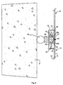
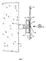
- two adjacent metal sheets 1 and 2 were welded by the lattice welding technique.
- the sheets 1 and 2 are thus fixed on a concrete wall 3.
- An anchoring element 4 embedded in the concrete is secured to a slat 5 disposed in the concrete and resting at the level of the weld zone 6 against the sheets 1 and 2.
- a concrete 10 said concrete second phase is then disposed between the wall 3 and the plates 1 and 2 and it encloses a first enclosure 9 fixed to the concrete wall 3.
- This first enclosure 9 has a bottom wall 9a integral with the concrete wall 3 (first phase concrete) and side walls 9b coming into contact with them. sheets 1 and 2.
- the first enclosure 9 has a U-shaped section.
- a second enclosure 11 having dimensions smaller than those of the first enclosure is disposed in the space formed in the first enclosure 9. It comprises an upper wall 11a coming into contact with the sheets 1 and 2, at the welding zone 6.
- the upper wall 11a is extended by side walls 11b bearing and secured to the bottom wall 9a of the first chamber 9.
- the second enclosure 11 On the figure 2 the second enclosure 11 has an inverted U-shaped section.
- the space formed between the side walls 9b and 11b is thus the channel 8 for recovering drips in case of leakage at the weld zone.
- the upper wall 11a corresponds to the slat 5 shown on the figure 1 .
- the patent application EP-A-0191672 describes such an embodiment.
- the object of the invention is a method of producing a casing for a swimming pool, tarpaulin or containment enclosure that overcomes the drawbacks of the prior art. More particularly, the object of the invention is to provide a method of guaranteeing the sealing of the welds produced and the mechanical strength of the casing.
- the casing of a swimming pool, a tarpaulin or a containment enclosure is made by successively rising side by side series of adjacent sheets and welding said sheets, so as to coat all the concrete walls of said swimming pool.
- each sheet has on the face disposed opposite the concrete wall anchoring elements ensuring the mechanical strength of the casing. These anchoring elements are completely independent of the weld zones, once the concrete is poured. Thus, they are not connected to the weld zones.
- the adjacent sheets are welded by a weld or a butt weld (or edge to edge) fully penetrated.
- Fully penetrated butt weld means the production of a weld bead joining the edges of two adjacent sheets, the two edges being generally separated from each other by a predetermined interval that the bead of solder fully fills.
- the fully penetrated butt weld does not require the use of a slat or a bearing surface as in the prior art. This makes it possible to obtain a weld bead having no junction defect and without risk of breakage due to bending stresses caused by a slat or a bearing surface.
- a rail is put in place at the right of the area to be welded.
- Such a rail makes it possible at least to carry out the checks of the casing joints and in particular the X-ray checks.
- a first particular embodiment of such a casing is, more particularly, illustrated on the Figures 3 to 6 .
- the two opposite faces 13 and 14 are connected by edges.
- the edges of the metal sheets 12 may have different shapes.
- the edges of a metal sheet 12 generally comprise two parts: a first part in contact with the first face 13 and a second part in contact with the second face 14.
- the first part advantageously forms a right angle with the first face 13 while the second part is a beveled part.
- the beveled portion of a sheet forms, preferably, an angle of 60 ° with the beveled portion of an adjacent sheet.
- an edge of a sheet 6 mm thick may comprise a bevelled portion of a thickness of 4 mm, with an inclination of about 30 ° relative to the first portion of said edge.
- the inclinations of the bevelled portions of two adjacent sheets, relative to the rest of their edge, are advantageously identical. This is not the case for sheets to be welded cornice. Indeed, for a cornice weld, the second parts (beveled portions) of two adjacent sheets respectively form an angle of 15 ° and an angle of 45 ° with the second portions of the associated edges.
- the first face 13 of each sheet 12 comprises, over its entire periphery, L-shaped angles 15.
- the angles 15 are, in fact, constituted by first and second substantially perpendicular wings .
- the first wing of an angle 15 is fixed to the first face 13 of the sheet 12, so as to be substantially perpendicular to said first face and near an edge of the sheet 12. More particularly, as shown on the side view of the figure 3 , the position of the angle 15 and the length of the second wing (wing parallel to the first face 13) are determined, so that said second wing does not extend beyond the first face 13.
- the first face 13 of each sheet also comprises anchoring elements 16 ensuring in particular the mechanical strength of the casing.
- anchoring elements 16 formed by profiles having a U-shaped section, are welded to the first face 13 of the sheet.
- the three anchoring elements 16 are arranged parallel to each other, in the width direction of the sheet 12. Notches are formed in the side walls of the anchoring elements 16, that is to say in the wings of each U, to place and point thin blades or dishes 16a.
- the welds 16b made to fix the anchoring elements 16 on the first face 13 of each sheet 12 may be inspected by bleeding in the workshop.
- the welds 16a are discontinuous. They could, however, be continuous.
- a series of sheets 12 is then mounted and fixed on a concrete wall 3 to form a portion of a wall of the casing.
- the sheets 12 are arranged successively side by side, with a predetermined pitch between two sheets 12.
- the pitch is, for example 2mm.
- the sheets are then fixed parallel to the concrete wall 3 at a predetermined distance.
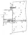
- the figure 4 illustrates a particular method of fixing a series of adjacent sheets 12 on a concrete wall 3.
- a sheet 12 is fixed to the concrete wall 3, via certain anchoring elements 16.
- anchoring elements 16 of two sheets 12 are, in fact, successively fastened to HALFEN type rails 17 embedded in the concrete wall 3.
- the fixing is carried out by by means of threaded rods 18, each fixed at one end to a HALFEN type rail 17 and at another end to a support plate 19, welded to an anchoring element 16.
- the sheets 12 then rest on expectations 20 protruding from the concrete wall 3.
- Each sheet 12 is, for example, moved using a suction bar 21 until some anchoring elements 16 each bear against support plates 19 previously fixed to the HALFEN rails 17 Once the sheet 12 is resting against the plates 19, its position is adjusted vertically and horizontally according to the adjacent plates 12. This adjustment allows, for example, to obtain the predetermined pitch between two adjacent sheets. Then, the anchoring elements 16 resting against the support plates 19 are welded to said plates 19. The welds thus produced can then be checked on site, for example by bleeding.
- the rail 22 comprises side walls and a bottom, formed by the first and second wings of the angles 15 of the two adjacent sheets and defining with the first faces of the two adjacent sheets, a free space to the right of the area to be welded.
- the space delimited by such a rail 22 and the first faces of the two sheets is, more particularly, intended to receive a mobile sled, during the realization of the weld.
- mobile sled means a mechanical assembly able to move in a controlled manner in the rail 22.
- a movable stretcher 24 is placed in the rail 22. It is held in the rail 22, against the first faces 13 of the sheets 12, by means of a support element bearing between the concrete wall 3 and 24.
- the support element is, for example, constituted by a pneumatic cylinder 25 bearing against the concrete wall 3.
- a thermal protection element 26 may also be disposed between said cylinder 25 and the stretcher 24.
- the stretcher 24 is intended to form a zone or an atmosphere of inert gas, at the region to be welded, on the side of the first faces 13 of the plates 12.
- the stretcher 24 being mobile, its movement follows the movement of the apparatus to solder, so as to always form the zone of inert gas at the place and at the moment when the welding is carried out.
- the lagoon 24 therefore comprises a neutral gas diffusion volume coming into contact with the two adjacent plates 12.
- the gas diffusion volume neutral is maintained in the rail 22 by a support plate 27, for adjusting the altitude of the diffusion volume and the slide in the rail 22.
- the diffusion volume is, more particularly, formed by a chute 28 maintained in abutment, by the pneumatic cylinder 25, on the two sheets 12.
- a seal 29 is advantageously disposed between the sheets 12 and said chute so as to make it tight.
- an inert gas diffuser 30 having a neutral gas injection tube 30a and outlet ports 30b is provided, possibly with stainless steel straw (not shown in FIG. figure 5 ), in the space provided by the chute 28.
- a ceramic plate 31 is disposed in the trough 28, between the diffuser 30 and the first faces 13 of the plates 12.
- Said plate 31 advantageously comprises a surface provided with a groove bearing against the first faces 13 (no represented on the figure 5 ).
- Said groove is disposed facing the zone to be welded and is intended to precisely locate the inert gas at the area to be welded.
- the weld bead 32 is then made on the side of the second faces 14, with the aid of a welding apparatus such as a welding apparatus of MIG or TIG type. A drip weld could also be done.
- the ceramic plate 31 is not necessary.
- any type of welding process can be used as long as it allows for a fully penetrated butt weld.
- the welding process can also be plasma, laser or electron beam welding.
- the X-ray control test is, as shown in FIG. figure 6 , made by placing a radiographic film 33 against the first faces 13 of the plates 12.
- the film 33 is disposed in the rail 22, at the welded zone (or weld bead 32) to be controlled.
- the film is held against the first faces 13 by the pneumatic cylinder 26 and a shim 34.
- the pneumatic cylinder 26 bears between the wall 3 and said shim 34.
- the film 33 can be arranged on a support plate 35 arranged in the rail 22.
- X-rays 36 are then applied at the weld bead 32, so as to transpose the weld on the radiographic film 33 and determine if it has defects.
- concrete also called concrete second phase
- concrete is poured between the concrete wall 3 and said welded sheets 12, in order to fill the space existing between said wall 3 and the plates 12.
- the anchoring elements 16 as well as the angles 15 are then embedded in said concrete, thus ensuring the mechanical strength of the part of the wall of the casing made.
- said anchoring elements 16 and the angles 15 are not in direct contact with the weld seams 32. This makes it possible to dissociate the sealing function provided by the weld seams 32 and the mechanical holding function ensured by the sealing elements. anchor 16 and angles 15.
- a production method according to the invention then makes it possible to obtain a weld having the quality and more particularly the mechanical characteristics of the metal sheets. This has the advantage of not having to take into account the particular characteristics of the welds during resistance calculations.
- the welded sheets serve, moreover, formwork for pouring concrete second phase between the concrete wall 3 and said sheets 12. This also improves the contact between the sheets 12 and said concrete.
- the anchoring elements may be made of ferritic steel because they are embedded in the second phase concrete.
- the welding operation being carried out in an inert gas atmosphere, this makes it possible to obtain welds of very good quality, in accordance with the requirements of the security code in force in the field of nuclear power plants.
- the weld checks can be carried out while the casing is being made. The sealing of the casing can then be guaranteed.
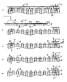
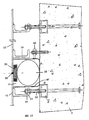
- the second embodiment of the Figures 7 to 13 represents the different phases of realization of a casing with butt welded sheets, and with a dripping recovery trough.
- the process used is similar to that of Figures 3 to 6 but the L-shaped angles 15 of the plates 12 are replaced by a dripping recovery trough 40 at the right of the weld bead 32.
- the same reference numbers will be used later to designate parts identical to those of the Figures 3 to 6 .
- the U-shaped anchoring element 16 of a first metal sheet 12 is fastened to the threaded rod 18 by means of an adjusting nut 41 and a counter-nut 42.
- the opposite end of the rod 18 is subject in an anchor 17 of the Halfen rail type embedded in the concrete 3 of the first phase.
- the adjustment nut 41 makes it possible to adjust the distance between the upper face of the concrete 3 and the sheet 12.
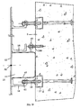
- the figure 8 shows the establishment of a chute 40 of dripping recovery.
- the chute 40 has a U-shape resting on the concrete 3, and one of the parallel branches extends perpendicular to the sheet 12 set back from the anchoring element 16.
- the parallel branches of the chute 40 and the bottom of said trough 40 delimit, with the first faces of the adjacent plates, a space to the right of the area to be welded.
- the chute 40 is held in place by means of a fixing lug 43 mounted in an adjustable manner on a threaded rod 18A anchored in the concrete 3.
- the fixing means of the chute 40 on the concrete wall 3 are completely independent anchoring elements 16.
- the chute 40 constitutes a rail, such as that delimited in the first embodiment by the L-shaped brackets.
- a second sheet 12 is positioned end to end in the same plane with the first sheet 12, followed by the introduction of a docking bar 44 opposite the chute 40.
- the zone to be welded of the two sheets 12 is equidistant from the parallel branches of the chute 40.
- the figure 11 illustrates the establishment of the mobile stretcher 24 held inside the trough 40 against the plates 12 via a support member bearing between the concrete wall 3 and the stretcher 24.
- the support element is, for example, constituted by a pneumatic jack 25 or an inflatable bead, bearing against the concrete wall 3.
- the figure 12 shows the welding phase of the two sheets 12.
- the presence of the dripping recovery trough 40 is an additional safety which guarantees the reliability of the sealing of the casing. It can also make it possible to produce the weld bead 32, using the mobile stretcher 24. In this case, it forms the rail 22.
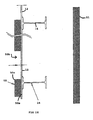
- the third embodiment of the Figures 14 to 21 represents the different phases of realization of a casing for swimming pool or containment cover, in a single phase of concreting.
- the same reference numbers will be used later to designate parts identical to those of Figures 3 to 13 .
- the sheets 12 are not attached to a concrete wall 3, but to one of the two walls 50 and 51, generally metal, a previously installed formwork .
- the distance separating the two walls 50 and 51 determines the thickness of the portion of the casing made.
- the figure 14 represents two adjacent plates 12 arranged and fixed on one of the faces 50a of the wall 50.
- the sheets 12 are arranged side by side and their adjacent edges define the area to be welded.
- the sheets 12 are disposed opposite the other wall 51 of the formwork.
- the anchoring elements 16 of the sheets 12 then protrude towards said wall 51.
- the wall 50 receiving the sheets 12 also has an opening 50b allowing access, by the face 50c of the wall 50, to the zone to be welded and therefore to achieve, as shown in FIG. figure 15 , the weld bead 32.
- the weld bead 32 is advantageously made by the face 50c of the wall 50 (that is to say on the left side with respect to the wall 50 on the figures 14 and 15 ) while the plates 12 are arranged on the face 50a of the wall 50 (that is to say on the right side with respect to the wall 50 on the figures 14 and 15 ).
- the solder is then controlled.
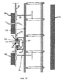
- a reinforcement 52 is disposed between the sheets 12 and the wall 51 and a dripping recovery trough 40 is disposed between the sheets 12 and said reinforcement, at the right of the weld bead 32.
- the dripping recovery trough 40 has a U-shaped and has parallel branches extending perpendicular to the two adjacent sheets 12. It thus takes support on the reinforcement 52.
- the weld bead 32 of the sheets 12 is preferably equidistant parallel branches of the chute 40.
- a seal 53 is then placed in the dripping recovery chute 40.
- the seal 53 ensures, by the activation of a pressurizing system 54, the sealing between the sheets 12 and the chute 40 and, more particularly, the end of the branches of the chute 40, in particular when there is a clearance 55 between the branches of the chute 40 and the sheets 12.
- the seal 53 is, in particular, consisting of a flexible blade 56 substantially curved in a rest position.
- the blade is provided at each of its ends with a rubber pad 57.
- the seal 53 is, thus, installed in the dripping recovery trough 40 in its rest position ( figure 17 ), by placing each pad 57 against a plate 12, on either side of the weld bead 32.
- the weld bead 32 is advantageously equidistant from the pads 57.
- the seal 53 flattens and the pads 57 are pressed against the plates 12 and obstruct the free space between the plates 12 and the branches of the chute 40 The pads 57 thus ensure the seal between the chute 40 and the plates 12, compensating the clearance 55.
- the dimensions of the blade 56 and the pads 57 are, more particularly, chosen to ensure the seal between the chute 40 and the sheets 12, when the blade is flattened by the pressurizing system.
- the seal 53 then makes it possible to isolate the interior of the chute 40, when the pressurizing system 54 is activated.
- the pressurizing system 54 is, for example, a pneumatic cylinder or an inflatable tube. When activated, the pressurizing system exerts pressure on the flexible blade, advantageously at its center. The blade then moves from a curved position (rest position) to a flattened position. This causes a displacement of the pads 57, so that they obstruct the space between the ends of the branches of the chute 40 and the sheets 12.
- Concrete 58 is then poured between the wall 51 and the sheets 12 ( figure 19 ), embedding the reinforcement 52 and the anchoring elements 16.
- the sealing of the chute 40 being ensured by the seal 53 during the pouring of the concrete 58, it does not penetrate inside the chute 40.
- the pressurizing system 54 is deactivated ( figure 20 ).
- the seal 53 resumes its rest position before being removed ( figure 21 ), thus leaving the passage for the recovery of drips and the introduction of the control devices for welding, such as those described in the first embodiment.
- the weld bead 32 was made before the installation of the reinforcement 52 and the chute 40.
- the weld bead 32 can be made after the installation of the chute 40. More particularly, in this case, the weld bead 32 can be made as shown on the Figures 10 to 13 , with a mobile sled 24, such as that shown on the figure 5 and disposed in said chute 40.
- the mobile sled 24 comprises a neutral gas diffusion volume coming into contact with the two adjacent sheets 12 under the action of a support member bearing between the chute 40 and the lagoon 24. A Once the sealing weld between adjacent sheets 12 in a neutral gas atmosphere is achieved, the straggler is removed.
- the dripping recovery chute 40 is disposed at the right of the zone to be welded and not the weld bead 32 and the pads 57 of the seal 53 are respectively arranged on either side of the the zone to be welded before the activation of the pressurization system 54.
- the weld bead 32 is advantageously made after the establishment of the recovery chute 40 bearing against the concrete wall 3 of the first phase.
- a seal ensures, then, the seal in the drip recovery channel 40 during the final casting of the second phase concrete between the first phase concrete wall 3 and the sheets 12.
Landscapes
- Engineering & Computer Science (AREA)
- Architecture (AREA)
- Civil Engineering (AREA)
- Structural Engineering (AREA)
- Physics & Mathematics (AREA)
- Plasma & Fusion (AREA)
- Mechanical Engineering (AREA)
- Butt Welding And Welding Of Specific Article (AREA)
- Structure Of Emergency Protection For Nuclear Reactors (AREA)
Claims (15)
- Verfahren zur Herstellung einer Wanne für ein Schwimmbecken, einen Sammel- oder Schutzbehälter, das mindestens das Anbringen einer Reihe von angrenzenden Blechen (12) und das Verschweißen der Bleche (12) miteinander zur Bildung eines Teils einer Wannenfläche durch Anbringen einer Schweißnaht (32) und den folgenden Schritt umfasst:- Anbringung der Bleche (12) parallel zu einer ersten Wand in einem von dieser vorbestimmten Abstand, wobei jedes Blech (12) Elemente (16) zur Verankerung an einer ersten Fläche (13) umfasst, die gegenüber der ersten Wand (3, 51) angeordnet ist,dadurch gekennzeichnet, dass die Montage einer Reihe angrenzender Bleche (12) das Einsetzen einer Schiene (22) umfasst, die sich zwischen den Verankerungselementen (16) zweier angrenzender Bleche befindet und Seitenwände und einen Boden umfasst, der im Bereich der mit den beiden angrenzenden Blechen (12) zu verschweißenden Zone einen Bereich zum Kontrollieren der Schweißnaht (32) umfasst,
sowie dadurch, dass das Schweißen der angrenzenden Bleche (12) eine vollkommen durchdringende Stumpfverbindung ist, die von dem Kontrollbereich aus zu sehen ist und auf das Schweißen ein Vergießen von Beton zwischen der ersten Wand (3, 51) und den Blechen (12) folgt, wobei die Verankerungselemente (16) der Bleche (12) nach dem Vergießen des Betons vollkommen von der Schweißnaht (32) getrennt sind. - Verfahren nach Anspruch 1, dadurch gekennzeichnet, dass jedes Blech (12) an der ersten Fläche (13) L-förmige Winkel (15) umfasst, die mit dem entsprechenden Winkel (15) eines angrenzenden Blechs (12) gegenüber der zu schweißenden Zone beim Anbringen und bei der Befestigung der angrenzenden Bleche (12) jeweils die Schiene (22) bilden.
- Verfahren nach Anspruch 1, dadurch gekennzeichnet, dass die Schiene (22) eine Tropfenfängermulde (40) ist.
- Verfahren nach Anspruch 3, dadurch gekennzeichnet, dass die Tropfenfängermulde (40) als U ausgebildet ist, mit parallelen Armen, die sich quer zu den beiden angrenzenden Blechen (12) erstrecken.
- Verfahren nach einem der Ansprüche 3 und 4, dadurch gekennzeichnet, dass eine Dichtung (53), die die Dichtheit zwischen zwei angrenzenden Blechen (12) und der Tropfenfängermulde (40) durch Aktivierung eines Systems zum Unterdrucksetzen (54) sicherstellt, vor dem Vergießen des Betons in der Tropfenfängermulde (40) angeordnet wird, und dadurch, dass vor dem Aushärten des Betons das System zum Unterdrucksetzen (54) deaktiviert und die Dichtung (53) entfernt wird.
- Verfahren nach Anspruch 5, dadurch gekennzeichnet, dass, nachdem die Dichtung (53) aus einer elastischen Zunge (56) besteht, die in einer Ruhestellung im Wesentlichen gekrümmt und an ihren beiden Enden mit einem Gummipuffer (57) versehen ist, die Dichtung (53) in ihrer Ruhestellung in der Tropfenfängermulde (40) angeordnet wird, indem jeder Gummipuffer (57) an ein Blech (12) anliegend angebracht wird, und zwar beidseits der zu schweißenden Zone oder der Schweißnaht (32).
- Verfahren nach Anspruch 6, dadurch gekennzeichnet, dass die Dichtung (53) beim Aktivieren des Systems zum Unterdrucksetzen (54) flachgedrückt wird und die Gummipuffer (57) die Dichtheit zwischen den Armen der Mulde (40) und den Blechen (12) sicherstellen.
- Verfahren nach einem der Ansprüche 1 bis 7, dadurch gekennzeichnet, dass das Anbringen der Bleche darin besteht, die Bleche (12) an einer zweiten Wand (50) anzubringen, die mit der ersten Wand (51) eine Verschalung bildet, wobei die Bleche (12) gegenüber der ersten Wand (51) angeordnet sind.
- Verfahren nach Anspruch 8, dadurch gekennzeichnet, dass die zweite Wand (50) mindestens eine Öffnung (50b) aufweist, die die Herstellung der Schweißnaht (32) der Bleche (12) auf der Seite (50c) der zweiten Wand (50) ermöglicht, die der Seite (50a) gegenüberliegt, die die Bleche (12) aufnimmt.
- Verfahren nach einem der Ansprüche 8 und 9, dadurch gekennzeichnet, dass es die Anbringung einer Armierung (52) zwischen den Blechen (12) und der ersten Wand (51) umfasst, und zwar vor der Anbringung der Tropfenfängermulde (40), welche Tropfenfängermulde (40) an die Armierung (52) anliegt, sowie dadurch, dass das Verschweißen der Bleche (12) vor dem Anbringen der Armierung (52) erfolgt.
- Verfahren nach einem der Ansprüche 1 bis 10, dadurch gekennzeichnet, dass, nachdem das Verschweißen der Bleche (12) nach dem Einsetzen der Schiene erfolgt, es darin besteht, dass es folgende Schritte umfasst:- Einsetzen eines beweglichen Vorschubwagens (24) in die Schiene (22), welcher Wagen ein Zerstäubungsvolumen eines Schutzgases umfasst, das mit den beiden angrenzenden Blechen (12) unter Wirkung eines Trägerelements in Kontakt kommt, das zwischen der Schiene (22) und dem Vorschubwagen (24) aufliegt,- Herstellung der Schweißnaht (32) zwischen zwei angrenzenden Blechen (12) in einer Neutralgas-Atmosphäre- und Zurückziehen des Vorschubwagens (24).
- Verfahren nach Anspruch 11, dadurch gekennzeichnet, dass der Vorschubwagen (24) eine dichte Rinne (28) umfasst, die an die Bleche (12) anliegend gehalten wird, wobei ein Inertgaszerstäuber (30) in der dichten Rinne (28) angeordnet ist
- Verfahren nach Anspruch 12, dadurch gekennzeichnet, dass eine Keramikplatte (31) zwischen der dichten Rinne (28) zwischen dem Inertgaszerstäuber (30) und den ersten Flächen (13) der Bleche (12) angeordnet ist, die eine Oberfläche umfasst, die mit einer Rille versehen ist, die an die ersten Flächen (13) der angrenzenden Bleche (12) anliegt, welche Rille gegenüber der zu schweißenden Zone angeordnet ist.
- Verfahren nach einem der Ansprüche 1 bis 13, dadurch gekennzeichnet, dass, das Schweißen mit einem Schweißverfahren erfolgt, das aus folgenden Verfahren ausgewählt ist: WIG, MIG, Plasmaschweißen, Laserschweißen und Elektronenstrahlschweißen.
- Verfahren nach einem der Ansprüche 1 bis 14, dadurch gekennzeichnet, dass, dem Betonguss ein Schritt der Prüfung der Schweißnaht (32) vorausgeht, der einen farbeindringtest, einen Kontrolltest mit Röntgenstrahlen und mindestens einen visuellen Prüftest umfasst.
Applications Claiming Priority (4)
| Application Number | Priority Date | Filing Date | Title |
|---|---|---|---|
| FR0703231A FR2915695B1 (fr) | 2007-05-04 | 2007-05-04 | Realisation d'un cuvelage pour une piscine de refrigeration |
| FR0704118A FR2915696B1 (fr) | 2007-05-04 | 2007-06-08 | Procede de realisation d'un cuvelage pour une piscine de refrigeration |
| FR0707471A FR2923072B1 (fr) | 2007-10-24 | 2007-10-24 | Procede de realisation d'un cuvelage pour une piscine,une bache ou une enceinte de confinement. |
| PCT/FR2008/000616 WO2008152220A2 (fr) | 2007-05-04 | 2008-04-30 | Procédé de réalisation d'un cuvelage pour une piscine, une bâche ou une enceinte de confinement |
Publications (2)
| Publication Number | Publication Date |
|---|---|
| EP2152460A2 EP2152460A2 (de) | 2010-02-17 |
| EP2152460B1 true EP2152460B1 (de) | 2013-03-13 |
Family
ID=40130246
Family Applications (1)
| Application Number | Title | Priority Date | Filing Date |
|---|---|---|---|
| EP08805529A Active EP2152460B1 (de) | 2007-05-04 | 2008-04-30 | Verfahren zur herstellung eines futters für ein becken, einen tank oder ein containergehäuse |
Country Status (4)
| Country | Link |
|---|---|
| US (1) | US8785805B2 (de) |
| EP (1) | EP2152460B1 (de) |
| CN (1) | CN101918167B (de) |
| WO (1) | WO2008152220A2 (de) |
Families Citing this family (10)
| Publication number | Priority date | Publication date | Assignee | Title |
|---|---|---|---|---|
| FR2970889B1 (fr) * | 2011-02-02 | 2013-02-22 | Soc Dobres I Treballs Subterranis Del Pirineu Sots S L | Realisation d'un cuvelage pour piscine, bache ou enceinte de confinement ameliore |
| US11515054B2 (en) | 2011-08-19 | 2022-11-29 | Holtec International | Method of retrofitting a spent nuclear fuel storage system |
| DE102011118854A1 (de) | 2011-11-18 | 2013-05-23 | Rwe Power Aktiengesellschaft | Verfahren zur nachträglichen Bewehrung eines Containments für Kernkraftwerke |
| CN102848056B (zh) * | 2012-09-28 | 2014-10-01 | 中国核工业华兴建设有限公司 | 核电站钢衬里壁板现场焊装方法 |
| EP3204949B1 (de) | 2014-10-07 | 2019-09-04 | Holtec International | Von der umgebung separiertes becken für verbrauchte brennelemente |
| CN107521924B (zh) * | 2016-12-22 | 2019-09-20 | 宝沃汽车(中国)有限公司 | 地面输送线的可调节保护装置和地面输送线 |
| JP7019504B2 (ja) * | 2018-04-25 | 2022-02-15 | 三菱重工業株式会社 | ライニング施工方法およびライニング |
| CN111554420B (zh) * | 2020-05-15 | 2023-02-28 | 中国核动力研究设计院 | 核电站装罐池防护装置 |
| CN115647638B (zh) * | 2022-12-05 | 2025-11-25 | 中国重汽集团柳州运力专用汽车有限公司 | 零件通用化的船用水泥罐的加工方法 |
| EP4421268A1 (de) | 2023-02-27 | 2024-08-28 | Constructions Mécaniques Consultants | Verfahren zur herstellung einer wanne für ein schwimmbecken, abdeckplane oder einen sicherheitsbehälter |
Family Cites Families (10)
| Publication number | Priority date | Publication date | Assignee | Title |
|---|---|---|---|---|
| FR2438896A1 (fr) * | 1978-10-11 | 1980-05-09 | Kopian Dimitri | Perfectionnements a la construction de piscines pour l'industrie nucleaire et applications analogues |
| JPS5930475A (ja) * | 1982-08-13 | 1984-02-18 | Nippon Steel Corp | 溶接裏当て方法 |
| JPS60119825A (ja) * | 1983-11-30 | 1985-06-27 | Hitachi Ltd | 容器底部ライトプレ−トの溶接方法 |
| FR2576344B1 (fr) * | 1985-01-21 | 1987-04-10 | Electricite De France | Poutre destinee a supporter des elements plans tels que notamment des toles de revetement interieur d'une piscine de desactivation d'une centrale nucleaire |
| JPS6262290A (ja) * | 1985-09-13 | 1987-03-18 | 株式会社 石井鉄工所 | 核燃料貯蔵用プ−ルにおける底部ライニングプレ−トの継手構造 |
| CN1008670B (zh) * | 1986-04-08 | 1990-07-04 | 法国电力公司 | 蓄水池,特别是核电站的去活化水池 |
| IT1225672B (it) * | 1988-07-22 | 1990-11-22 | Ansaldo Spa | Griglia di supporto del nocciolo di un reattore nucleare e procedimento di fabbricazione della stessa |
| JPH087277B2 (ja) * | 1991-12-30 | 1996-01-29 | 大江工業株式会社 | 原子力関連装置のプール,セルの金属ライニング工法 |
| US5388129A (en) * | 1993-09-01 | 1995-02-07 | Westinghouse Electric Corporation | Apparatus and method for radiographic inspection of welds |
| US6713710B1 (en) * | 2002-10-15 | 2004-03-30 | Shaobin Zhang | Apparatus and method for trackless movement and full penetration arc welding |
-
2008
- 2008-04-30 EP EP08805529A patent/EP2152460B1/de active Active
- 2008-04-30 WO PCT/FR2008/000616 patent/WO2008152220A2/fr not_active Ceased
- 2008-04-30 CN CN200880014834.0A patent/CN101918167B/zh not_active Expired - Fee Related
- 2008-04-30 US US12/450,958 patent/US8785805B2/en not_active Expired - Fee Related
Also Published As
| Publication number | Publication date |
|---|---|
| US8785805B2 (en) | 2014-07-22 |
| CN101918167B (zh) | 2014-08-27 |
| WO2008152220A2 (fr) | 2008-12-18 |
| US20100122449A1 (en) | 2010-05-20 |
| EP2152460A2 (de) | 2010-02-17 |
| WO2008152220A3 (fr) | 2009-03-05 |
| CN101918167A (zh) | 2010-12-15 |
Similar Documents
| Publication | Publication Date | Title |
|---|---|---|
| EP2152460B1 (de) | Verfahren zur herstellung eines futters für ein becken, einen tank oder ein containergehäuse | |
| FR2983751A1 (fr) | Construction d'une membrane etanche a partir de plaques metalliques | |
| FR2933525A1 (fr) | Ratelier de stockage d'assemblages de combustible nucleaire, frais ou irradies | |
| EP0191672B1 (de) | Becken, insbesondere Desaktivierungsbassin für eine Kernzentrale | |
| EP3990882B1 (de) | Verfahren zum prüfen der abdichtung einer gedichteten membran | |
| EP4115043A1 (de) | Überschwemmungsschutzvorrichtung | |
| EP0196971B1 (de) | Wiederherstellungsverfahren durch Verkleidung eines Dampfgeneratorrohres | |
| FR2915696A1 (fr) | Procede de realisation d'un cuvelage pour une piscine de refrigeration | |
| FR2923072A1 (fr) | Procede de realisation d'un cuvelage pour une piscine,une bache ou une enceinte de confinement. | |
| EP2700077B1 (de) | Wärmeleitfähiges Element zur verbesserten Herstellung von Verpackungen zum Transport und/oder zur Lagerung von radioaktivem Material | |
| EP2670558B1 (de) | Verfahren zur herstellung eines verbesserten futters für ein becken, einen tank oder einen sicherheitsbehälter | |
| EP1396335B1 (de) | Verschlussvorrichtung für einen Druckbehälter und Behälter mit einer solchen Vorrichtung | |
| EP1714295A2 (de) | Einrichtung zum bewegen des steuerbalkens eines druckwasser-kernreaktors und verfahren zum anbringen der einrichtung an einer behälterabdeckung | |
| EP1539417A2 (de) | Verfahren zur herstellung eines teilst cks aus einem st tzstrebenglied einer hochsee- lbohrplattform | |
| WO1996003552A1 (fr) | Conduit souterrain | |
| EP4421268A1 (de) | Verfahren zur herstellung einer wanne für ein schwimmbecken, abdeckplane oder einen sicherheitsbehälter | |
| FR2952101A1 (fr) | Dispositif de revetement pour etancheifier des reservoirs de stockage de produits solides ou liquides | |
| EP3985190A1 (de) | Vorrichtung zum befestigen eines pfostens | |
| FR2929628A1 (fr) | Renfort de stabilisation destine a etre utilise dans des ouvrages en sol renforce | |
| EP0584298B1 (de) | Langförmige abdeckung grossen durchmessers sowie herstellungsverfahren | |
| EP0011895B1 (de) | Vorrichtung zum Unterstützen der Schalung beim Giessen von Beton auf oder gegen profilierte Spundwände | |
| FR2485070A1 (fr) | Dispositif pour realiser in situ un reservoir en beton | |
| BE1018281A6 (fr) | Dispositif d'ancrage ameliore pour systeme de securite anti-chute. | |
| FR2874019A1 (fr) | Procede automatise de reparation in situ d'une zone pouvant comprendre une fissure a la surface d'une enceinte | |
| FR2874020A1 (fr) | Procede de reparation in situ d'une zone pouvant comprendre une fissure a la surface d'une enceinte |
Legal Events
| Date | Code | Title | Description |
|---|---|---|---|
| PUAI | Public reference made under article 153(3) epc to a published international application that has entered the european phase |
Free format text: ORIGINAL CODE: 0009012 |
|
| 17P | Request for examination filed |
Effective date: 20091106 |
|
| AK | Designated contracting states |
Kind code of ref document: A2 Designated state(s): AT BE BG CH CY CZ DE DK EE ES FI FR GB GR HR HU IE IS IT LI LT LU LV MC MT NL NO PL PT RO SE SI SK TR |
|
| AX | Request for extension of the european patent |
Extension state: AL BA MK RS |
|
| GRAP | Despatch of communication of intention to grant a patent |
Free format text: ORIGINAL CODE: EPIDOSNIGR1 |
|
| DAX | Request for extension of the european patent (deleted) | ||
| GRAS | Grant fee paid |
Free format text: ORIGINAL CODE: EPIDOSNIGR3 |
|
| GRAP | Despatch of communication of intention to grant a patent |
Free format text: ORIGINAL CODE: EPIDOSNIGR1 |
|
| GRAA | (expected) grant |
Free format text: ORIGINAL CODE: 0009210 |
|
| AK | Designated contracting states |
Kind code of ref document: B1 Designated state(s): AT BE BG CH CY CZ DE DK EE ES FI FR GB GR HR HU IE IS IT LI LT LU LV MC MT NL NO PL PT RO SE SI SK TR |
|
| REG | Reference to a national code |
Ref country code: GB Ref legal event code: FG4D Free format text: NOT ENGLISH |
|
| REG | Reference to a national code |
Ref country code: AT Ref legal event code: REF Ref document number: 600483 Country of ref document: AT Kind code of ref document: T Effective date: 20130315 Ref country code: CH Ref legal event code: EP |
|
| REG | Reference to a national code |
Ref country code: IE Ref legal event code: FG4D Free format text: LANGUAGE OF EP DOCUMENT: FRENCH |
|
| REG | Reference to a national code |
Ref country code: DE Ref legal event code: R096 Ref document number: 602008022923 Country of ref document: DE Effective date: 20130508 |
|
| RAP2 | Party data changed (patent owner data changed or rights of a patent transferred) |
Owner name: SOCIETAT D'OBRES I TREBALLS SUBTERRANIS DEL PIRINE |
|
| RAP2 | Party data changed (patent owner data changed or rights of a patent transferred) |
Owner name: SOCIETAT D'OBRES I TREBALLS SUBTERRANIS DEL PIRINE |
|
| PG25 | Lapsed in a contracting state [announced via postgrant information from national office to epo] |
Ref country code: NO Free format text: LAPSE BECAUSE OF FAILURE TO SUBMIT A TRANSLATION OF THE DESCRIPTION OR TO PAY THE FEE WITHIN THE PRESCRIBED TIME-LIMIT Effective date: 20130613 Ref country code: SE Free format text: LAPSE BECAUSE OF FAILURE TO SUBMIT A TRANSLATION OF THE DESCRIPTION OR TO PAY THE FEE WITHIN THE PRESCRIBED TIME-LIMIT Effective date: 20130313 Ref country code: BG Free format text: LAPSE BECAUSE OF FAILURE TO SUBMIT A TRANSLATION OF THE DESCRIPTION OR TO PAY THE FEE WITHIN THE PRESCRIBED TIME-LIMIT Effective date: 20130613 Ref country code: ES Free format text: LAPSE BECAUSE OF FAILURE TO SUBMIT A TRANSLATION OF THE DESCRIPTION OR TO PAY THE FEE WITHIN THE PRESCRIBED TIME-LIMIT Effective date: 20130624 Ref country code: LT Free format text: LAPSE BECAUSE OF FAILURE TO SUBMIT A TRANSLATION OF THE DESCRIPTION OR TO PAY THE FEE WITHIN THE PRESCRIBED TIME-LIMIT Effective date: 20130313 |
|
| REG | Reference to a national code |
Ref country code: AT Ref legal event code: MK05 Ref document number: 600483 Country of ref document: AT Kind code of ref document: T Effective date: 20130313 |
|
| REG | Reference to a national code |
Ref country code: NL Ref legal event code: VDEP Effective date: 20130313 |
|
| REG | Reference to a national code |
Ref country code: LT Ref legal event code: MG4D |
|
| PG25 | Lapsed in a contracting state [announced via postgrant information from national office to epo] |
Ref country code: SI Free format text: LAPSE BECAUSE OF FAILURE TO SUBMIT A TRANSLATION OF THE DESCRIPTION OR TO PAY THE FEE WITHIN THE PRESCRIBED TIME-LIMIT Effective date: 20130313 Ref country code: LV Free format text: LAPSE BECAUSE OF FAILURE TO SUBMIT A TRANSLATION OF THE DESCRIPTION OR TO PAY THE FEE WITHIN THE PRESCRIBED TIME-LIMIT Effective date: 20130313 Ref country code: GR Free format text: LAPSE BECAUSE OF FAILURE TO SUBMIT A TRANSLATION OF THE DESCRIPTION OR TO PAY THE FEE WITHIN THE PRESCRIBED TIME-LIMIT Effective date: 20130614 |
|
| PG25 | Lapsed in a contracting state [announced via postgrant information from national office to epo] |
Ref country code: HR Free format text: LAPSE BECAUSE OF FAILURE TO SUBMIT A TRANSLATION OF THE DESCRIPTION OR TO PAY THE FEE WITHIN THE PRESCRIBED TIME-LIMIT Effective date: 20130313 |
|
| PG25 | Lapsed in a contracting state [announced via postgrant information from national office to epo] |
Ref country code: EE Free format text: LAPSE BECAUSE OF FAILURE TO SUBMIT A TRANSLATION OF THE DESCRIPTION OR TO PAY THE FEE WITHIN THE PRESCRIBED TIME-LIMIT Effective date: 20130313 Ref country code: RO Free format text: LAPSE BECAUSE OF FAILURE TO SUBMIT A TRANSLATION OF THE DESCRIPTION OR TO PAY THE FEE WITHIN THE PRESCRIBED TIME-LIMIT Effective date: 20130313 Ref country code: PT Free format text: LAPSE BECAUSE OF FAILURE TO SUBMIT A TRANSLATION OF THE DESCRIPTION OR TO PAY THE FEE WITHIN THE PRESCRIBED TIME-LIMIT Effective date: 20130715 Ref country code: NL Free format text: LAPSE BECAUSE OF FAILURE TO SUBMIT A TRANSLATION OF THE DESCRIPTION OR TO PAY THE FEE WITHIN THE PRESCRIBED TIME-LIMIT Effective date: 20130313 Ref country code: AT Free format text: LAPSE BECAUSE OF FAILURE TO SUBMIT A TRANSLATION OF THE DESCRIPTION OR TO PAY THE FEE WITHIN THE PRESCRIBED TIME-LIMIT Effective date: 20130313 Ref country code: SK Free format text: LAPSE BECAUSE OF FAILURE TO SUBMIT A TRANSLATION OF THE DESCRIPTION OR TO PAY THE FEE WITHIN THE PRESCRIBED TIME-LIMIT Effective date: 20130313 Ref country code: CZ Free format text: LAPSE BECAUSE OF FAILURE TO SUBMIT A TRANSLATION OF THE DESCRIPTION OR TO PAY THE FEE WITHIN THE PRESCRIBED TIME-LIMIT Effective date: 20130313 Ref country code: IS Free format text: LAPSE BECAUSE OF FAILURE TO SUBMIT A TRANSLATION OF THE DESCRIPTION OR TO PAY THE FEE WITHIN THE PRESCRIBED TIME-LIMIT Effective date: 20130713 |
|
| PG25 | Lapsed in a contracting state [announced via postgrant information from national office to epo] |
Ref country code: PL Free format text: LAPSE BECAUSE OF FAILURE TO SUBMIT A TRANSLATION OF THE DESCRIPTION OR TO PAY THE FEE WITHIN THE PRESCRIBED TIME-LIMIT Effective date: 20130313 Ref country code: CY Free format text: LAPSE BECAUSE OF FAILURE TO SUBMIT A TRANSLATION OF THE DESCRIPTION OR TO PAY THE FEE WITHIN THE PRESCRIBED TIME-LIMIT Effective date: 20130313 |
|
| REG | Reference to a national code |
Ref country code: CH Ref legal event code: PL |
|
| PG25 | Lapsed in a contracting state [announced via postgrant information from national office to epo] |
Ref country code: MC Free format text: LAPSE BECAUSE OF FAILURE TO SUBMIT A TRANSLATION OF THE DESCRIPTION OR TO PAY THE FEE WITHIN THE PRESCRIBED TIME-LIMIT Effective date: 20130313 |
|
| PLBE | No opposition filed within time limit |
Free format text: ORIGINAL CODE: 0009261 |
|
| STAA | Information on the status of an ep patent application or granted ep patent |
Free format text: STATUS: NO OPPOSITION FILED WITHIN TIME LIMIT |
|
| REG | Reference to a national code |
Ref country code: IE Ref legal event code: MM4A |
|
| PG25 | Lapsed in a contracting state [announced via postgrant information from national office to epo] |
Ref country code: CH Free format text: LAPSE BECAUSE OF NON-PAYMENT OF DUE FEES Effective date: 20130430 Ref country code: LI Free format text: LAPSE BECAUSE OF NON-PAYMENT OF DUE FEES Effective date: 20130430 Ref country code: DK Free format text: LAPSE BECAUSE OF FAILURE TO SUBMIT A TRANSLATION OF THE DESCRIPTION OR TO PAY THE FEE WITHIN THE PRESCRIBED TIME-LIMIT Effective date: 20130313 |
|
| 26N | No opposition filed |
Effective date: 20131216 |
|
| PG25 | Lapsed in a contracting state [announced via postgrant information from national office to epo] |
Ref country code: IT Free format text: LAPSE BECAUSE OF FAILURE TO SUBMIT A TRANSLATION OF THE DESCRIPTION OR TO PAY THE FEE WITHIN THE PRESCRIBED TIME-LIMIT Effective date: 20130313 |
|
| REG | Reference to a national code |
Ref country code: DE Ref legal event code: R097 Ref document number: 602008022923 Country of ref document: DE Effective date: 20131216 |
|
| PG25 | Lapsed in a contracting state [announced via postgrant information from national office to epo] |
Ref country code: IE Free format text: LAPSE BECAUSE OF NON-PAYMENT OF DUE FEES Effective date: 20130430 |
|
| PGFP | Annual fee paid to national office [announced via postgrant information from national office to epo] |
Ref country code: DE Payment date: 20140430 Year of fee payment: 7 |
|
| PGFP | Annual fee paid to national office [announced via postgrant information from national office to epo] |
Ref country code: BE Payment date: 20140414 Year of fee payment: 7 |
|
| PG25 | Lapsed in a contracting state [announced via postgrant information from national office to epo] |
Ref country code: MT Free format text: LAPSE BECAUSE OF FAILURE TO SUBMIT A TRANSLATION OF THE DESCRIPTION OR TO PAY THE FEE WITHIN THE PRESCRIBED TIME-LIMIT Effective date: 20130313 |
|
| PG25 | Lapsed in a contracting state [announced via postgrant information from national office to epo] |
Ref country code: TR Free format text: LAPSE BECAUSE OF FAILURE TO SUBMIT A TRANSLATION OF THE DESCRIPTION OR TO PAY THE FEE WITHIN THE PRESCRIBED TIME-LIMIT Effective date: 20130313 |
|
| PG25 | Lapsed in a contracting state [announced via postgrant information from national office to epo] |
Ref country code: LU Free format text: LAPSE BECAUSE OF NON-PAYMENT OF DUE FEES Effective date: 20130430 Ref country code: HU Free format text: LAPSE BECAUSE OF FAILURE TO SUBMIT A TRANSLATION OF THE DESCRIPTION OR TO PAY THE FEE WITHIN THE PRESCRIBED TIME-LIMIT; INVALID AB INITIO Effective date: 20080430 |
|
| REG | Reference to a national code |
Ref country code: DE Ref legal event code: R119 Ref document number: 602008022923 Country of ref document: DE |
|
| PG25 | Lapsed in a contracting state [announced via postgrant information from national office to epo] |
Ref country code: DE Free format text: LAPSE BECAUSE OF NON-PAYMENT OF DUE FEES Effective date: 20151103 |
|
| REG | Reference to a national code |
Ref country code: FR Ref legal event code: PLFP Year of fee payment: 9 |
|
| REG | Reference to a national code |
Ref country code: FR Ref legal event code: PLFP Year of fee payment: 10 |
|
| PG25 | Lapsed in a contracting state [announced via postgrant information from national office to epo] |
Ref country code: BE Free format text: LAPSE BECAUSE OF NON-PAYMENT OF DUE FEES Effective date: 20150430 |
|
| REG | Reference to a national code |
Ref country code: FR Ref legal event code: PLFP Year of fee payment: 11 |
|
| PGFP | Annual fee paid to national office [announced via postgrant information from national office to epo] |
Ref country code: FI Payment date: 20190425 Year of fee payment: 12 |
|
| PGFP | Annual fee paid to national office [announced via postgrant information from national office to epo] |
Ref country code: GB Payment date: 20200429 Year of fee payment: 13 |
|
| REG | Reference to a national code |
Ref country code: FI Ref legal event code: MAE |
|
| PG25 | Lapsed in a contracting state [announced via postgrant information from national office to epo] |
Ref country code: FI Free format text: LAPSE BECAUSE OF NON-PAYMENT OF DUE FEES Effective date: 20200430 |
|
| GBPC | Gb: european patent ceased through non-payment of renewal fee |
Effective date: 20210430 |
|
| PG25 | Lapsed in a contracting state [announced via postgrant information from national office to epo] |
Ref country code: GB Free format text: LAPSE BECAUSE OF NON-PAYMENT OF DUE FEES Effective date: 20210430 |
|
| PGFP | Annual fee paid to national office [announced via postgrant information from national office to epo] |
Ref country code: FR Payment date: 20250428 Year of fee payment: 18 |