EP0010604B1 - Tireuse à mouvement continu - Google Patents
Tireuse à mouvement continu Download PDFInfo
- Publication number
- EP0010604B1 EP0010604B1 EP19790103481 EP79103481A EP0010604B1 EP 0010604 B1 EP0010604 B1 EP 0010604B1 EP 19790103481 EP19790103481 EP 19790103481 EP 79103481 A EP79103481 A EP 79103481A EP 0010604 B1 EP0010604 B1 EP 0010604B1
- Authority
- EP
- European Patent Office
- Prior art keywords
- roller
- spring
- original
- crank
- intake
- Prior art date
- Legal status (The legal status is an assumption and is not a legal conclusion. Google has not performed a legal analysis and makes no representation as to the accuracy of the status listed.)
- Expired
Links
- 230000008878 coupling Effects 0.000 claims description 15
- 238000010168 coupling process Methods 0.000 claims description 15
- 238000005859 coupling reaction Methods 0.000 claims description 15
- 230000005540 biological transmission Effects 0.000 claims description 8
- 230000007246 mechanism Effects 0.000 claims description 7
- 230000001154 acute effect Effects 0.000 claims description 2
- 239000000123 paper Substances 0.000 description 19
- 238000003825 pressing Methods 0.000 description 18
- 239000004020 conductor Substances 0.000 description 6
- 238000010586 diagram Methods 0.000 description 5
- 238000006073 displacement reaction Methods 0.000 description 4
- 230000000694 effects Effects 0.000 description 4
- 238000000605 extraction Methods 0.000 description 4
- 238000003384 imaging method Methods 0.000 description 4
- 238000000034 method Methods 0.000 description 3
- 230000008569 process Effects 0.000 description 3
- 239000011111 cardboard Substances 0.000 description 2
- 238000004519 manufacturing process Methods 0.000 description 2
- 230000009467 reduction Effects 0.000 description 2
- OKTJSMMVPCPJKN-UHFFFAOYSA-N Carbon Chemical compound [C] OKTJSMMVPCPJKN-UHFFFAOYSA-N 0.000 description 1
- 238000013459 approach Methods 0.000 description 1
- 230000008901 benefit Effects 0.000 description 1
- 229910052799 carbon Inorganic materials 0.000 description 1
- 238000006243 chemical reaction Methods 0.000 description 1
- 230000006835 compression Effects 0.000 description 1
- 238000007906 compression Methods 0.000 description 1
- 238000005286 illumination Methods 0.000 description 1
- 238000012423 maintenance Methods 0.000 description 1
- 230000007257 malfunction Effects 0.000 description 1
- 239000011087 paperboard Substances 0.000 description 1
- 108090000623 proteins and genes Proteins 0.000 description 1
- 230000035939 shock Effects 0.000 description 1
- 238000004904 shortening Methods 0.000 description 1
- 239000000725 suspension Substances 0.000 description 1
Images



Classifications
-
- G—PHYSICS
- G03—PHOTOGRAPHY; CINEMATOGRAPHY; ANALOGOUS TECHNIQUES USING WAVES OTHER THAN OPTICAL WAVES; ELECTROGRAPHY; HOLOGRAPHY
- G03B—APPARATUS OR ARRANGEMENTS FOR TAKING PHOTOGRAPHS OR FOR PROJECTING OR VIEWING THEM; APPARATUS OR ARRANGEMENTS EMPLOYING ANALOGOUS TECHNIQUES USING WAVES OTHER THAN OPTICAL WAVES; ACCESSORIES THEREFOR
- G03B27/00—Photographic printing apparatus
- G03B27/32—Projection printing apparatus, e.g. enlarger, copying camera
- G03B27/52—Details
- G03B27/62—Holders for the original
- G03B27/6207—Holders for the original in copying cameras
- G03B27/625—Apparatus which relate to the handling of originals, e.g. presence detectors, inverters
Definitions
- the invention relates to a continuous copier, in which the original conveyed by pairs of transport rollers via a strip-shaped exposure window is imaged on a recording medium moved during the exposure at the transport speed corresponding to the original, with a pair of feed rollers arranged in front of the exposure window and a pair of pull-out rollers arranged after the exposure window for the Template, wherein the transport roller pairs are each formed by a device-fixed and a movably mounted, in the working position under spring or weight effect of the device-mounted roller.
- Such a run-in impact on the second pair of rollers generally disrupts the imaging process already in progress at this point and leads to a blurred or blurred image in places.
- the axes of the movable rollers of the respective pair of rollers each form the coupling joints of a four-link mechanism with the template transport plane, approximately parallel coupling member, the cranks of the four-link mechanism are inclined at an acute angle against the direction of entry of the template, and one engages the feed roller essentially parallel to that to this roller associated crank pressure force for the feed roller.
- at least one spring acts on the feed roller, the spring characteristic of which has a sufficiently steep profile to compensate for the difference in spring travel due to the running in of differently thick originals under the feed roller in the order of magnitude of the roller pressure force which is present when there is no original located under the feed roller to produce a difference in the spring force.
- the pressure force acting between the pull-out rollers depends on the thickness of the originals gripped by the feed roller due to the coupling with the feed roller produced by the four-link mechanism, because the increase in the roller pressure on the feed roller caused by the running-in of a thicker original occurs via the coupling member of the four-bar mechanism of the pressing device of the pull-out roller and there leads to a corresponding reduction or even complete abolition of the roller pressure.
- Another advantage of the arrangement according to the invention is that the reduced pressure force of the pull-out rollers is returned to its normal value at the moment in which the rear edge of the original has passed the feed rollers. This makes it possible to reduce the pressing force of the pull-out rollers in the case of thick, stiff originals, which can also be pushed by the feed roller alone over the exposure field, or even to let these rollers lift off completely and the full conveying effect or an increased pressing force of the To have the pull-out rollers reinserted at the exact moment when the rear edge of the template is released by the feed rollers.
- the run-in impact on the feed roller can also be completely avoided, even in the case of thicker originals, if, according to a further advantageous feature of the invention, the spring on the feed roller can be tensioned by means of an actuating magnet. It is then possible to close the feed roller under this roller only after the first template edge has been introduced or run in.
- the springs acting on the feed roller could act directly on the roller axis, which in this case would have to be displaceably mounted approximately parallel to the crank assigned to it.
- the crank of the feed roller is preferably articulated on a pivot lever which runs essentially perpendicular to this crank and on which the spring which supplies the pressing force for the feed roller acts, and a return spring acting on the crank or on the pivot lever counter to the roller pressure direction is provided, which separates the rollers after switching off the actuating magnet in a simple and reliable manner.
- A is expedient the pivoting movement of the feed roller limiting stop cooperating with the pivot lever is provided.
- the gear links serving for roller adjustment form a five-link gear with two coupling links and two driven cranks mounted on the frame.
- a transmission lever is also expediently switched into the force transmission chain between the actuating magnet and the crank, the pivot point of which can be displaced in a direction essentially parallel to the force transmission direction, and on which the incoming and the forwarded force acts at different points on the lever.
- the crank of the feed roller is formed by two crank parts articulated on the two roller ends, and an axis connecting these crank parts serves as a pressure spring for the feed roller, in the center of which a pivot lever which can be pivoted by means of an actuating magnet is fastened.
- a pivot lever which can be pivoted by means of an actuating magnet is fastened.
- any stiff springs can be switched into the power chain of the pressure device for the feed roller with simple means.
- the axis of the pivot lever arranged approximately in the middle between the crank parts can also be mounted in plates which run approximately in the plane of these crank parts.
- the electromagnet exciting the pressure spring of the feed roller can be controlled depending on the copying cycle of the device.
- a paper sensor arranged between the feed roller and a paper stop lying behind the feed roller as seen in the transport direction of the originals controls the electromagnet exciting the pressure spring and possibly also the copying cycle of the device.
- the pivotable paper stop in the transport path of the original is advantageously mounted on the axis of the feed roller and rests under spring force or weight with a stop nose arranged between its bearing axis and the stop edge of the paper stop on a piece of the original transport path lying next to the original.
- the template only needs to be pushed under the feed roller slightly lifted from its counter roller and placed against the stop pivoted into the transport path in order to close the feed roller and start the copying cycle in via the paper sensor arranged in front of this stop Gear.
- the paper stop mounted on the swiveling carrier of the feed roller automatically removes itself from the original transport path in a particularly simple manner when the feed roller is closed.
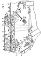
- the device-fixed axes 2 and 3 of a roller 4 and a roller 5 for an original 6 to be imaged are stored in a device frame 1.
- a swivel cable 8 is mounted, which carries an axis 9.
- the crank 10 of a four-link mechanism formed by a coupling member 11 and cranks 10 and 12 is articulated on the axis 9.
- the crank 12 of this four-link transmission is mounted on a fixed axis 13.
- the coupling joints of the transmission are formed by axes 14 and 15, of which the axis 14 forms the bearing axis for the feed roller 16 and the axis 15 forms the bearing axis for the extraction roller 17 of the roller pairs 4, 16 and 5, 17, one at each end of the axis Crank part 10a, 10b (Fig. 5) or 12a, 12b (not shown) of the crank 10 or 12 is articulated.
- the coupling member 11 is designed as a largely closed housing equipped with a cover plate 11 a for the pivotable rollers 16 and 17.
- a tension spring 19 engages with a relatively steep spring characteristic.
- the other end of the tension spring 19 is suspended on a pin 20 of a pivot lever 2.1.
- the pivot lever 21 is mounted on an axis 22 which is fastened to a slide 24 which is displaceable in a guide part 23.
- the carriage 24 is pressed against an adjusting screw 26 by means of a compression spring 25. As a result, the position of the axis 22 can be adjusted in the pulling direction of the spring 19.
- the pivot lever 21 carries yet another suspension pin 27, which by means of a Drawbar 28 is connected to the armature 29 of an electromagnet 30.
- the tie rod 29 has a collar 29a which, together with the upper edge 30a of the magnet 30, forms a fixed stop for the tie rod 29.
- the end of the tension spring 32 is attached to a device-fixed pin 33.
- the tension spring 32 pulls the pivot lever 8 against a fixed stop pin 34 until the spring 19 is tensioned by means of the magnet 29, 30.
- the pivot lever 8 is pulled down until the roller 16 bears against the upper part 35 of the device or the template 6, which is designed as a guideway for the template 6.
- the spring 19 By appropriate adjustment of the adjusting screw 26 or by moving the pivot point 22 in the direction of arrow AB it can be achieved that the spring 19 generates the normal pressing force for the roller 16 at the moment when this roller does not cover the surface of the roller with a template 6 4 touches.
- the setting of the pressing force takes place by shortening or lengthening the power chain between the magnets 29, 30 and the pivot lever 8 due to the relative displacement of the pins 20 and 27 in the pulling direction of the spring caused by the pivot point 22 being displaced.
- the characteristic of the spring 19 is designed so that after the entry of a thick template under the feed roller 16 and the resulting lifting of this roller, the force of the spring increases to the extent that it is for the reduction of the pressing force described in more detail below Roller 17 is required.
- the pressing force for the pull-out roller 17 is generated in that a spring 37 is suspended on a pin 36 of the crank 12, the other end of which is suspended on a bent-up tab 39 a of a tab 39 which is longitudinally displaceable in a guide 38.
- a set screw 41 is screwed through a bent-up tab 38 a of the guide 38 and 39 b of the tab 39 or a nut 40 abutting the tab 39 b, by means of which the spring 37 can be tensioned. In this way, it is possible to regulate the output voltage of the pressure spring 37.
- a pull rod 43 is attached to a pin 42 of an arm 12 a of the crank 12, which connects this pin to the tie rod 44 of a magnet 45.
- a collar 44 a of the tie rod 44 together with the upper edge of the magnet 45 forms a fixed stop for the tie rod 44.
- an imaging lens 46 is provided, which images an exposure window 35a formed in the upper part 35 of the device in a known manner on the moving recording medium.
- a transparent support plate 48 is inserted into the cover plate 35 for guiding the template 6.
- the copying process is initiated by means of a copy switch 53 which is connected to a central control unit 55 by means of a line 54. Another conductor 56 connects the copy switch 53 to a conductor 57 of a power line 57, 58.
- the central control unit 55 is connected by means of further lines 59 and 60 to a microswitch 61, the sensor 62 of which protrudes into the path of the original 6.
- the stop edge 63 a of a paper stop 63 mounted on the axis 14 also projects into this transport path.
- the paper stop 63 has a stop nose 63 b, which rests on the device upper part 35 at a location located next to the original transport path.
- the stop edge 63 a moves upwards at the moment in which the feed roller 16 lowers with its axis 14 downwards.
- the stop 63 a is thus automatically removed from the path of the template 6 with the lowering of the roller 16 or with the closing of the feed roller pair 4, 16.
- the paper stop 63 a is also removed from the path of the template 6 when the coupling member 11 is raised to such an extent that both pairs of rollers 4, 16 and 5, 17 are open.
- the central control unit 55 is designed in such a way that it produces the readiness for copying of the device by pressing the key of the copy switch 53. If a template 6 is now inserted under the roller 16 in the direction of the paper stop 63 a, the microswitch 61, 62 is actuated, as a result of which the central control unit 55 initiates the copying cycle of the device and also the magnet 29, 30 via a line 64 Closing the feed roller pair 4, 16 controls. Another line 65 connects the magnet 30 to the power conductor 58, whereby the circuit of the Magnet is closed.
- the holding relay 70 is connected to the mains conductor 58 via leads 71 and 72 by the switch 66.
- Another network conductor 73 connects the central control unit 55 to this network conductor.
- a line 69 connecting the relay 70 to the control unit 55 represents the holding circuit of this relay, which is opened when the copy switch 53 is actuated again.
- the central control unit 55 also contains circuit elements which cause the rollers 16 and 17 to be pivoted away from the original if, after the end of a normal copying cycle given by the length of the copying paper used, some of the Original is located over the paper sensor 62. If one now pushes the original 6 against the transport direction C by the width of the exposure window 35a with the pairs of rollers 4, 16 and 5, 17 open and then actuates the copy switch 53 again, the next exposure begins exactly at the point where the previous one Illumination has ended. You get a sheet-by-piece, complete image of the endless original.
- a perforated transport wheel 74 is also provided, the axis 78 of which is mounted on a pivotable arm 75 and engages with its teeth 74a in the generally perforated edge of the endless templates.
- the transport wheel 74 is rotated via a drive wheel 76 and a pinch 77 by a motor, not shown, also controlled by the central control unit 55, in the case of the automatic opening of the transport roller by a length corresponding to the exposure window 35 a piece as soon as the transport rollers in the previously described were opened by the central control unit 55 or by the paper sensor 62.
- Figure 3 shows the. open position of the original transport rollers.
- the magnet 29, 30 is de-energized and the spring 19 is thus relaxed.
- the tie rod 44 of the magnet 45 is tightened up to its stop.
- Characterized the crank 12 is pivoted so far clockwise that, in addition to the roller 15 via the coupling member 11, the roller 16 is pivoted away from its counter roller.
- the stop 79 arranged on the coupling member lifts the paper stop 63 a from the original transport surface 35, so that e.g. an endless copy to be copied, can be moved freely over the exposure window 35 a.
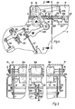
- FIG. 6 shows the relationship between the pressing force W, the pull-in roller and the pressing force W 2 of the pull-out roller as a function of the spring travel S in the form of a diagram. It can be seen that in the vicinity of the basic position G o indicated by a dash-dotted line, in which at de Rolls of the original transport plane 35 rest without an intermediate layer of a document to be transported, both roller pressure forces W I and W 2 have approximately the same size.
- the output magnitude of the forces W I and W 2 can be changed by adjusting the adjusting screws 26 and 41 (FIG. 1), as shown for example by the dashed lines W I 'and W 2 '.
- the diagram according to FIG. 6 corresponds to the case in which both cranks 10 and 12 are arranged at 45 °. In principle, the same conditions result for other crank angles. The reduced by the amounts .DELTA.W two pressing force W 2 would however not be more on the output line W 2nd
- FIG. 2 shows the conditions for springs 19 and 37 acting on the cranks 10 and 12, respectively.
- the spring forces could also be replaced in whole or in part by weight forces, whereby in the case of the pull-out roller 15 these spring or weight forces could act on the roller axis 17 in addition to in a direction perpendicular to the crank 12 in a direction perpendicular to the original transport plane 35.
- the pivot lever 108 on which the crank 10 formed by two crank parts for the feed roller 16 is articulated, is connected by means of a pull rod 82 to a pin 81 arranged on a pivot lever 80.
- the pull rod 28 of the magnet 29, 30, which excites the pressure spring for the feed roller engages.
- the adjusting screw 26 acts on the axis 83 of the pivot lever 80.
- the pivot lever 108 is fastened in this case by means of bushings 108 a and 108 b and adjusting screws 84 and 85 approximately in the middle of the axes 107 and 109 which extend essentially over the entire roller arrangement.
- the pivoting movement transmitted from the pull rod 82 to the pivoting lever 108 can therefore only propagate onto the crank parts 10a and 10b by using these long, resilient axes 107 and 109.
- the two axes 107 and 109 which are twisted with respect to one another by means of the pivoting lever 108 form a pressure spring of arbitrarily steep characteristics for the feed roller 16, which in this case is divided into several transport rollers 16 a to 16 c lined up on one axis.
Landscapes
- Physics & Mathematics (AREA)
- General Physics & Mathematics (AREA)
- Delivering By Means Of Belts And Rollers (AREA)
- Registering Or Overturning Sheets (AREA)
- Holders For Sensitive Materials And Originals (AREA)
- Exposure Or Original Feeding In Electrophotography (AREA)
- Optical Systems Of Projection Type Copiers (AREA)
Claims (12)
Applications Claiming Priority (2)
| Application Number | Priority Date | Filing Date | Title |
|---|---|---|---|
| DE2843522 | 1978-10-05 | ||
| DE19782843522 DE2843522C2 (de) | 1978-10-05 | 1978-10-05 | Vorlagenandruckvorrichtung für den Bildfensterbereich eines Durchlaufkopiergerätes |
Publications (2)
| Publication Number | Publication Date |
|---|---|
| EP0010604A1 EP0010604A1 (fr) | 1980-05-14 |
| EP0010604B1 true EP0010604B1 (fr) | 1982-11-03 |
Family
ID=6051519
Family Applications (1)
| Application Number | Title | Priority Date | Filing Date |
|---|---|---|---|
| EP19790103481 Expired EP0010604B1 (fr) | 1978-10-05 | 1979-09-17 | Tireuse à mouvement continu |
Country Status (3)
| Country | Link |
|---|---|
| EP (1) | EP0010604B1 (fr) |
| JP (1) | JPS5550259A (fr) |
| DE (1) | DE2843522C2 (fr) |
Families Citing this family (5)
| Publication number | Priority date | Publication date | Assignee | Title |
|---|---|---|---|---|
| JPS5680543U (fr) * | 1979-11-27 | 1981-06-30 | ||
| IT1129327B (it) * | 1980-10-20 | 1986-06-04 | Olivetti Ing C Spa | Alimentatore di originali per macchine copiarici |
| JPS57124840U (fr) * | 1981-01-27 | 1982-08-04 | ||
| JPH0789639B2 (ja) * | 1985-12-06 | 1995-09-27 | 富士写真フイルム株式会社 | 光ビーム走査装置 |
| JP2002090906A (ja) * | 2000-09-14 | 2002-03-27 | Noritsu Koki Co Ltd | 感光材料の平面性維持部材およびそれを備えた写真焼付装置 |
Family Cites Families (4)
| Publication number | Priority date | Publication date | Assignee | Title |
|---|---|---|---|---|
| CH442987A (de) * | 1966-10-12 | 1967-08-31 | Wissenschaftliches Forschungsi | Kopiergerät mit Durchlaufbelichtung |
| US3588244A (en) * | 1968-09-23 | 1971-06-28 | Icp Inc | Book copier attachment for a photocopy machine |
| US3689141A (en) * | 1970-05-19 | 1972-09-05 | Addressograph Multigraph | Electrostatic exposure time control |
| US3909128A (en) * | 1973-08-31 | 1975-09-30 | Xerox Corp | Control logic for changing a multi-mode copier/duplicator from one mode to another |
-
1978
- 1978-10-05 DE DE19782843522 patent/DE2843522C2/de not_active Expired
-
1979
- 1979-09-17 EP EP19790103481 patent/EP0010604B1/fr not_active Expired
- 1979-10-03 JP JP12692179A patent/JPS5550259A/ja active Granted
Also Published As
| Publication number | Publication date |
|---|---|
| JPS5550259A (en) | 1980-04-11 |
| DE2843522B1 (de) | 1979-11-15 |
| JPS5635868B2 (fr) | 1981-08-20 |
| EP0010604A1 (fr) | 1980-05-14 |
| DE2843522C2 (de) | 1980-07-31 |
Similar Documents
| Publication | Publication Date | Title |
|---|---|---|
| DE69119303T2 (de) | Blattzufuhrvorrichtung | |
| DE69619901T2 (de) | Automatischer Papierzuführer | |
| DE3018853C2 (de) | Fixiervorrichtung für Tonerbilder | |
| DE2539406C2 (de) | Blattfördervorrichtung, insbesondere für ein Kopiergerät | |
| DE68904810T2 (de) | Elektrophotographisches druckgeraet. | |
| DE69807144T2 (de) | Aufzeichnungsgerät | |
| DE69727116T2 (de) | Bilderzeugungsgerät für beidseitiges Drucken | |
| DE2857464C2 (de) | Zuführvorrichtung für bahnförmiges, in einer Kassette aufgerolltes Aufzeichnungsmaterial in einem Kopier- oder Vervielfältigungsgerät | |
| DE3836617C2 (fr) | ||
| DE2647265C2 (de) | Zuführvorrichtung für ein Fotokopiergerät | |
| DE1597397C3 (de) | Verfahren und Vorrichtung zum Vorlagenwechsel bei einem Kopiergerät | |
| DE3102293A1 (de) | Optisches kopiergeraet | |
| DE2546463C3 (de) | Blattzufuhrvorrichtung für eine Kopiermaschine | |
| DE3623075A1 (de) | Blatttransportvorrichtung | |
| DE3332143A1 (de) | Aufzeichnungsgeraet | |
| DE2647638A1 (de) | Handhabungsvorrichtung fuer vorlagen | |
| EP0010604B1 (fr) | Tireuse à mouvement continu | |
| DE3220235C2 (de) | Selbsttätiger Vorlagenanleger | |
| DE60109856T2 (de) | Bogenzuführvorrichtung | |
| DE19821758A1 (de) | Bilderzeugungsvorrichtung, die freigebbare Blattförderbahnen aufweist, und Verfahren für diese Vorrichtung | |
| DE69308901T2 (de) | Kopiereinrichtung mit zusätzlicher Papierzuführung | |
| DE2506857C3 (de) | VerschluUeinrichtung für die Kopiertisch-Abdeckung eines Kopiergerätes | |
| DE2945840C2 (de) | Vorrichtung zur Zuführung des obersten Blattes von einem Blattstapel für ein Kopiergerät | |
| DE68914889T2 (de) | Thermodruckverfahren. | |
| DE3872708T2 (de) | Blatttrennungsapparat. |
Legal Events
| Date | Code | Title | Description |
|---|---|---|---|
| PUAI | Public reference made under article 153(3) epc to a published international application that has entered the european phase |
Free format text: ORIGINAL CODE: 0009012 |
|
| AK | Designated contracting states |
Designated state(s): BE CH FR GB IT NL |
|
| 17P | Request for examination filed | ||
| ITF | It: translation for a ep patent filed | ||
| GRAA | (expected) grant |
Free format text: ORIGINAL CODE: 0009210 |
|
| AK | Designated contracting states |
Designated state(s): BE CH FR GB IT NL |
|
| ET | Fr: translation filed | ||
| PGFP | Annual fee paid to national office [announced via postgrant information from national office to epo] |
Ref country code: NL Payment date: 19830707 Year of fee payment: 5 |
|
| PGFP | Annual fee paid to national office [announced via postgrant information from national office to epo] |
Ref country code: BE Payment date: 19830831 Year of fee payment: 5 |
|
| PG25 | Lapsed in a contracting state [announced via postgrant information from national office to epo] |
Ref country code: CH Effective date: 19830930 |
|
| GBPC | Gb: european patent ceased through non-payment of renewal fee | ||
| PG25 | Lapsed in a contracting state [announced via postgrant information from national office to epo] |
Ref country code: FR Free format text: LAPSE BECAUSE OF NON-PAYMENT OF DUE FEES Effective date: 19840530 |
|
| REG | Reference to a national code |
Ref country code: CH Ref legal event code: PL |
|
| REG | Reference to a national code |
Ref country code: FR Ref legal event code: ST |
|
| PG25 | Lapsed in a contracting state [announced via postgrant information from national office to epo] |
Ref country code: BE Effective date: 19840930 |
|
| BERE | Be: lapsed |
Owner name: AGFA-GEVAERT A.G. Effective date: 19840917 |
|
| PG25 | Lapsed in a contracting state [announced via postgrant information from national office to epo] |
Ref country code: NL Effective date: 19850401 |
|
| NLV4 | Nl: lapsed or anulled due to non-payment of the annual fee | ||
| PG25 | Lapsed in a contracting state [announced via postgrant information from national office to epo] |
Ref country code: GB Effective date: 19881118 |
|
| PLBE | No opposition filed within time limit |
Free format text: ORIGINAL CODE: 0009261 |
|
| STAA | Information on the status of an ep patent application or granted ep patent |
Free format text: STATUS: NO OPPOSITION FILED WITHIN TIME LIMIT |