EP0010747B1 - Dispositif pour filtrer les liquides contenant des solides - Google Patents
Dispositif pour filtrer les liquides contenant des solides Download PDFInfo
- Publication number
- EP0010747B1 EP0010747B1 EP79104163A EP79104163A EP0010747B1 EP 0010747 B1 EP0010747 B1 EP 0010747B1 EP 79104163 A EP79104163 A EP 79104163A EP 79104163 A EP79104163 A EP 79104163A EP 0010747 B1 EP0010747 B1 EP 0010747B1
- Authority
- EP
- European Patent Office
- Prior art keywords
- filter
- filter band
- cleaning
- band
- region
- Prior art date
- Legal status (The legal status is an assumption and is not a legal conclusion. Google has not performed a legal analysis and makes no representation as to the accuracy of the status listed.)
- Expired
Links
- 239000007788 liquid Substances 0.000 title claims abstract description 14
- 239000007787 solid Substances 0.000 title claims abstract description 14
- 238000001914 filtration Methods 0.000 title claims abstract description 8
- 238000004140 cleaning Methods 0.000 claims abstract description 41
- XLYOFNOQVPJJNP-UHFFFAOYSA-N water Substances O XLYOFNOQVPJJNP-UHFFFAOYSA-N 0.000 claims abstract description 11
- 241000219310 Beta vulgaris subsp. vulgaris Species 0.000 claims abstract description 7
- 235000021536 Sugar beet Nutrition 0.000 claims abstract description 7
- 238000007873 sieving Methods 0.000 claims abstract 2
- 238000007789 sealing Methods 0.000 claims description 6
- 239000013013 elastic material Substances 0.000 claims description 2
- 230000001174 ascending effect Effects 0.000 claims 1
- 238000010276 construction Methods 0.000 description 6
- 239000004744 fabric Substances 0.000 description 4
- CZMRCDWAGMRECN-UHFFFAOYSA-N Rohrzucker Natural products OCC1OC(CO)(OC2OC(CO)C(O)C(O)C2O)C(O)C1O CZMRCDWAGMRECN-UHFFFAOYSA-N 0.000 description 3
- 230000000694 effects Effects 0.000 description 3
- 239000012065 filter cake Substances 0.000 description 3
- 239000000463 material Substances 0.000 description 3
- 239000002245 particle Substances 0.000 description 3
- 239000004576 sand Substances 0.000 description 3
- 238000005406 washing Methods 0.000 description 3
- 235000016068 Berberis vulgaris Nutrition 0.000 description 2
- 241000335053 Beta vulgaris Species 0.000 description 2
- 230000015572 biosynthetic process Effects 0.000 description 2
- 239000000470 constituent Substances 0.000 description 2
- 230000000284 resting effect Effects 0.000 description 2
- 239000000126 substance Substances 0.000 description 2
- 241000196324 Embryophyta Species 0.000 description 1
- 230000009471 action Effects 0.000 description 1
- 230000009172 bursting Effects 0.000 description 1
- 238000011161 development Methods 0.000 description 1
- 230000018109 developmental process Effects 0.000 description 1
- 230000006872 improvement Effects 0.000 description 1
- 230000003993 interaction Effects 0.000 description 1
- 230000007246 mechanism Effects 0.000 description 1
- 238000000034 method Methods 0.000 description 1
- 230000008569 process Effects 0.000 description 1
- 238000000746 purification Methods 0.000 description 1
- 238000007665 sagging Methods 0.000 description 1
- 238000010408 sweeping Methods 0.000 description 1
Images


Classifications
-
- B—PERFORMING OPERATIONS; TRANSPORTING
- B01—PHYSICAL OR CHEMICAL PROCESSES OR APPARATUS IN GENERAL
- B01D—SEPARATION
- B01D33/00—Filters with filtering elements which move during the filtering operation
- B01D33/04—Filters with filtering elements which move during the filtering operation with filtering bands or the like supported on cylinders which are impervious for filtering
-
- B—PERFORMING OPERATIONS; TRANSPORTING
- B01—PHYSICAL OR CHEMICAL PROCESSES OR APPARATUS IN GENERAL
- B01D—SEPARATION
- B01D33/00—Filters with filtering elements which move during the filtering operation
- B01D33/056—Construction of filtering bands or supporting belts, e.g. devices for centering, mounting or sealing the filtering bands or the supporting belts
Definitions
- the invention relates to a device for filtering liquids containing solids, in particular for filtering water-flush flow for the transport of sugar beets in a beet sugar factory, with an endless, rotating filter belt with sieve or filter openings, the upper strand of which serves as a sieve surface, and with a the filter belt cleaning station located downstream of the upper run, in the area of which the filter belt can be stretched by widening the sieve or filter openings.
- Beet sugar factories are mostly set up so that By J '' ie agriculture are promoted delivered sugar beet ⁇ nem system of channels by a wassiden Schwemmstrom on the Betreospond the factory.
- the sugar beet reached by all foreign bodies, so beet leaves, weeds, sand, stones etc.
- the unwanted constituents and foreign bodies are separated from the beet during transport and removed from the sweeping stream in appropriate stations widely clarified that it can be returned to the wash stream to form a closed circuit.
- the clarifier as the final stage of water purification is usually preceded by a sand trap and a filter.
- the latter is used to separate particularly fine solids, especially organic components, from the water.
- the present invention is concerned with the improvement of the latter device.
- the main aim is to increase the efficiency of the filter device in the simplest possible way by avoiding the sealing of the filter openings of the filter belt.
- GB-A-532750 can be removed, in order to improve the cleaning and thus the filter performance of the filter belt, to stretch it in the area of the cleaning station by widening the sieve or filter openings.
- this is done in such a way that the filter belt is stretched in the longitudinal direction by stretching rollers which are driven much faster than the other deflecting rollers.
- the screen or filter openings are widened or stretched between two pairs of stretching rollers in the conveying direction of the filter belt.
- the filter belt is sprinkled with a cleaning liquid in the cleaning station.
- GB-A-532750 also proposes to simultaneously stretch the filter belt in the cleaning station in the transverse direction by means of a tensioning frame, so that in the cleaning station the sieve or filter openings are widened both in the longitudinal and in the transverse direction of the filter belt .
- a disadvantage of the known construction is that either separate drives or at least one additional gear are required for the stretching rollers. Furthermore, a special clamping frame for the transverse expansion of the filter belt must be provided. The known construction is therefore relatively complex.
- the additional cleaning with a cleaning liquid is also accompanied by a certain effort, since an additional liquid circuit with pumps, catch basins, sieves, filters is required.
- a so-called "cake removal device for drum filters with a running filter cloth is known, in which the filter cloth or filter belt is guided over rollers, one of which has ridges for" the filter cake bursting or flaking off.
- the ridges each have a sinusoidal shape, where they rest in the valley of the sinus curve on the roller jacket of the deflecting roller and move away from the jacket until the upper vertex of the sinus curve is reached.
- the arrangement of the elevations is chosen so that the filter cloth is only stretched at individual points, and that these points “move” over the width of the roller or over the width of a sine curve in the course of one revolution of the deflecting roller.
- DE-B-1 285454 thus conveys the teaching of mounting elevations on a deflecting roller in such a way that the "expansion point moves parallel to the roller axis during one roller revolution and that only in this way can the filter cake be broken into small pieces.
- the present invention is therefore based on the object of providing a filter device of the type mentioned at the outset which, with relatively simple means, permits a higher filter effect due to improved cleaning of the endless filter belt running around.
- the cleaning station contains at least one deflection roller, via which Filter band is guided and which is provided on the outside of its jacket with ribs that stretch the filter band across its entire width in the transverse direction.
- the solution according to the invention is characterized by a conceivably simple, yet highly effective construction. Additional drives for stretching rollers for widening the screen or filter openings in the conveying direction of the filter belt or clamping frames for widening the screen or filter openings transversely to the conveying direction of the filter belt are not required.
- the invention allows. Solution the formation of relatively fine filter openings with the result that a layer of settled solids is constantly formed on the filter belt, which has the effect of an additional filter in the area of the upper run of the liquid. At the same time, however, sealing or clogging of the filter openings is effectively avoided by the measures according to the invention. Additional suction, compressed air or washing facilities are not required.
- the filter device shown here as an exemplary embodiment is primarily intended for use in the operation of a beet sugar factory, that is to say for cleaning or filtering flood water with fine solids, such as sand and organic constituents.
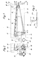
- a filter surface of the device is formed by an endless filter belt 10. According to FIG. 1, this is guided over three deflecting rollers 1.1, 12, 13, which are arranged in the corners of a triangle.
- the filter belt 10 is thereby given an approximately triangular shape in a side view.
- the deflection roller 11 is also designed as a tension roller with a tensioning device 14.
- the drive of the continuously rotating filter belt 10 is effected by the deflection roller 12, which in turn is driven by a motor 15 via a belt drive 16.
- the deflection rollers 11, 12, 13 are otherwise supported in a support frame 17.
- the filter belt 10 is cleaned outside the area of the protruding screen surface.
- the cleaning strands 20 guided between the deflecting rollers 12, 13 are assigned cleaning units to be explained in detail.
- the cleaning strand 20 is guided by the arrangement of the deflecting rollers 12, 13 so that in this area the filter belt 10 is guided somewhat out of the vertical, so that the solids accumulating during the cleaning process can fall down freely.
- the filter band 10 is designed in a special way. It consists of an elastically stretchable material, in particular plastic.
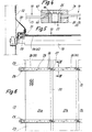
- the filter belt 10 consists of a plurality of webs 21a, 21b, 21c lying side by side in the direction of rotation. These are arranged relative to one another in such a way that there is an overlap 22 between adjacent tracks 21a, 21b.
- Each web 21a, 21b .. in turn in the present case consists of individual rectangular mats 23 of an appropriate size.
- the mats 23 are detachable in the circumferential direction connected, so that each mat 23 can be replaced individually if necessary.
- common, transverse joints 27, 28 are provided for the mats 23 of all webs 21 a, 21 b ..
- the butt and connection points 27, 28 of the mats 23 are formed here by clamping strips 24, 25, which capture the mutually facing edges of successive mats 23 and connect them to one another by positive locking and clamping action.
- a clamping strip 24 or 25 is arranged on both sides of the mats 23. Both terminal strips 24, 25 are gripped and held together by a connecting screw 26 which can be operated from above.
- these are provided with holes 45 on the mutually facing edges in the region of an overlap also formed there. These are pressed with a widening over a holding pin 46 of the terminal strips 24, 25 and thereby fixed or pre-fixed.
- the upper, free end of these holding pins 46 is formed with a barb-like widening 47, by means of which the mats 23 are pressed while the holes 45 are widened.
- two mats 23 with the edges lie one above the other in this area.
- the holding pin 46 is anchored, for example, with a thread in the lower terminal strip 25.
- An internally threaded bore in the holding pin 46 receives the connecting screw 26, whereby the clamping strips 24, 25 are pressed against one another or against the mats 23 while exerting a considerable clamping pressure.
- the terminal strips 24, 25 consist of individual sections, each with a length that corresponds to the width of a track 21a, 21b ..
- the sections of the respective terminal strips 24 in the area of the overlap 22 are provided with an also overlapping joint 27.
- joints 28 of the lower terminal strips 25 are provided.
- the clamping strips 24, 25 which extend in this way over the entire width of the filter belt 10 stabilize the filter belt 10 and at the same time guide in the lateral area.
- support rollers 29 are arranged on the free ends of the clamping strips 24, 25, which protrude beyond the filter belt 10 and are supported on an upright lateral guide rail 30 of the device in the region of the upper strand 18.
- these support rollers 29 are arranged outside the filter area, which is laterally limited by an elastic limitation in the form of a sealing tab 31 resting on the filter belt 10.
- This sealing tab 31 is in turn arranged on a side wall 32 projecting inwards here, which in turn delimits the space or area for receiving the liquid to be cleaned.
- the filter belt 10 can be equipped with relatively small filter openings 33.
- these are rectangular and extend in the longitudinal direction, that is to say in the direction of movement of the filter band 10.
- the filter openings 33 arranged in rows are offset or arranged in a gap with respect to one another.
- a deformation of the filter openings 33 in the sense of FIG. 9 is possible, namely by transverse expansion of the filter belt 10. Any solid particles that may be jammed in the fine filter openings 33 can thereby be removed, particularly in connection with a cleaning unit 35.
- the transverse stretching of the filter belt 10 in the above sense takes place in the region of the deflecting roller 13, which is provided with annularly arranged ribs 34 on its jacket.
- the ribs 34 consist of welded rings made of round material.
- the ribs 34 can be arranged in a helical manner, as a result of which the filter band 10 is stretched or stretched over the width in different areas during the repeating cycles.
- the cross-sectional shape of the filter belt 10 shown in FIG. 7 results in the region of the deflecting roller 13, with the result that the filter openings 33 are widened in the sense of FIG. 9.
- the filter openings 33 can thereby have the smallest width dimensions, for example down to 0.1 mm.
- a cleaning unit 35 assigned to the cleaning strand 20 in the present case comprises a cleaning strip 36 which can be delivered to the cleaning strand 20. This is driven in such a way that it carries out a relative movement to the filter belt 10 such that this cleaning tool knocks or strikes the filter belt 10 is moved up.
- a crank mechanism 37 is provided for the movement of the cleaning bar 36.
- a fixed, elastic scraper 38 Downstream in the direction of movement is a fixed, elastic scraper 38, which also extends over the entire width of the filter belt 10.
- This wiper 38 which is made of elastic material, is constantly in contact with the moving filter belt 10. A certain contact pressure in the area of the widened filter openings 33 pulls out solid particles, particularly threads, etc., which are seated therein.
- the filter surface of the filter belt 10, namely the upper run 18, is accommodated in an upwardly open container which has a greater depth on the inlet side due to the inclined arrangement of the upper run 18.
- the liquid is supplied via an overflow 39.
- the overflow 39 is preceded by a transversely extending collecting trough 40 in which any energy of the inflowing water is destroyed.
- a baffle plate 41 arranged above the collecting trough 40 has the same task.
- the overflow 39 in connection with the side wall 32 and the upper run 18 thus creates a container for holding the liquid to be cleaned, from which the filter surface can be moved continuously by the filter. Band 10 is constantly moved out.
- FIG. 3 shows a detail of the filter belt 10 in the area of the overlaps 22.
- an elastic hold-down 42 above the filter belt 10 is in each case here Area of the overlaps 22 arranged.
- the flap-like or strip-shaped hold-down device 42 is anchored above the filter belt 10 in corresponding holding rails 48 in such a way that the hold-down device 42 deflected in an arc shape by 90 ° rests on the filter belt 10 with a corresponding contact pressure in the region of the overlap 22.
- the relative arrangement and dimensions of the hold-down device 42 are selected such that the free step formed in the area of the overlap 22 is covered.
- the configuration according to FIG. 11 serves the same subject, namely the arrangement of the support rollers 19 along an arc.
- the filter belt 10 is guided in a polygonal manner in the region of the upper run 18.
- the exposed sections of the filter belt 10 are thereby given a higher tension, so that the overlapping edges of the webs 21a, 21b.
- a large-scale container 43 is formed for receiving the cleaned liquid. From this, the water can be discharged via large outlet openings 44 which are preferably arranged on both sides.
- an elastic apron 49 resting on the filter belt 10 is formed, which is designed essentially in the same or similar manner as the sealing tab 31 in the area of the side wall 32.
- the task of this Apron 49 is on the one hand the seal of the “rail container” formed here for holding the liquid to be cleaned on the “valley side” of the filter belt 10.
- the fixed apron 49 which is oriented transversely to the filter belt 10, has the function of a further cleaning element. Any solids still adhering to or on the filter belt 10 in this area are removed here.
- the cleaning elements arranged in a fixed relative position in particular the scraper 38 and the aforementioned apron 49, are in turn permanently freed of the residues collected, namely by the clamping strips 24 arranged as an increase on the filter belt 10. These become corresponding to the length of the mats 23 successively guided past the scraper 38 and the apron 49, with the result that solid parts deposited here are carried along by the terminal strips 24.
Landscapes
- Chemical & Material Sciences (AREA)
- Chemical Kinetics & Catalysis (AREA)
- Filtration Of Liquid (AREA)
Claims (12)
Priority Applications (1)
| Application Number | Priority Date | Filing Date | Title |
|---|---|---|---|
| AT79104163T ATE1565T1 (de) | 1978-11-02 | 1979-10-27 | Vorrichtung zum filtern von feststoffe enthaltenden fluessigkeiten. |
Applications Claiming Priority (2)
| Application Number | Priority Date | Filing Date | Title |
|---|---|---|---|
| DE19782847503 DE2847503A1 (de) | 1978-11-02 | 1978-11-02 | Vorrichtung zum filtern von feststoffe enthaltenden fluessigkeiten |
| DE2847503 | 1978-11-02 |
Publications (2)
| Publication Number | Publication Date |
|---|---|
| EP0010747A1 EP0010747A1 (fr) | 1980-05-14 |
| EP0010747B1 true EP0010747B1 (fr) | 1982-09-22 |
Family
ID=6053666
Family Applications (1)
| Application Number | Title | Priority Date | Filing Date |
|---|---|---|---|
| EP79104163A Expired EP0010747B1 (fr) | 1978-11-02 | 1979-10-27 | Dispositif pour filtrer les liquides contenant des solides |
Country Status (3)
| Country | Link |
|---|---|
| EP (1) | EP0010747B1 (fr) |
| AT (1) | ATE1565T1 (fr) |
| DE (2) | DE2847503A1 (fr) |
Families Citing this family (2)
| Publication number | Priority date | Publication date | Assignee | Title |
|---|---|---|---|---|
| NL8300712A (nl) * | 1983-02-25 | 1984-09-17 | Esmil Hubert Bv | Bandfilter. |
| FR2596416A1 (fr) * | 1986-03-27 | 1987-10-02 | Siderurgie Fse Inst Rech | Procede et dispositif de controle du positionnement d'une lance d'injection dans un recipient metallurgique |
Family Cites Families (5)
| Publication number | Priority date | Publication date | Assignee | Title |
|---|---|---|---|---|
| US1663298A (en) * | 1925-06-17 | 1928-03-20 | Goodrich Co B F | Rubber filter sheet |
| US2173256A (en) * | 1938-10-01 | 1939-09-19 | Us Rubber Co | Method and apparatus for filtering |
| DE1285454B (de) * | 1966-07-30 | 1968-12-19 | Krauss Maffei Imp Gmbh | Kuchenabnahmevorrichtung fuer Trommelfilter mit ablaufendem Filtertuch |
| US3703963A (en) * | 1969-07-24 | 1972-11-28 | Ebara Infilco | Sludge hydroextractor |
| US3570674A (en) * | 1969-10-14 | 1971-03-16 | American Air Filter Co | Liquid filter apparatus |
-
1978
- 1978-11-02 DE DE19782847503 patent/DE2847503A1/de not_active Withdrawn
-
1979
- 1979-10-27 EP EP79104163A patent/EP0010747B1/fr not_active Expired
- 1979-10-27 DE DE7979104163T patent/DE2963748D1/de not_active Expired
- 1979-10-27 AT AT79104163T patent/ATE1565T1/de not_active IP Right Cessation
Also Published As
| Publication number | Publication date |
|---|---|
| EP0010747A1 (fr) | 1980-05-14 |
| DE2963748D1 (en) | 1982-11-04 |
| ATE1565T1 (de) | 1982-10-15 |
| DE2847503A1 (de) | 1980-05-08 |
Similar Documents
| Publication | Publication Date | Title |
|---|---|---|
| DE102007036553A1 (de) | Vorrichtung zum Abscheiden von Lack-Overspray | |
| DE2330915A1 (de) | Verfahren und vorrichtung zum ausscheiden von feststoffen aus fluessigkeiten | |
| EP0581770A1 (fr) | Rateau cribleur. | |
| DE3409826A1 (de) | Filtervorrichtung zum abscheiden von feststoffen aus fluessigkeiten | |
| EP2563973B1 (fr) | Machine à tamis sans fin | |
| EP0010747B1 (fr) | Dispositif pour filtrer les liquides contenant des solides | |
| DE3003827C2 (de) | Einrichtung zur mechanischen Reinigung von Wässern | |
| EP2868822A1 (fr) | Dispositif de tamisage destiné à la séparation et à l'évacuation d'impuretés à partir d'eaux usées | |
| DE2745141A1 (de) | Staubfilter | |
| AT515829B1 (de) | Recheneinrichtung | |
| DE2318729A1 (de) | Waschvorrichtung fuer rueben od. dgl | |
| EP0563081B1 (fr) | Procede pour le nettoyage d'un separateur de gouttelettes et separateur de gouttelettes avec dispositif de nettoyage | |
| DE102007036551B4 (de) | Vorrichtung zum Abscheiden von Overspray | |
| EP0505018A1 (fr) | Filtre à plusieurs étages | |
| DE1407956A1 (de) | Trockenfilter-Reinigungssystem | |
| DE19727354A1 (de) | Siebeinrichtung | |
| DE3725651C1 (en) | Band filter for cleansing liq. - includes upper chamber to hold dirty liq. filter band drive unit and cleansing chamber | |
| DE3445123A1 (de) | Insbesondere im bergbau einsetzbare filteranlage zur luftentstaubung | |
| DE19746368A1 (de) | Combiscreen | |
| DE20215591U1 (de) | Förderband-Filtereinrichtung | |
| DE2925974C2 (de) | Recheneinrichtung zur Fremdkörperentfernung von einem Rechenrost | |
| DE1700712U (de) | Filter. | |
| DE19919690C2 (de) | Filterstufenrechen zum Sammeln und Abgeben von festen Bestandteilen aus strömenden Flüssigkeiten | |
| DE102011011759A1 (de) | Magnetabscheidevorrichtung und Magnetabscheideverfahren zum Abscheiden von ferromagnetischen Teilchen aus einer damit belasteten Flüssigkeit | |
| DE3433435A1 (de) | Siebvorrichtung zum reinigen von waessern und abwaessern |
Legal Events
| Date | Code | Title | Description |
|---|---|---|---|
| PUAI | Public reference made under article 153(3) epc to a published international application that has entered the european phase |
Free format text: ORIGINAL CODE: 0009012 |
|
| AK | Designated contracting states |
Designated state(s): AT BE DE FR GB IT NL SE |
|
| 17P | Request for examination filed | ||
| ITF | It: translation for a ep patent filed | ||
| GRAA | (expected) grant |
Free format text: ORIGINAL CODE: 0009210 |
|
| AK | Designated contracting states |
Designated state(s): AT BE DE FR GB IT NL SE |
|
| PG25 | Lapsed in a contracting state [announced via postgrant information from national office to epo] |
Ref country code: SE Free format text: THE PATENT HAS BEEN ANNULLED BY A DECISION OF A NATIONAL AUTHORITY Effective date: 19820922 |
|
| REF | Corresponds to: |
Ref document number: 1565 Country of ref document: AT Date of ref document: 19821015 Kind code of ref document: T |
|
| REF | Corresponds to: |
Ref document number: 2963748 Country of ref document: DE Date of ref document: 19821104 |
|
| PGFP | Annual fee paid to national office [announced via postgrant information from national office to epo] |
Ref country code: AT Payment date: 19901011 Year of fee payment: 12 |
|
| PGFP | Annual fee paid to national office [announced via postgrant information from national office to epo] |
Ref country code: FR Payment date: 19901012 Year of fee payment: 12 |
|
| PGFP | Annual fee paid to national office [announced via postgrant information from national office to epo] |
Ref country code: GB Payment date: 19901018 Year of fee payment: 12 |
|
| PGFP | Annual fee paid to national office [announced via postgrant information from national office to epo] |
Ref country code: DE Payment date: 19901026 Year of fee payment: 12 |
|
| ITTA | It: last paid annual fee | ||
| PGFP | Annual fee paid to national office [announced via postgrant information from national office to epo] |
Ref country code: NL Payment date: 19901031 Year of fee payment: 12 |
|
| PGFP | Annual fee paid to national office [announced via postgrant information from national office to epo] |
Ref country code: BE Payment date: 19901129 Year of fee payment: 12 |
|
| PG25 | Lapsed in a contracting state [announced via postgrant information from national office to epo] |
Ref country code: GB Effective date: 19911027 Ref country code: AT Effective date: 19911027 |
|
| PG25 | Lapsed in a contracting state [announced via postgrant information from national office to epo] |
Ref country code: BE Effective date: 19911031 |
|
| BERE | Be: lapsed |
Owner name: GERLACH GUNTER Effective date: 19911031 |
|
| PG25 | Lapsed in a contracting state [announced via postgrant information from national office to epo] |
Ref country code: NL Effective date: 19920501 |
|
| NLV4 | Nl: lapsed or anulled due to non-payment of the annual fee | ||
| GBPC | Gb: european patent ceased through non-payment of renewal fee | ||
| PG25 | Lapsed in a contracting state [announced via postgrant information from national office to epo] |
Ref country code: FR Effective date: 19920630 |
|
| PG25 | Lapsed in a contracting state [announced via postgrant information from national office to epo] |
Ref country code: DE Effective date: 19920701 |
|
| REG | Reference to a national code |
Ref country code: FR Ref legal event code: ST |
|
| PLBE | No opposition filed within time limit |
Free format text: ORIGINAL CODE: 0009261 |
|
| STAA | Information on the status of an ep patent application or granted ep patent |
Free format text: STATUS: NO OPPOSITION FILED WITHIN TIME LIMIT |