EP0505018A1 - Filtre à plusieurs étages - Google Patents
Filtre à plusieurs étages Download PDFInfo
- Publication number
- EP0505018A1 EP0505018A1 EP92250061A EP92250061A EP0505018A1 EP 0505018 A1 EP0505018 A1 EP 0505018A1 EP 92250061 A EP92250061 A EP 92250061A EP 92250061 A EP92250061 A EP 92250061A EP 0505018 A1 EP0505018 A1 EP 0505018A1
- Authority
- EP
- European Patent Office
- Prior art keywords
- filter
- belt
- filter belt
- scraper
- cake
- Prior art date
- Legal status (The legal status is an assumption and is not a legal conclusion. Google has not performed a legal analysis and makes no representation as to the accuracy of the status listed.)
- Granted
Links
Images



Classifications
-
- B—PERFORMING OPERATIONS; TRANSPORTING
- B01—PHYSICAL OR CHEMICAL PROCESSES OR APPARATUS IN GENERAL
- B01D—SEPARATION
- B01D25/00—Filters formed by clamping together several filtering elements or parts of such elements
- B01D25/12—Filter presses, i.e. of the plate or plate and frame type
- B01D25/127—Filter presses, i.e. of the plate or plate and frame type with one or more movable filter bands arranged to be clamped between the press plates or between a plate and a frame during filtration, e.g. zigzag endless filter bands
- B01D25/1275—Filter presses, i.e. of the plate or plate and frame type with one or more movable filter bands arranged to be clamped between the press plates or between a plate and a frame during filtration, e.g. zigzag endless filter bands the plates or the frames being placed in a non-vertical position
-
- B—PERFORMING OPERATIONS; TRANSPORTING
- B01—PHYSICAL OR CHEMICAL PROCESSES OR APPARATUS IN GENERAL
- B01D—SEPARATION
- B01D25/00—Filters formed by clamping together several filtering elements or parts of such elements
- B01D25/32—Removal of the filter cakes
- B01D25/38—Removal of the filter cakes by moving parts, e.g. scrapers, contacting stationary filter elements sprayers
Definitions
- the invention relates to a multi-layer filter, consisting of a plurality of filter plates arranged horizontally one above the other, each of which is held in parallel planes by a frame surrounding it, a filtrate and a turbidity chamber being alternately formed between adjacent filter plates and frame, and in each case between two filter plates by means of a transport device, a filter belt that can be moved in sections is arranged, which can be unwound from a supply roll arranged outside the floor filter and can be wound onto at least one collecting roll after removal of the filter cake, and for stripping the filter cake from the filter belt between the floor filter and collecting roll at least one arranged transversely and obliquely to the filter belt , on the surface of the filter belt is provided wipers to which an abutment provided below the filter belt is assigned.
- Floor filters of this type are known. They are pressure filters in which the filter plates can be pressed together with their frames lying one on top of the other, the filtrate being able to be fed in and discharged through frame or outlet openings provided in the plates or frames. The filtering process takes place when the plates are pressed together, the filter belt arranged between the filter plates being clamped. The filtrate flows through the filter plates, whereby dirt particles settle on the filter belt. The resulting filter cake must be removed from the deck filter from time to time. For this purpose, the filter plates with their frames are moved apart with a corresponding device, so that with the aid of a transport device, for example a pull-out device, the contaminated section of the filter belt is pulled out and, at the same time, clean filter belt is drawn in.
- a transport device for example a pull-out device
- the filter cake is wiped off on a deflection roller of the filter belt. ie by deflecting the belt, the filter cake is broken and crumbles, so that it can fall into a receiving means arranged below the filter belt.
- this type of disposal is disadvantageous because the deflection of the filter tape hinders the subsequent winding of the filter tape freed from the dirty cake onto collecting rolls for reasons of space. Problems also arise for the tape guide.
- EP 03 03 597 proposes to guide the filter belt around a deflection edge arranged obliquely to the belt direction and to sweep the lower surface of the belt upwards. This is intended on the one hand to achieve better belt guidance and on the other hand to enable the filter cake to be removed efficiently. Due to the large number of pulleys, this solution is very complex and therefore vulnerable and requires extensive maintenance.
- the present invention is based on the object of improving a multi-stage filter of the generic type in such a way that with a straight belt guide, a simple stripping system enables the dirt cake to be removed from the filter belt safely.
- At least one wiper arranged transversely and obliquely to the filter belt and resting on the surface of the filter belt is provided for stripping the filter cake from the filter belt between the floor filter and collecting roller, to which an abutment provided below the filter belt is assigned.
- the scraper consists of a rigid profile which extends obliquely to the running direction of the filter belt and extends the entire filter belt width and guides the filter cake in a direction to the side of the filter belt.
- the intended design of the scraper creates a very simple scraper system that is low in wear and requires little maintenance, which is also space-saving and inexpensive.
- the oblique arrangement of the scraper leads the dirt cake to the side of the filter belt when the filter belt is being transported, where a container is arranged at the discharge point.
- the abutment is a pressure plate holding the filter band against the stripper.
- the small distance between the pressure plate and the collar scraper allows the scraper to loosen the filter cake like a scraper knife and remove it laterally.
- the scraper is arranged in a V-shape lying on the filter belt in such a way that the legs of the scraper run outwards on both sides in the transport direction of the filter belt.
- a plurality of wipers running essentially parallel to one another are provided, which overlap one another over the entire filter bandwidth in a projection intended in the transport direction.
- the abutment is a rounded profile which is arranged obliquely to the direction of the filter belt and to which a wiper arranged in parallel in the direction of transport is assigned, the wiper edge of the wiper being immersed in the plane of the filter belt and the filter belt rolling over the abutment.
- This proposal removes the dirt cake from the filter belt in a particularly advantageous manner by means of the milling process and removes it safely by means of the scraper.
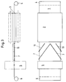
- 1 denotes the filter belt, which consists, for example, of a fiber fleece.
- the multi-level filter is indicated at 2, which consists of a plurality of filter plates 3 arranged one above the other, two of which filter plates 3 enclosing the filter belt 1 are shown.
- the filter belt is unrolled from a supply roll 4 and, in the extended position of the filter plates 3, is pulled out by one cycle length from the multi-stage filter 2 by means of the transport device 5, which is not explained in more detail, around the dirt cake accumulated on the filter belt to remove.
- the filter belt 1 cleaned from the dirty cake is wound onto a collecting roll at 6 and can later be fed to a cleaning process.
- the scraper 7 For stripping the dirt cake from the filter belt 1, the scraper 7 is provided, which consists of a flat iron profile, which is held transversely and obliquely (as the plan view shows) on the surface of the filter belt 1 by (not shown) holding means.
- An abutment 8 is provided on the underside of the filter belt 1, which consists, for example, of a pressure plate which extends over the entire underside of the filter belt 1 in the area of the scraper 7.
- the transport device which consists of the filter belt between pinching pinch rollers, engages the clean filter belt in order to feed it to the winding roller.
- FIG. 1 Another scraper device according to the invention is shown in FIG. The same parts are labeled the same.
- the scraper 7 is V-shaped here, the tip being directed against the transport direction of the filter belt 1 and the legs extending outward in the transport direction.
- the dirt cake on the filter belt is divided into two portions, which are thrown off in the arrow directions 10 on both sides of the filter belt.
- This device has the advantage that a quantity of dirty cake only has to be transported at most over half a width of the filter belt.
- FIG. 3 In order to prevent larger amounts of the dirt cake from accumulating in the edge region, another configuration of the scraper is proposed, which is shown in FIG. 3.
- two further wipers 11 are arranged parallel to the legs of the wiper 7, which, however, only sweep over the edge region of the filter belt 1.
- These wipers 11 already remove part of the dirt cake from the edge area, so that the wiper 7 wipes the middle area of the filter belt 1 and there is no jam of the dirt cake in the edge area of the wiper 7.
- the scraper shown in FIG. 4 works particularly cheaply.
- the abutment 8 is designed as a round rod over which the filter belt 1 is guided.
- the arranged at the top of the filter belt 1 scraper 7 is adjusted so far that it forces the filter belt 1 over the abutment 8 and thereby causes the dirt cake to break.
- the dirt cake thus detached from the filter belt is discharged laterally from the filter belt in the direction 10 by the scraper 7, which is here shaped like a bowl, in the same way as described with reference to FIG.
Landscapes
- Chemical & Material Sciences (AREA)
- Chemical Kinetics & Catalysis (AREA)
- Filtration Of Liquid (AREA)
- Treatment Of Sludge (AREA)
Applications Claiming Priority (2)
| Application Number | Priority Date | Filing Date | Title |
|---|---|---|---|
| DE9103729U | 1991-03-22 | ||
| DE9103729U DE9103729U1 (de) | 1991-03-22 | 1991-03-22 | Etagenfilter |
Publications (2)
| Publication Number | Publication Date |
|---|---|
| EP0505018A1 true EP0505018A1 (fr) | 1992-09-23 |
| EP0505018B1 EP0505018B1 (fr) | 1995-07-12 |
Family
ID=6865705
Family Applications (1)
| Application Number | Title | Priority Date | Filing Date |
|---|---|---|---|
| EP92250061A Expired - Lifetime EP0505018B1 (fr) | 1991-03-22 | 1992-03-16 | Filtre à plusieurs étages |
Country Status (3)
| Country | Link |
|---|---|
| US (1) | US5308486A (fr) |
| EP (1) | EP0505018B1 (fr) |
| DE (2) | DE9103729U1 (fr) |
Families Citing this family (8)
| Publication number | Priority date | Publication date | Assignee | Title |
|---|---|---|---|---|
| US5238584A (en) * | 1992-01-28 | 1993-08-24 | J. R. Schneider Co., Inc. | Apparatus for removing filtrate from filter media |
| JP3423041B2 (ja) * | 1993-10-07 | 2003-07-07 | 三洋電機株式会社 | 神経モデル素子 |
| DE4341580C1 (de) * | 1993-12-07 | 1995-02-16 | Bellmer Gmbh & Co Kg Geb | Vorrichtung zur Entwässerung von Suspensionen |
| DE19707070C2 (de) * | 1997-02-22 | 1999-04-01 | Netzsch Erich Holding | Filterpresse |
| US20110132831A1 (en) * | 2009-12-07 | 2011-06-09 | Flsmidth A/S | Horizontal belt vacuum filter with overhead fluid removal |
| KR102304049B1 (ko) * | 2014-01-10 | 2021-09-17 | 츠키시마기카이가부시키가이샤 | 미분 슬러리의 고액 분리·건조 설비 및 그 방법 |
| CN106493147B (zh) * | 2016-09-29 | 2019-12-13 | 上海工程技术大学 | 一种用于纸带上细屑回收的装置 |
| CN120868801B (zh) * | 2025-07-14 | 2026-02-17 | 四川昊宇龙星能源科技有限公司 | 一种管道式快速降温装置 |
Citations (3)
| Publication number | Priority date | Publication date | Assignee | Title |
|---|---|---|---|---|
| DE1949114A1 (de) * | 1968-09-30 | 1970-10-22 | Uk Ni I Ki Khim Masinostrojeni | Filterpresse |
| DE2917986A1 (de) * | 1978-05-10 | 1979-11-15 | Parmentier Alfred H | Stehende filtriervorrichtung |
| EP0304597A1 (fr) * | 1987-08-05 | 1989-03-01 | Tenag Ag | Procédé de contrôle automatique du mouvement d'une bande filtrante et l'application du procédé pour un filtre à plaques |
Family Cites Families (6)
| Publication number | Priority date | Publication date | Assignee | Title |
|---|---|---|---|---|
| US636323A (en) * | 1899-03-09 | 1899-11-07 | Grace P Davis | Filtering device. |
| US2315252A (en) * | 1940-06-25 | 1943-03-30 | Charles E Fraser | Filter channel scraper |
| US3608734A (en) * | 1968-07-31 | 1971-09-28 | John R Schneider | Liquid filtering apparatus |
| US4233157A (en) * | 1977-11-23 | 1980-11-11 | Miller Peter A | Travelling sheet, flat-bed filter apparatus and system |
| US4802928A (en) * | 1984-08-13 | 1989-02-07 | Thermo Electron-Web Systems, Inc. | Doctoring apparatus and method employing prestressed doctor blade |
| US4738775A (en) * | 1986-09-15 | 1988-04-19 | Schnieder John R | Paper extractor for plate filter |
-
1991
- 1991-03-22 DE DE9103729U patent/DE9103729U1/de not_active Expired - Lifetime
-
1992
- 1992-03-16 EP EP92250061A patent/EP0505018B1/fr not_active Expired - Lifetime
- 1992-03-16 DE DE59202836T patent/DE59202836D1/de not_active Expired - Lifetime
- 1992-03-18 US US07/854,106 patent/US5308486A/en not_active Expired - Lifetime
Patent Citations (3)
| Publication number | Priority date | Publication date | Assignee | Title |
|---|---|---|---|---|
| DE1949114A1 (de) * | 1968-09-30 | 1970-10-22 | Uk Ni I Ki Khim Masinostrojeni | Filterpresse |
| DE2917986A1 (de) * | 1978-05-10 | 1979-11-15 | Parmentier Alfred H | Stehende filtriervorrichtung |
| EP0304597A1 (fr) * | 1987-08-05 | 1989-03-01 | Tenag Ag | Procédé de contrôle automatique du mouvement d'une bande filtrante et l'application du procédé pour un filtre à plaques |
Also Published As
| Publication number | Publication date |
|---|---|
| US5308486A (en) | 1994-05-03 |
| DE9103729U1 (de) | 1991-06-27 |
| DE59202836D1 (de) | 1995-08-17 |
| EP0505018B1 (fr) | 1995-07-12 |
Similar Documents
| Publication | Publication Date | Title |
|---|---|---|
| EP0532136B1 (fr) | Séparateur magnétique à chaînes | |
| DE29519626U1 (de) | Reinigungsvorrichtung | |
| DE69202597T2 (de) | Kompakte Vorrichtung zur Entwässerung und zum Ausdrücken von Schlämmen. | |
| DE2429849B2 (de) | Magnetfilteranlage | |
| EP0718020B1 (fr) | Presse filtrante pour la filtration de suspensions | |
| WO1992018221A1 (fr) | Rateau cribleur | |
| DE19713747A1 (de) | Verfahren und Vorrichtung zum Ausfiltern von Fasern aus einem Luftstrom | |
| DE3409826A1 (de) | Filtervorrichtung zum abscheiden von feststoffen aus fluessigkeiten | |
| EP0065656A2 (fr) | Appareil pour le traitement à pulvérisation, particulièrement pour la pulvérisation de peinture | |
| EP0505018B1 (fr) | Filtre à plusieurs étages | |
| DE1954490A1 (de) | Filterpresse | |
| DE4446261C2 (de) | Spaltfilter für Flüssigkeiten oder Gase | |
| EP2868822A1 (fr) | Dispositif de tamisage destiné à la séparation et à l'évacuation d'impuretés à partir d'eaux usées | |
| EP1832325B9 (fr) | Filtre à bande | |
| EP0563081B1 (fr) | Procede pour le nettoyage d'un separateur de gouttelettes et separateur de gouttelettes avec dispositif de nettoyage | |
| DE4214902C2 (de) | Vorrichtung zum Reinigen von Kühlschmierstoffen | |
| DE3734236A1 (de) | Vorrichtung zur entfernung von kuehlschmierstoffen und dergleichen von laufendem bandmaterial | |
| AT402477B (de) | Verfahren zum reinigen einer vliesartigen filtermatte | |
| EP0010747B1 (fr) | Dispositif pour filtrer les liquides contenant des solides | |
| EP2382053B1 (fr) | Installation de revêtement, notamment de peinture, d'objets, notamment de carrosseries de véhicule | |
| EP0588230A1 (fr) | Dispositif de séparation et de fibration pour la séparation solide-liquide | |
| DE19501381A1 (de) | Selbstreinigender Rechenreiniger mit Riemenbändern | |
| WO2011038811A1 (fr) | Dispositif filtrant | |
| DE4415806A1 (de) | Rückspülverfahren und -vorrichtung mit Absetzbecken zur Bandfilterreinigung | |
| DE2720621C3 (de) | Ständer für Pipetten u.dgl |
Legal Events
| Date | Code | Title | Description |
|---|---|---|---|
| PUAI | Public reference made under article 153(3) epc to a published international application that has entered the european phase |
Free format text: ORIGINAL CODE: 0009012 |
|
| AK | Designated contracting states |
Kind code of ref document: A1 Designated state(s): BE DE FR GB IT |
|
| 17P | Request for examination filed |
Effective date: 19920925 |
|
| 17Q | First examination report despatched |
Effective date: 19940426 |
|
| GRAA | (expected) grant |
Free format text: ORIGINAL CODE: 0009210 |
|
| ITF | It: translation for a ep patent filed | ||
| AK | Designated contracting states |
Kind code of ref document: B1 Designated state(s): BE DE FR GB IT |
|
| PG25 | Lapsed in a contracting state [announced via postgrant information from national office to epo] |
Ref country code: BE Effective date: 19950712 |
|
| ET | Fr: translation filed | ||
| REF | Corresponds to: |
Ref document number: 59202836 Country of ref document: DE Date of ref document: 19950817 |
|
| GBT | Gb: translation of ep patent filed (gb section 77(6)(a)/1977) |
Effective date: 19951023 |
|
| PLBE | No opposition filed within time limit |
Free format text: ORIGINAL CODE: 0009261 |
|
| 26N | No opposition filed | ||
| REG | Reference to a national code |
Ref country code: GB Ref legal event code: IF02 |
|
| PGFP | Annual fee paid to national office [announced via postgrant information from national office to epo] |
Ref country code: FR Payment date: 20110404 Year of fee payment: 20 |
|
| PGFP | Annual fee paid to national office [announced via postgrant information from national office to epo] |
Ref country code: GB Payment date: 20110321 Year of fee payment: 20 Ref country code: DE Payment date: 20110325 Year of fee payment: 20 |
|
| PGFP | Annual fee paid to national office [announced via postgrant information from national office to epo] |
Ref country code: IT Payment date: 20110329 Year of fee payment: 20 |
|
| REG | Reference to a national code |
Ref country code: DE Ref legal event code: R071 Ref document number: 59202836 Country of ref document: DE |
|
| REG | Reference to a national code |
Ref country code: DE Ref legal event code: R071 Ref document number: 59202836 Country of ref document: DE |
|
| REG | Reference to a national code |
Ref country code: GB Ref legal event code: PE20 Expiry date: 20120315 |
|
| PG25 | Lapsed in a contracting state [announced via postgrant information from national office to epo] |
Ref country code: DE Free format text: LAPSE BECAUSE OF EXPIRATION OF PROTECTION Effective date: 20120317 |
|
| PG25 | Lapsed in a contracting state [announced via postgrant information from national office to epo] |
Ref country code: GB Free format text: LAPSE BECAUSE OF EXPIRATION OF PROTECTION Effective date: 20120315 |