EP0010797A1 - Procédé et dispositifs de détermination du contour d'un corps pour reconstituer le degré d'absorption dans un plan passant par ce corps - Google Patents
Procédé et dispositifs de détermination du contour d'un corps pour reconstituer le degré d'absorption dans un plan passant par ce corps Download PDFInfo
- Publication number
- EP0010797A1 EP0010797A1 EP79200578A EP79200578A EP0010797A1 EP 0010797 A1 EP0010797 A1 EP 0010797A1 EP 79200578 A EP79200578 A EP 79200578A EP 79200578 A EP79200578 A EP 79200578A EP 0010797 A1 EP0010797 A1 EP 0010797A1
- Authority
- EP
- European Patent Office
- Prior art keywords
- absorption
- plane
- radiation
- points
- examination
- Prior art date
- Legal status (The legal status is an assumption and is not a legal conclusion. Google has not performed a legal analysis and makes no representation as to the accuracy of the status listed.)
- Withdrawn
Links
Images


Classifications
-
- A—HUMAN NECESSITIES
- A61—MEDICAL OR VETERINARY SCIENCE; HYGIENE
- A61B—DIAGNOSIS; SURGERY; IDENTIFICATION
- A61B6/00—Apparatus or devices for radiation diagnosis; Apparatus or devices for radiation diagnosis combined with radiation therapy equipment
- A61B6/04—Positioning of patients; Tiltable beds or the like
- A61B6/0407—Supports, e.g. tables or beds, for the body or parts of the body
- A61B6/0421—Supports, e.g. tables or beds, for the body or parts of the body with immobilising means
-
- A—HUMAN NECESSITIES
- A61—MEDICAL OR VETERINARY SCIENCE; HYGIENE
- A61B—DIAGNOSIS; SURGERY; IDENTIFICATION
- A61B5/00—Measuring for diagnostic purposes; Identification of persons
- A61B5/103—Measuring devices for testing the shape, pattern, colour, size or movement of the body or parts thereof, for diagnostic purposes
- A61B5/1036—Measuring load distribution, e.g. podologic studies
-
- A—HUMAN NECESSITIES
- A61—MEDICAL OR VETERINARY SCIENCE; HYGIENE
- A61B—DIAGNOSIS; SURGERY; IDENTIFICATION
- A61B6/00—Apparatus or devices for radiation diagnosis; Apparatus or devices for radiation diagnosis combined with radiation therapy equipment
- A61B6/02—Arrangements for diagnosis sequentially in different planes; Stereoscopic radiation diagnosis
- A61B6/03—Computed tomography [CT]
- A61B6/032—Transmission computed tomography [CT]
-
- A—HUMAN NECESSITIES
- A61—MEDICAL OR VETERINARY SCIENCE; HYGIENE
- A61B—DIAGNOSIS; SURGERY; IDENTIFICATION
- A61B6/00—Apparatus or devices for radiation diagnosis; Apparatus or devices for radiation diagnosis combined with radiation therapy equipment
- A61B6/40—Arrangements for generating radiation specially adapted for radiation diagnosis
- A61B6/4035—Arrangements for generating radiation specially adapted for radiation diagnosis the source being combined with a filter or grating
-
- G—PHYSICS
- G06—COMPUTING OR CALCULATING; COUNTING
- G06T—IMAGE DATA PROCESSING OR GENERATION, IN GENERAL
- G06T12/00—Tomographic reconstruction from projections
- G06T12/10—Image preprocessing, e.g. calibration, positioning of sources or scatter correction
-
- A—HUMAN NECESSITIES
- A61—MEDICAL OR VETERINARY SCIENCE; HYGIENE
- A61B—DIAGNOSIS; SURGERY; IDENTIFICATION
- A61B2562/00—Details of sensors; Constructional details of sensor housings or probes; Accessories for sensors
- A61B2562/16—Details of sensor housings or probes; Details of structural supports for sensors
- A61B2562/17—Comprising radiolucent components
-
- Y—GENERAL TAGGING OF NEW TECHNOLOGICAL DEVELOPMENTS; GENERAL TAGGING OF CROSS-SECTIONAL TECHNOLOGIES SPANNING OVER SEVERAL SECTIONS OF THE IPC; TECHNICAL SUBJECTS COVERED BY FORMER USPC CROSS-REFERENCE ART COLLECTIONS [XRACs] AND DIGESTS
- Y10—TECHNICAL SUBJECTS COVERED BY FORMER USPC
- Y10S—TECHNICAL SUBJECTS COVERED BY FORMER USPC CROSS-REFERENCE ART COLLECTIONS [XRACs] AND DIGESTS
- Y10S378/00—X-ray or gamma ray systems or devices
- Y10S378/901—Computer tomography program or processor
Definitions
- the invention relates to a method for determining the edge of a body for the reconstruction of an absorption distribution of radiation in a flat examination area of the body, the examination area being completely different from measurement beams for determination in different directions lying in the plane on a number of at least approximately parallel beam paths is irradiated by absorption values, from which the absorption distribution in the examination area can be reconstructed with the help of edge points of the body, and to a device for carrying out the method.
- absorption data In order to avoid errors in the reconstructed absorption distribution of the examination area, absorption data must also be in the areas of the body outside the examination area that are not completely penetrated by the measuring beams ( Q (p, ⁇ )) can be determined, which correspond to the absorption values (Q (p, ⁇ )). However, this requires at least knowledge of the edge of the body. This is, as also described in the earlier patent application P 28 02 593.6, determined with the aid of additional radiation sources which emit an auxiliary radiation lying strongly or completely absorbed by the body and lying in the plane. The auxiliary radiation is emitted directly into the area adjacent to the examination area, penetrating the storage area.
- auxiliary radiation passes the body and strikes a row of auxiliary detectors lying in the plane, with the aid of which the distance of the auxiliary rays which are tangent to the examination area is determined.
- auxiliary beam source-auxiliary detector arrangement By rotating the auxiliary beam source-auxiliary detector arrangement around the body, a large number of auxiliary beams tangent to the body are generated in different directions. The edge of the body is then at least approximately determined as the envelope of the tangent auxiliary rays.
- the absorption data additionally required for the reconstruction of the absorption distribution of the examination area are determined in such a way that for each direction those lying outside the examination area are not from the measurements radiated areas of the body are divided into strips which run at least approximately parallel to the measuring beams and whose width corresponds at least approximately to that of the beam paths on which the measuring beams run.
- the length of a strip is limited by the body edge.
- Each strip is now assigned a preselected absorption coefficient related to a unit length, which describes at least approximately the mean body absorption. By multiplying the preselected absorption coefficient by a stripe length, absorption data are generated which are proportional to the corresponding stripe length.
- the object of the invention is to provide a method and a device for carrying out the method with which the edge of a body can be determined using additional devices, the installation of which in tomography devices requires a significantly lower technical outlay.
- the body to be examined is brought into contact with a limiting body which the body has a number of touches at least approximately in the plane, predetermined or determined by measurement, and that on each ray path that passes through one of the touched points and the examination area, a boundary point is determined, whose distance from the touched point is determined as a value that corresponds to the quotient of the absorption value belonging to the respective radiation path and a preselected average absorption coefficient.
- the body to be examined touches it at a number of points (contact points), the coordinates of which are predefined on the boundary body and which lie in the irradiated plane (examination plane) of the body.
- contact points the coordinates of which are predefined on the boundary body and which lie in the irradiated plane (examination plane) of the body.
- a further so-called edge point is determined on each of the beam paths running through the points of contact on which the measuring beams lie, the width of which is determined by that of the beam paths, the distance from the point of contact in the direction of the body having a quotient (L (p, ⁇ ) ), which results from an absorption value, which is determined for each beam path, divided by an average, preselected absorption coefficient.
- L (p, ⁇ ) the edge of the body to be examined is at least approximately determined by the edge points determined.
- the method can be used not only with simple bodies, for example human bodies, but also with composite bodies, for example in a human body that is at least partially surrounded by a water bag.
- the delimiting body can be brought into contact with the body to be examined in a relatively simple manner - the delimiting body only has to be in a defined position with respect to a reference system, e.g. be positioned in the center of the examination area, this method requires practically only minor interventions in the construction of tomography devices.
- a further edge point is determined on the beam paths running through the edge points thus determined, starting from the edge points in the direction of the body, the distance of which from the original edge point is determined as a value which corresponds to the quotient from the respective Corresponds to the absorption path and a preselected average absorption coefficient.
- the edge points originally determined represent practically new "quasi-contact points" through which a multiplicity of beam paths lying in the plane run. A further point of contact is now determined on each of these beam paths, the distance from the "quasi-point of contact" in the direction of the body in turn corresponds to the quotient (L (p, q ⁇ )) determined for the corresponding beam path.
- L (p, q ⁇ ) the quotient
- vectors starting from the center of the examination region and pointing to the edge points are used in preselected angular regions averaged, which determines the edge of the body more precisely.
- vectors (A (r, ⁇ )) pointing to the edge points in the examination plane are determined from the center of the examination area and are averaged in predetermined angular ranges ( ⁇ ) according to known methods, so that for each angular range a body edge representing improved edge point is available.
- an apparatus for carrying out the method has at least one radiation source, the radiation of which radiates completely through the body lying on an examination table in the examination area in different directions lying in the plane on a number of at least approximately parallel radiation paths, the radiation for recording measured values meets a detector arrangement which is arranged on the other side of the body, and an electronic unit for determining the absorption distribution of the radiation with the aid of the measured values and the edge points, a limiting body consisting of rigid material which can be fastened to the patient table in a defined position being provided on which individual signal generators, which are at least approximately in the plane and which generate an output signal when they come into contact with the body, are arranged at predetermined positions.
- the limiting body is designed such that it can be mounted in a defined position on a patient table, so that already completed tomography devices can be additionally equipped with this limiting body.
- the individual signal transmitters connected to the limiting body lie on the body facing the body to be examined Side at predetermined positions of the boundary body and in the examination plane. When they come into contact with the body, they generate an output signal from which the position of the signal transmitter is determined.
- the delimiting body consists of a flat, rectangular plate and two delimiting plates, which are arranged on the plate on opposite sides in each case pivotable about an axis, the axes running perpendicular to the plane.
- the plate-shaped design of the limiting body ensures that it can be produced in a particularly simple manner and positioned on a patient table of a tomography device.
- the two boundary plates which, like the rectangular plate, are made of rigid material, additionally increase the number of contact points by placing them on the sides of the body to be examined. In this way, a more precise determination of the body edge is possible.
- a plurality of lines of signal generators lying parallel to the plane are arranged on the delimitation body, whereby it is achieved that when the body to be examined is irradiated in several examination planes lying parallel to one another, the delimitation body need not be moved relative to the body.
- a device for carrying out the method has at least one radiation source, the radiation of which at least approximately parallel to the body lying on an examination table in the examination area in different directions lying in the plane completely shines through lying radiation paths, the radiation for recording measurement values striking a detector arrangement which is arranged on the other side of the body, and an electronic unit for determining the absorption distribution of the radiation with the aid of the measurement values and the edge points, one on the patient table in a defined position attachable, rigid material existing boundary body with a given geometry is provided, which is covered with a flexible film, and that there is a liquid between the film and the boundary body, the absorption coefficient corresponds at least approximately to that of the body.
- the number of contact points can be increased considerably, since given the geometry of the contact body, all the delimitation points on the side of the delimitation body facing the body can be regarded as points of contact.
- the flexible film, between which and the limiting body the liquid is located lies close to the body.
- the body to be examined therefore forms, with the liquid that at least partially surrounds it, a composite examination body that corresponds to the body to be examined.
- Fig. 1 shows a section through a schematically illustrated X-ray tomography device, which consists of a radiation source 1 for emitting a fan-shaped X-ray beam 2, which runs in the section plane (plane of the drawing), which represents the examination plane, and which is limited by a lead aperture 3.
- the X-ray beam 2 penetrates a body 4 to be examined and strikes a row of detectors 5, which consists of individual radiation detectors 6 lying next to one another in the examination plane.
- the system radiation source 1 - detector row 5 is arranged to be rotatable about a central axis 7, which runs perpendicular to the examination plane, in the direction of arrow 8, its position relative to a right-angled coordinate system X, Y lying in the examination plane being determined by an angle of rotation ⁇ which the central beam 9 of the fan-shaped beam 2 with the Y axis closes, is specified.
- the origin of the coordinate system X, Y, through which the central axis 7 passes, is also the center of the examination area 10 of the X-ray tomography device.
- a patient table 13 which is adjustable perpendicular to the examination plane, is provided for mounting the body 4 to be examined (shown in dashed lines), which lies in a storage region 12 concentrically surrounding the examination region 10. Its mechanical bracket is not shown for the sake of clarity.
- the examination area 10 By changing the position of the body 4 within the storage area 12 it can be achieved that the examination area 10, whose size can be changed by adjusting the diaphragm 3, covers different areas to be diagnosed within the body 4. For this, of course, there must be enough play between the body 4 and the storage area 12.
- the body 4 to be examined lies on a limiting body 14, which is fastened in a defined position on the patient table 13.
- the limiting body 14 is made of non-bendable and at least approximately radiolucent material 'and consists of a rectangular plate 15, on the opposite sides of which are pivotable about an axis 16 limiting plates 17 are arranged, which are also rectangular and with the help of springs 18 the body 4 are pressed.
- the angle a occurring between the plate 15 and the boundary plates 17 is measured by means of an angle sensor (see FIG. 5).
- the axes 16 run perpendicular to the examination plane, which is the drawing plane in FIGS. 1 and 2.
- wedges made of elastic foam can also be used, or the boundary plates 17 are connected with the aid of an elastic cable that can be stretched over the body 4.
- the signal transmitters 19 When in contact with the body 4, the signal transmitters 19 each generate an output signal, e.g. an electrical output signal, so that the signal generator 19 touched by the body 4 is thereby identified and its location in the examination plane is thereby determined. It goes without saying that the limiting plates 17 are pressed against the body 4 so strongly that the signal transmitters 19 positioned on them respond.
- the body 4 touches the boundary body 14 at three points of contact or at three signal transmitters 19a-c, all beam paths, e.g. the beam paths 11 determined, which run through the signal transmitters 19a-c and the examination area 10.
- the individual beam paths 11 are described by converted coordinates (p, ⁇ ) of a plane parallel beam geometry, where ⁇ is the angle of rotation that any beam path 11 includes with the Y axis of the coordinate system XY, and where p is the vertical distance of the beam path from the center of the coordinate system XY indicates that it is known that such a parallel beam geometry can be determined by rearranging beam paths of a fan-shaped beam geometry (beam bundle 2).
- the measured values I (p, ⁇ ) along the respective beam paths 11 obtained with the aid of the detectors 6 then become Absorption values Q (p, ⁇ ) are formed for each ray path 11, which too be determined.
- To is the beam intensity not weakened by the body 4, which is measured by reference detectors.
- the absorption values Q (p, ⁇ ) obtained for each beam path 11 are determined by a preselected body absorption value u (Average absorption coefficient) divided, which is based on a unit length, so that a quotient L (p, ⁇ ) is formed, which corresponds to an actual length.
- the body absorption value u is expediently that of the water at the set energy of the X-rays.
- a point is determined which represents an edge point 20 of the body 4 and whose distance from the respective signal transmitter 19a-c is the quotient L ( p, ⁇ ).
- L the distance from the respective signal transmitter 19a-c is the quotient L ( p, ⁇ ).
- some of the edge points 20 overlap.
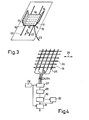
- Fig. 3 shows a perspective view of the boundary body 14.
- the rectangular plate 15 and the boundary plates 17 have an extension in the longitudinal direction 21 of the patient table 13 of preferably about 10 cm, so that several lines of signal transmitters 19 are arranged on the boundary body 14 parallel to the examination plane can be net. This is necessary since several adjacent planes of the body are usually irradiated in succession.
- the line spacing of the signal transmitters 19 corresponds to the spacing of the planes to be irradiated.
- the body 4 patient thus does not need to be moved relative to the limiting body 14.
- the limiting body 14 must be adjustable in the longitudinal direction 21 of the patient table 13 so that different, widely spaced areas of the body can be scanned.
- plastic rails 22 are fixedly attached to the patient table 13, which lie in the longitudinal direction 21 and which engage in corresponding grooves made on the underside of the plate 15.
- the plastic rails are provided with a scale graduation in order to enable a reproducible setting of the limiting body 14 by the operating personnel.
- the electrical signals of the signal transmitters 19 are passed via a cable 23 to an electronic unit to be explained further below.
- the patient table 13 can also be designed such that it is interrupted in the area of the examination plane, so that the X-ray radiation is not additionally weakened by it.
- FIG. 4 An exemplary embodiment of the individual signal transmitters 19 is shown in FIG. 4. They are defined as points of intersection of parallel transverse 24 and longitudinal conductor tracks 25 which are at the same distance from one another and are perpendicular to one another.
- the transverse conductor tracks 24 run parallel to the examination plane and, like the longitudinal conductor tracks 25, are vapor-deposited on one side of a thin film made of plastic are kept at a distance by a thin, X-ray-permeable foam layer (not shown) in such a way that the vapor-coated sides of the foils face one another.
- the foam layer is provided with holes in the area of the crossing points (signal transmitter 19), so that when the signal transmitter 19 is subjected to pressure, a direct contact occurs between the transverse 24 and the longitudinal conductor tracks 25, which consist, for example, of an X-ray radiation which absorbs little metal.
- the transverse 24 and the longitudinal conductor tracks 25 which consist, for example, of an X-ray radiation which absorbs little metal.
- they can consist of aluminum sheets covered with a thin layer of gold.
- the foam layer can also be continuous and have a weak electrical conductivity, which increases significantly under pressure. Both embodiments of the foam layers allow a simple and inexpensive manufacture of signal transmitters 19.
- the location of the signal transmitters 19 on the plate 15 or on the boundary plates 17 is predetermined, so that to determine the location coordinates of the signal transmitters 19 which are actually touched by the body 4, their output signals are detected.
- the transverse conductor track 24, which is located in the examination plane (indicated by the arrow 26), is connected to a power supply, while the longitudinal conductor tracks 25 for the detection of (output) signals are continuously transmitted by one via the lines 23a and them connected analog multiplexer 27 can be read, which is controlled by a clock generator 28.
- the signals are amplified in an amplifier 29 and digitized in an analog-to-digital converter 30.
- the analog-to-digital converter 30 is a threshold amplifier.
- the digitized signals are then stored in a memory 31.
- the signal transmitters 19 arranged on the plate 15 there is therefore a simple association between the signals present on the longitudinal conductor tracks 25 and the location coordinates xi of the individual signal transmitters 19 lying on the K coordinate axis (FIG. 1).
- the yi coordinates of the signal transmitters 19 located on the plate 15 are all to be regarded as constant, since the foam layer is very thin. For example, they are all at the same distance from the surface of the patient table 13, the height of which is described by the spatial coordinate y.
- an angle sensor which consists of a flexible and curved plastic rod 33, which is mounted in movable bearings 34, 35. Above and below the rod 33, a tensile or pressure-sensitive resistance element 36, 37 is glued on, which are connected together with two further (not shown) pressure-independent resistors to form an electrical resistance bridge W.
- a limiting plate 17 is rotated about an axis 16, the rod 33 is subjected to bending. The tensile or compressive forces on its top or bottom cause a change in the resistance of the elements 36, 37 and thus a detuning of the resistance bridge W.
- the angle-dependent electrical signals generated are passed to an amplifier and analog-digital converter 39.
- the relationship between the resistance detuning and the angle a is stored in a memory 40.
- the computing unit 41 calculates the corresponding angle-dependent coordinates x i ( ⁇ ), y i ( ⁇ ) from the positions of those signal transmitters 19 which are located on the boundary plates 17 and the angle a and stored in the memory 31 (FIG. 4).
- a memory 42 are then both the coordinates x i , y i of the signal transmitters 19 arranged on the plate 15 and the coordinates x i ( ⁇ ), y i ( ⁇ ) of the signal transmitters 19 arranged on the boundary plates 17 are stored.
- a thick, for example 5 cm thick, almost X-ray transparent and weakly conductive foam layer can be used, which is located between the transverse 24 or longitudinal conductor tracks 25.
- this foam layer is compressed to a greater or lesser extent at various locations in the examination plane, in such a way that it conforms to the body 4 in wide areas.
- Their electrical conductivity increases at the compressed points, so that the signal transmitters 19 acted upon by the body 4 generate output signals which depend on the compression of the foam layer or on the distance of its deformed surface from a reference system, for example the patient table 13.
- the coordinates x i , y i of the signal generator 19 on the plate 15 and the coordinates x i ( ⁇ ), y i ( ⁇ ) of those on the delimiting bodies 17 must then be corrected accordingly.
- the relationship between the compression of the foam layer (or the distance of its surface from the table top 13) and its electrical conductivity is stored in a memory 32 (FIG. 4).
- the digital output values of the analog-digital converter 30, which are pressure-dependent, are then used in addition for addressing in the memory 32, the distance found under each address also being stored in the memory 31.
- a first arithmetic unit 47 searches for each of the coordinates x i , y i , x i ( ⁇ ), y i ( ⁇ ) of the signal transmitters 19 touched by the body 4 for each of the coordinates x i , y i , x i ( ⁇ ), y i ( ⁇ ) and the beam paths 11 passing through them 11 belonging absorption values Q (p, ⁇ ), which are stored in the data memory 44.
- a second arithmetic unit 48 calculates the quotients L (p, ⁇ ) and from this boundary points 20 of the body 4 from these absorptim values Q (p, ⁇ ), as already described.
- edge points 20 are determined in order to achieve a uniform occupancy with them along the body edge.
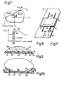
- the edge of the body 4 as shown in Fig. 7, is described by polar coordinates (r, ⁇ ).
- the center of the polar coordinate system coincides with the origin of the coordinate system XY. 7, a beam path 11 runs, for example, through the coordinates x i ( ⁇ ), y i ( ⁇ ) of a signal transmitter 19 touched by the body 4, an edge point P (r, cp) of the body 4 being defined on the beam path 11, whose distance from the signal generator 19 corresponds to the quotient L (p, #).
- improved edge points 52 are determined by averaging the edge points 20 (FIG. 8) located in individual, limited angular sections ⁇ ⁇ over the entire angular range nach according to known methods.
- the extension of the angular sections is, for example, 1 degree.
- a fifth computing unit 51 shown in FIG. 6 uses the determined edge of the body 4 in the manner described at the beginning to create the absorption data.
- Q (p, ⁇ ) which are also fed to the data memory 44 in order to determine a reconstruction image of the examination area 10.
- FIG. 9 shows a section lying in the examination plane through a limiting body 14 which can be arranged on the patient table 13 in a defined manner and is shown in the unloaded state. It is made almost from X-ray transparent plastic and consists of a thin, rectangular support plate 53 with two rectangular side plates 54, which are arranged on the support plate 53 on opposite sides about a respective axis 55. The axes 55 run perpendicular to the examination plane, which represents the drawing plane.
- the limiting body 14 is covered with a flexible film 56, a liquid 57 being located between the film 56 and the limiting body -14, the absorption coefficient of which corresponds to the average absorption coefficient of the body 4 (FIG. 10). Water is preferably used as the liquid 57.
- the film 56 is biased so that it has approximately a pillow-like cross section.
- a body 4 to be examined lies on the limiting body 14.
- the side plates 54 are pressed against the body 4 as far as possible, for example with the aid of springs 58.
- the film 56 nestles against the body 4, the liquid 57 being able to flow into an expansion tank 59 (FIG. 11) which is not in the X-ray range.
- the liquid 57 and the body 4 now form an almost uniform, composite examination body for the X-rays, which clings closely to the limiting body 14. Since the course of the delimitation body 14 is provided in the examination plane, the angle a between the side plates 54 and the support plate 53 is determined in the manner already described in FIG. 5, all points on the delimitation body are as contact points x iv y i or x i ( ⁇ ), y i ( ⁇ ). This makes it possible to determine a considerably larger number of edge points 20 of the body 4 in the manner already described.
- FIG. 11 shows a perspective view of the delimitation body 14. It has a longitudinal extent of preferably 40 cm, a central region of 30 cm being provided for use in the examination plane. This is necessary if several parallel layers of the body 4 are irradiated in succession without it having to be rearranged in between.
- the limiting body 14 is also adjustable in the longitudinal direction 21.
- plastic rails 60 are fixedly mounted on the patient table 13, on which the limiting body 14, which has corresponding grooves, slides.
- the rails 60 are provided with a scale graduation in order to enable a reproducible setting of the limiting body 14.
- the geometry of the limiting body 14 can also be adapted to the cross section of the body 4 lying in the examination plane and e.g. be bowl-shaped so that a limiting body 14 is obtained without moving parts (e.g. side plates 54).
- the devices according to the invention are also suitable for other X-ray tomography arrangements, for example for those which, in contrast to FIG. 1, have fixedly arranged, lying in the examination plane and the examination area e.g. circular detectors are provided.
Landscapes
- Health & Medical Sciences (AREA)
- Life Sciences & Earth Sciences (AREA)
- Engineering & Computer Science (AREA)
- Medical Informatics (AREA)
- Physics & Mathematics (AREA)
- Pathology (AREA)
- Veterinary Medicine (AREA)
- Biophysics (AREA)
- Public Health (AREA)
- General Health & Medical Sciences (AREA)
- Animal Behavior & Ethology (AREA)
- Surgery (AREA)
- Molecular Biology (AREA)
- Heart & Thoracic Surgery (AREA)
- Biomedical Technology (AREA)
- Radiology & Medical Imaging (AREA)
- Optics & Photonics (AREA)
- Nuclear Medicine, Radiotherapy & Molecular Imaging (AREA)
- High Energy & Nuclear Physics (AREA)
- Theoretical Computer Science (AREA)
- General Physics & Mathematics (AREA)
- Pulmonology (AREA)
- Dentistry (AREA)
- Oral & Maxillofacial Surgery (AREA)
- Apparatus For Radiation Diagnosis (AREA)
- Analysing Materials By The Use Of Radiation (AREA)
- Length-Measuring Devices Using Wave Or Particle Radiation (AREA)
Applications Claiming Priority (2)
| Application Number | Priority Date | Filing Date | Title |
|---|---|---|---|
| DE19782844927 DE2844927A1 (de) | 1978-10-14 | 1978-10-14 | Verfahren zur ermittlung des koerperrandes zur rekonstruktion einer absorptionsverteilung in einem ebenen untersuchungsbereich eines koerpers |
| DE2844927 | 1978-10-14 |
Publications (1)
| Publication Number | Publication Date |
|---|---|
| EP0010797A1 true EP0010797A1 (fr) | 1980-05-14 |
Family
ID=6052268
Family Applications (1)
| Application Number | Title | Priority Date | Filing Date |
|---|---|---|---|
| EP79200578A Withdrawn EP0010797A1 (fr) | 1978-10-14 | 1979-10-10 | Procédé et dispositifs de détermination du contour d'un corps pour reconstituer le degré d'absorption dans un plan passant par ce corps |
Country Status (6)
| Country | Link |
|---|---|
| US (1) | US4303829A (fr) |
| EP (1) | EP0010797A1 (fr) |
| JP (1) | JPS5552745A (fr) |
| BR (1) | BR7906587A (fr) |
| DD (1) | DD146507A5 (fr) |
| DE (1) | DE2844927A1 (fr) |
Cited By (5)
| Publication number | Priority date | Publication date | Assignee | Title |
|---|---|---|---|---|
| EP0022299A1 (fr) * | 1979-07-06 | 1981-01-14 | Koninklijke Philips Electronics N.V. | Procédé et dispositif pour déterminer la répartition de l'absorption de la radiation dans un plan d'un corps |
| FR2640394A1 (fr) * | 1988-12-14 | 1990-06-15 | Schlumberger Etienne | Procede pour coordonner plusieurs images d'un meme objet et dispositif pour sa mise en oeuvre |
| EP0443174A1 (fr) * | 1989-12-21 | 1991-08-28 | Lunar Corporation | Dispositif et procédé destinés au positionnement d'un patient |
| US5276613A (en) * | 1988-12-14 | 1994-01-04 | Etienne Schlumberger | Process and device for coordinating several images of the same object |
| FR2728775A1 (fr) * | 1994-12-29 | 1996-07-05 | Alain Buguet | Dispositif portable de detection et d'enregistrement de mouvement de personnes allongees ou d'animaux |
Families Citing this family (8)
| Publication number | Priority date | Publication date | Assignee | Title |
|---|---|---|---|---|
| US4969110A (en) * | 1988-08-01 | 1990-11-06 | General Electric Company | Method of using a priori information in computerized tomography |
| JPH02246936A (ja) * | 1989-03-22 | 1990-10-02 | Toshiba Corp | X線ct用寝台装置 |
| EP0445330A1 (fr) * | 1990-03-07 | 1991-09-11 | Siemens Aktiengesellschaft | Appareil médical dont une partie est positionnée par rapport à un plan, par asservissement selon au moins un degré de liberté |
| FR2702059B1 (fr) * | 1993-02-25 | 1995-09-15 | Berneuil Gerard | Procede d'amelioration de la qualite des cliches radiologiques et dispositif permettant la mise en oeuvre du procede. |
| JPH06267180A (ja) * | 1993-08-30 | 1994-09-22 | Matsushita Electric Ind Co Ltd | 記録再生装置 |
| US5764721A (en) * | 1997-01-08 | 1998-06-09 | Southwest Research Institute | Method for obtaining optimized computed tomography images from a body of high length-to-width ratio using computer aided design information for the body |
| WO2004107269A1 (fr) * | 2003-05-27 | 2004-12-09 | Clean Earth Technologies, Llc | Procede de reconstruction d'image rapide par source de rayonnements compacts et agencement de detecteurs utilisant la tomographie informatisee |
| CN100444799C (zh) * | 2005-08-18 | 2008-12-24 | Ge医疗系统环球技术有限公司 | 检查床位置测量方法、下垂补偿方法和x射线ct设备 |
Citations (5)
| Publication number | Priority date | Publication date | Assignee | Title |
|---|---|---|---|---|
| DE1949765B2 (de) * | 1969-10-02 | 1973-03-15 | Siemens AG, 1000 Berlin u. 8000 München | Patientenhalterungsvorrichtung |
| CH537734A (de) * | 1971-11-03 | 1973-06-15 | Bbc Brown Boveri & Cie | Lagerungsgerät für Patienten |
| DE2439847B2 (de) * | 1973-08-18 | 1979-04-12 | Emi Ltd., Hayes, Middlesex (Grossbritannien) | Medizinisches radiographisches Gerät zur Untersuchung von Querschnittsscheiben des Körpers eines Patienten |
| DE2802593A1 (de) * | 1978-01-21 | 1979-07-26 | Philips Patentverwaltung | Geraet zur ermittlung der raeumlichen verteilung der absorption von strahlung in einem ebenen bereich |
| DE2503978B2 (de) * | 1974-01-31 | 1980-05-08 | Emi Ltd., Hayes (Ver. Koenigreich) | Vorrichtung zur Untersuchung eines Körpers mit durchdringender Strahlung |
Family Cites Families (2)
| Publication number | Priority date | Publication date | Assignee | Title |
|---|---|---|---|---|
| GB1530621A (en) * | 1975-02-08 | 1978-11-01 | Emi Ltd | Radiography |
| GB1578754A (en) * | 1976-03-25 | 1980-11-12 | Emi Ltd | Patient positioning and supporting arrangement |
-
1978
- 1978-10-14 DE DE19782844927 patent/DE2844927A1/de not_active Withdrawn
-
1979
- 1979-10-09 US US06/083,195 patent/US4303829A/en not_active Expired - Lifetime
- 1979-10-10 EP EP79200578A patent/EP0010797A1/fr not_active Withdrawn
- 1979-10-11 BR BR7906587A patent/BR7906587A/pt unknown
- 1979-10-11 DD DD79216182A patent/DD146507A5/de unknown
- 1979-10-15 JP JP13196479A patent/JPS5552745A/ja active Pending
Patent Citations (5)
| Publication number | Priority date | Publication date | Assignee | Title |
|---|---|---|---|---|
| DE1949765B2 (de) * | 1969-10-02 | 1973-03-15 | Siemens AG, 1000 Berlin u. 8000 München | Patientenhalterungsvorrichtung |
| CH537734A (de) * | 1971-11-03 | 1973-06-15 | Bbc Brown Boveri & Cie | Lagerungsgerät für Patienten |
| DE2439847B2 (de) * | 1973-08-18 | 1979-04-12 | Emi Ltd., Hayes, Middlesex (Grossbritannien) | Medizinisches radiographisches Gerät zur Untersuchung von Querschnittsscheiben des Körpers eines Patienten |
| DE2503978B2 (de) * | 1974-01-31 | 1980-05-08 | Emi Ltd., Hayes (Ver. Koenigreich) | Vorrichtung zur Untersuchung eines Körpers mit durchdringender Strahlung |
| DE2802593A1 (de) * | 1978-01-21 | 1979-07-26 | Philips Patentverwaltung | Geraet zur ermittlung der raeumlichen verteilung der absorption von strahlung in einem ebenen bereich |
Cited By (6)
| Publication number | Priority date | Publication date | Assignee | Title |
|---|---|---|---|---|
| EP0022299A1 (fr) * | 1979-07-06 | 1981-01-14 | Koninklijke Philips Electronics N.V. | Procédé et dispositif pour déterminer la répartition de l'absorption de la radiation dans un plan d'un corps |
| FR2640394A1 (fr) * | 1988-12-14 | 1990-06-15 | Schlumberger Etienne | Procede pour coordonner plusieurs images d'un meme objet et dispositif pour sa mise en oeuvre |
| EP0374045A1 (fr) * | 1988-12-14 | 1990-06-20 | Etienne Schlumberger | Procédé pour coordonner plusieurs images d'un même objet et dispositif pour sa mise en oeuvre |
| US5276613A (en) * | 1988-12-14 | 1994-01-04 | Etienne Schlumberger | Process and device for coordinating several images of the same object |
| EP0443174A1 (fr) * | 1989-12-21 | 1991-08-28 | Lunar Corporation | Dispositif et procédé destinés au positionnement d'un patient |
| FR2728775A1 (fr) * | 1994-12-29 | 1996-07-05 | Alain Buguet | Dispositif portable de detection et d'enregistrement de mouvement de personnes allongees ou d'animaux |
Also Published As
| Publication number | Publication date |
|---|---|
| DE2844927A1 (de) | 1980-04-30 |
| US4303829A (en) | 1981-12-01 |
| BR7906587A (pt) | 1980-06-24 |
| DD146507A5 (de) | 1981-02-11 |
| JPS5552745A (en) | 1980-04-17 |
Similar Documents
| Publication | Publication Date | Title |
|---|---|---|
| EP0153786B1 (fr) | Appareil à rayons X | |
| EP1760457B1 (fr) | Procédé et dispositif destinés au calibrage d'un système de mesure | |
| EP0990892B1 (fr) | Méthode de tomographie assistée par ordinateur utilisant un faisceau cônique, et dispositif de tomographie | |
| DE102011004598B4 (de) | Verfahren und Computersystem zur Streustrahlkorrektur in einem Multi-Source-CT | |
| DE4238268C2 (de) | Verfahren und Vorrichtung zur Abnahme- und Konstanzprüfung filmloser Dental-Röntgengeräte | |
| DE2741958C2 (fr) | ||
| EP0035307B1 (fr) | Appareil de radiographie dentaire | |
| EP0496454A1 (fr) | Appareil de radiographie | |
| DE2842787C2 (de) | Computer-Tomograph | |
| DE2844927A1 (de) | Verfahren zur ermittlung des koerperrandes zur rekonstruktion einer absorptionsverteilung in einem ebenen untersuchungsbereich eines koerpers | |
| EP0057957B1 (fr) | Dispositif d'examen non médical d'un corps | |
| EP0037008A1 (fr) | Appareil de radiodiagnostic | |
| DE2831311C2 (de) | Vorrichtung zur Ermittlung innerer Körperstrukturen mittels Streustrahlung | |
| DE2721712C2 (de) | Computer-Tomograph | |
| DE2924423C2 (fr) | ||
| DE3904595C1 (en) | Device for determining the spatial coordinates of stereotactic target points by means of X-ray pictures | |
| DE2802593A1 (de) | Geraet zur ermittlung der raeumlichen verteilung der absorption von strahlung in einem ebenen bereich | |
| EP0436986B1 (fr) | Appareil d'examen d'un objet d'essai avec un rayonnement gamma ou X | |
| DE19964395B4 (de) | Rechnergestütztes Tomographieverfahren | |
| DE3021757C2 (fr) | ||
| DE2653465A1 (de) | Verfahren und vorrichtung fuer computer-tomographie | |
| DE3825830C2 (fr) | ||
| DE4216458C2 (de) | Verfahren zur Erfassung der Oberflächenform von Körpern | |
| DE4235183C2 (de) | Verfahren zur Erzeugung von Schichtaufnahmen von einem Meßobjekt mittels Röntgenstrahlung | |
| DE19603000A1 (de) | Verfahren zum Kalibrieren einer Anordnung zur Ermittlung des Impulsübertragsspektrums und Kalibriereinheit zur Durchführung des Verfahrens |
Legal Events
| Date | Code | Title | Description |
|---|---|---|---|
| PUAI | Public reference made under article 153(3) epc to a published international application that has entered the european phase |
Free format text: ORIGINAL CODE: 0009012 |
|
| AK | Designated contracting states |
Designated state(s): DE FR GB IT NL SE |
|
| 17P | Request for examination filed |
Effective date: 19801110 |
|
| STAA | Information on the status of an ep patent application or granted ep patent |
Free format text: STATUS: THE APPLICATION IS DEEMED TO BE WITHDRAWN |
|
| RAP1 | Party data changed (applicant data changed or rights of an application transferred) |
Owner name: N.V. PHILIPS' GLOEILAMPENFABRIEKEN Owner name: PHILIPS PATENTVERWALTUNG GMBH |
|
| 18D | Application deemed to be withdrawn |
Effective date: 19820701 |
|
| RIN1 | Information on inventor provided before grant (corrected) |
Inventor name: WAGNER, WOLFGANG |