EP0496454A1 - Appareil de radiographie - Google Patents
Appareil de radiographie Download PDFInfo
- Publication number
- EP0496454A1 EP0496454A1 EP92200113A EP92200113A EP0496454A1 EP 0496454 A1 EP0496454 A1 EP 0496454A1 EP 92200113 A EP92200113 A EP 92200113A EP 92200113 A EP92200113 A EP 92200113A EP 0496454 A1 EP0496454 A1 EP 0496454A1
- Authority
- EP
- European Patent Office
- Prior art keywords
- primary beam
- detector
- energy
- ray
- arrangement
- Prior art date
- Legal status (The legal status is an assumption and is not a legal conclusion. Google has not performed a legal analysis and makes no representation as to the accuracy of the status listed.)
- Granted
Links
Images


Classifications
-
- A—HUMAN NECESSITIES
- A61—MEDICAL OR VETERINARY SCIENCE; HYGIENE
- A61B—DIAGNOSIS; SURGERY; IDENTIFICATION
- A61B6/00—Apparatus or devices for radiation diagnosis; Apparatus or devices for radiation diagnosis combined with radiation therapy equipment
- A61B6/48—Diagnostic techniques
- A61B6/483—Diagnostic techniques involving scattered radiation
-
- A—HUMAN NECESSITIES
- A61—MEDICAL OR VETERINARY SCIENCE; HYGIENE
- A61B—DIAGNOSIS; SURGERY; IDENTIFICATION
- A61B6/00—Apparatus or devices for radiation diagnosis; Apparatus or devices for radiation diagnosis combined with radiation therapy equipment
- A61B6/02—Arrangements for diagnosis sequentially in different planes; Stereoscopic radiation diagnosis
- A61B6/03—Computed tomography [CT]
- A61B6/032—Transmission computed tomography [CT]
-
- A—HUMAN NECESSITIES
- A61—MEDICAL OR VETERINARY SCIENCE; HYGIENE
- A61B—DIAGNOSIS; SURGERY; IDENTIFICATION
- A61B6/00—Apparatus or devices for radiation diagnosis; Apparatus or devices for radiation diagnosis combined with radiation therapy equipment
- A61B6/42—Arrangements for detecting radiation specially adapted for radiation diagnosis
- A61B6/4208—Arrangements for detecting radiation specially adapted for radiation diagnosis characterised by using a particular type of detector
- A61B6/4241—Arrangements for detecting radiation specially adapted for radiation diagnosis characterised by using a particular type of detector using energy resolving detectors, e.g. photon counting
-
- G—PHYSICS
- G01—MEASURING; TESTING
- G01N—INVESTIGATING OR ANALYSING MATERIALS BY DETERMINING THEIR CHEMICAL OR PHYSICAL PROPERTIES
- G01N23/00—Investigating or analysing materials by the use of wave or particle radiation, e.g. X-rays or neutrons, not covered by groups G01N3/00 – G01N17/00, G01N21/00 or G01N22/00
- G01N23/20—Investigating or analysing materials by the use of wave or particle radiation, e.g. X-rays or neutrons, not covered by groups G01N3/00 – G01N17/00, G01N21/00 or G01N22/00 by using diffraction of the radiation by the materials, e.g. for investigating crystal structure; by using scattering of the radiation by the materials, e.g. for investigating non-crystalline materials; by using reflection of the radiation by the materials
- G01N23/201—Investigating or analysing materials by the use of wave or particle radiation, e.g. X-rays or neutrons, not covered by groups G01N3/00 – G01N17/00, G01N21/00 or G01N22/00 by using diffraction of the radiation by the materials, e.g. for investigating crystal structure; by using scattering of the radiation by the materials, e.g. for investigating non-crystalline materials; by using reflection of the radiation by the materials by measuring small-angle scattering
-
- G—PHYSICS
- G21—NUCLEAR PHYSICS; NUCLEAR ENGINEERING
- G21K—HANDLING OF PARTICLES OR IONISING RADIATION NOT OTHERWISE PROVIDED FOR; IRRADIATION DEVICES; GAMMA RAY OR X-RAY MICROSCOPES
- G21K1/00—Arrangements for handling particles or ionising radiation, e.g. focusing or moderating
- G21K1/02—Arrangements for handling particles or ionising radiation, e.g. focusing or moderating using diaphragms, collimators
- G21K1/025—Arrangements for handling particles or ionising radiation, e.g. focusing or moderating using diaphragms, collimators using multiple collimators, e.g. Bucky screens; other devices for eliminating undesired or dispersed radiation
Definitions
- the invention relates to an x-ray device with a polychromatic x-ray emitter for generating a primary beam with a small cross-section, an energy-resolving detector arrangement for detecting the scattered radiation generated by elastic scattering processes in the primary beam with a plurality of detector elements, which are arranged on rings concentric with the primary beam, and one between the x-ray emitter and arranged the collimator arrangement surrounding the primary beam.
- Such an X-ray device is essentially known from DE-OS 37 12 928.
- the collimator arrangement is designed so that the detector elements detect different sections of the primary beam within an examination area and that a slice of the scattering density can be produced if the examination area is irradiated by the primary beam in different directions and along parallel beam paths.
- an X-ray device is known with which the pulse transmission spectrum of a small area within a human body can be determined. Since the pulse transmission spectra of healthy and sick bones (affected by osteoporosis) differ significantly, such a procedure allows the condition of the bone substance to be assessed.
- the radiation scattered in the primary beam at a fixed scattering angle for example 3.5 °
- the pulse transmission determined according to the equation X sin (T / 2) / L, (1) where T is the scattering angle and L is the wavelength of the scattered radiation.
- the known device Since the scattering cross sections for elastic scattered radiation are relatively small, the known device has a comparatively low sensitivity, so that relatively large radiation doses are required for such examinations. Although it is possible to increase the radiation dose by increasing the predetermined angular range within which the scattered radiation is detected, the accuracy with which the pulse transmission can be determined is thereby reduced.
- the object of the present invention is to design an X-ray device of the type mentioned at the outset in such a way that the pulse transmission spectrum of a small volume range can be determined comparatively precisely within a large object with a relatively low dose.
- collimator arrangement is designed so that the scattered radiation from the same section of the primary beam strikes a plurality of detector elements.
- Each of the detector elements detects the scattered radiation under a relatively narrow scattering angle range, so that the pulse transmission spectrum can be determined relatively precisely with sufficient energy resolution of the individual detector elements. Since several detector elements detect the scattered radiation from the same section and since the pulse transmission spectrum is derived from the output signals of all these detector elements, the increase in sensitivity or the reduction in the radiation dose corresponds to the number of detector elements which "see" the same section of the primary beam.
- 1 denotes a polychromatic X-ray emitter, which can contain an X-ray tube, for example.
- the polychromatic X-ray emitter 1 emits X-radiation in an energy range which, in the case of an X-ray tube, depends on the high voltage applied to it.
- a needle beam (pencil beam) 3 ie a primary beam with a small cross section, is masked out by means of at least one pinhole 2 from the generated X-ray radiation.
- This primary beam passes through an extended object 4, for example a patient, which is supported on a table top 5.
- a detector arrangement D which measures the intensity of the primary beam and the scattered radiation generated in the primary beam.
- the detector arrangement measures the X-ray radiation in an energy-resolved manner, ie its output signals depend (linearly) on the energy of the respectively detected X-ray quanta.
- the detector arrangement D comprises a circular germanium crystal arranged concentrically to the primary beam 3 with a central detector element D0 and concentrically arranged ring-shaped detector elements D1..D7., Which independently detect the X-ray quanta.
- the central detector element D0 measures the intensity of the primary beam after passing through the body 4, while the detector elements D1..D7 separately detect the scattered radiation from the examination area.
- Each detector element is 2 mm wide and there is a gap of 0.5 mm between every two detector elements.
- the outermost detector element has an outer diameter of 70 mm.
- a collimator arrangement 6 is provided between the table top 5 and the detector arrangement D.
- This consists of a number of collimator lamellae, which have the shape of the shell of a truncated cone. The extensions of the lateral surfaces of these collimator lamellae intersect in the point 7 marked by a cross within the body 4.
- At least as many collimator lamellae are provided as detector elements, the arrangement being such that the scattered radiation between adjacent collimator lamellae is only applied to one of the detector elements D1 ..D7 can hit.
- the collimator lamellae consist of radiation-absorbing material, for example of 0.2 mm thick sheets of a copper / silver alloy.
- the height of the collimators is 300 mm, while the diameter of the outermost collimator (on its side facing the detector) is 70 mm. Point 7 is 500 mm away from the detector arrangement D.
- the impulse transmission spectrum of elastically scattered radiation depends essentially on the atomic composition of the body in which the scattered radiation is generated.
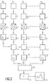
- Fig. 2 shows schematically the block diagram of an arrangement for determining the pulse transfer from the output signals of the detector. Then the central detector element D0 and each of the annular detector elements D1, D2..D7 is followed by an amplifier 10 or 11, 12..17, which amplifies the output signal of the associated detector element.
- the amplification factors of all amplifiers are preferably identical to one another.
- the amplitude of the output signal of the detector elements is proportional to the energy of the X-ray quantum that caused the relevant output signal.
- the amplitude of the output signals of the amplifiers 10..17 is therefore also proportional to the energy of the X-ray quanta.
- the analog output signals of the amplifiers 10 and 11, 12..17 are converted into digital output signals with the aid of analog-digital converters 20 and 21, 22..27 in such a way that for each X-ray quantum the one supplied by the digital-analog converter Digital value corresponds to the amplitude of the detector output signal.
- the digital-to-analog converters can each contain, for example, a capacitor which is charged via a peak value rectifier by the pulse-like output signal of the upstream amplifier and which is then completely discharged again by a constant current. The discharge duration is proportional to the energy of the X-ray quantum.
- the trigger signals for the digital-analog converter 20, 21..27 are derived from the output signals of the upstream detectors.
- the analog-to-digital converters 20 and 21, 22..27 together with the circuits 30 and 31, 32 .. 37 connected downstream of them form pulse height analyzers which register the frequency distribution of the amplitudes of the detector output signals. Since the amplitudes of the detector output signals are proportional to the energy of the X-ray quanta, the pulse height analyzers thus each supply the energy spectrum of the X-rays incident on the individual detector elements D0, D1..D7.
- the circuits 30 ... 37 can each contain a memory and an adder.
- the address corresponding to this data word is called up in the memory and the associated adder is activated. This adds a 1 to the content of the memory location called up and writes the result back to the relevant memory location, so that its content is increased by 1 in the result.
- the memory locations of each memory contain the number of X-ray quanta in the energy range assigned to this memory location, so that the energy spectrum for each detector element is stored separately in this way.
- the energy ranges in which the number of incident X-ray quanta is determined should be so finely divided that the accuracy with which the spectrum can be determined is determined only by the energy resolution of the detector elements. If, for example, the detector elements can reliably differentiate energy differences of 300 eV, the width of the individual energy areas in which registration is to be narrower than 300 eV. If the lowest energy to be registered is 30 keV and the highest is 130 keV, means this means that, for example, 500 (or 1000) energy ranges should be available and that a corresponding number of storage locations must be available in each pulse height analyzer.
- 3a, 3b, 3c the energy spectra - i.e. the number of X-ray quanta as a function of their energy - shown for different detector elements.
- FIG. 3a shows the energy spectrum E0 registered by the central detector element D0. This is determined on the one hand by the emission spectrum of the x-ray emitter and on the other hand by the energy dependence of the attenuation of the x-ray radiation by the object 4 (low-energy x-ray quanta are weakened more than high-energy ones).
- a distinctive line W can be seen, which is caused by the characteristic radiation of the X-ray emitter, and a (relative) minimum, which is caused by the absorption edge of the X-ray emitter. If the X-ray source contains a tungsten anode, the characteristic line W is approx. 59 keV and the absorption edge is approx. 69 keV.
- FIG. 3b shows the energy spectrum E6 of the X-ray quanta that strike the detector element D6.
- this spectrum also has two (relative) maxima F6 and B6, which are comparatively flat.
- the maximum F6 (at approx. 47 keV) is caused by the fat components in point 7 (Fig. 1), while the maximum B6 (at approx. 72 keV) results from the bone component.
- 3c shows the energy spectrum E7 of the detector element 7, which has a larger radius than the detector element 6 and thus receives the scattered radiation from point 7 at a larger scattering angle. Again, two maxima F7 and B7 are detectable, but these are shifted towards lower energies compared to the spectrum E6.
- the energy dependence of the radiation emitted by the X-ray emitter and the attenuation of the radiation by the examination object 4 must first be corrected.
- the fact is exploited that the scattered radiation that reaches the detector elements D1..D7, due to the comparatively small scattering angle (2-4 o ) are weakened by the examination object 4 in almost the same way as the primary beam 3, the intensity behind which Examination object is registered by the central detector element D0.
- the energy dependence of the radiation emitted by the X-ray emitter 1 also manifests itself in the primary beam in the same way as in the scattered radiation.
- the spectra E1..E are normalized to the spectrum E0 by dividing the number of X-ray quanta registered by the detector element in question by the number of X-ray quanta registered by the detector element D0 in the same energy range for each energy range, then the described energy dependency is eliminated - and at the same time any changes in the radiation dose registered during an examination behind the object.
- correction described is carried out with the aid of correction units 41, 42..47 which are connected downstream of the pulse height analyzers 21, 31..27, 37, in which each number which is in a memory location is one of the detector elements D1..D7 associated pulse height analyzer is stored, divided by the number that is stored in the circuit 30 in the memory location concerned.
- the correction units 41..47 can carry out further corrections, for example the correction of the background radiation.
- This background radiation is essentially caused by the collimators. It can be determined once by determining the energy spectrum of the scattered radiation when there is a model object in the primary beam 3 that does not fill point 7 and its immediate surroundings. It is saved and can be subtracted for the following measurements - expediently before normalization to the spectrum of the central detector.
- the corrected spectra E1 '.. E7' determined in this way are each stored in a memory 51, 52..57. They correspond to the spectrum that would result if the X-ray emitter emitted a "white" spectrum (with a constant intensity independent of the energy) and when only point 7 of the examination object 4 would be present in the beam path, but not the rest of the rest Part of the examination subject and not the collimator arrangement 6.
- the calculations according to equation (2) are carried out by a computer 18, for example a microcomputer.
- a computer 18 for example a microcomputer.
- the pulse transfer scale X is different with respect to the support points.
- the spread spectra are therefore only added after a conversion to uniform support points in the X scale carried out by means of interpolation.
- the addition of the spectra is carried out in a weighted manner with weightings previously determined empirically once. It is generally necessary to take into account the different quality of the individual spectra.
- the pulse spectrum determined in this way is stored in a register 19 and is thus available for further evaluation. It can be played back on a suitable display unit 28.
- FIG. 3d shows an example of such a pulse transmission spectrum.
- a pulse transmission spectrum can result if the examination point 7 is located in the cancellous bone substance, preferably the spine.
- This pulse transmission spectrum shows a maximum F (at approx. 1.2 / nm), which comes from the fat portion in point 7, and a maximum B, which comes from the bone portion and is approx. 1.8 / nm.
- the quotient from B and F or from the areas below B and F is a good measure of the mineral content or the strength of a bone. The higher this quotient, the better the condition of the bone tissue.
- the microcomputer 18 can also perform other functions, for example the correction of the energy spectra.
- the correction circuits 41..47 would be replaced by appropriate programming of the microcomputer.
- each of the detector rings D1..D7 would have to be divided into several - e.g. eight - arcuate segments, with a higher number of processing channels (e.g. 11..51) should be available.
- a correspondingly divided detector ring is shown in Fig. 1b.
- diametrically opposite segments are usually exposed to the same scattering intensity, these circuits would only be required for two segments each.
- an aperture could also be arranged in front of the detector D, which leaves only two opposite sectors of the rings free, so that scattered radiation can only be measured in these sectors.
- the aperture could then be rotated so that other sectors would be struck by stray radiation.
- the dose supplied to the examination object 4 is increased; however, the number of processing channels would be smaller than in the case of detector elements divided according to FIG. 1b.
Landscapes
- Health & Medical Sciences (AREA)
- Life Sciences & Earth Sciences (AREA)
- Engineering & Computer Science (AREA)
- Medical Informatics (AREA)
- Physics & Mathematics (AREA)
- General Health & Medical Sciences (AREA)
- High Energy & Nuclear Physics (AREA)
- Pathology (AREA)
- Surgery (AREA)
- Public Health (AREA)
- Optics & Photonics (AREA)
- Biophysics (AREA)
- Radiology & Medical Imaging (AREA)
- Biomedical Technology (AREA)
- Heart & Thoracic Surgery (AREA)
- Molecular Biology (AREA)
- Veterinary Medicine (AREA)
- Animal Behavior & Ethology (AREA)
- Nuclear Medicine, Radiotherapy & Molecular Imaging (AREA)
- Chemical & Material Sciences (AREA)
- Biochemistry (AREA)
- Toxicology (AREA)
- General Engineering & Computer Science (AREA)
- Crystallography & Structural Chemistry (AREA)
- Analytical Chemistry (AREA)
- Spectroscopy & Molecular Physics (AREA)
- General Physics & Mathematics (AREA)
- Immunology (AREA)
- Pulmonology (AREA)
- Theoretical Computer Science (AREA)
- Analysing Materials By The Use Of Radiation (AREA)
- Apparatus For Radiation Diagnosis (AREA)
Applications Claiming Priority (2)
| Application Number | Priority Date | Filing Date | Title |
|---|---|---|---|
| DE4101544 | 1991-01-19 | ||
| DE4101544A DE4101544A1 (de) | 1991-01-19 | 1991-01-19 | Roentgengeraet |
Publications (2)
| Publication Number | Publication Date |
|---|---|
| EP0496454A1 true EP0496454A1 (fr) | 1992-07-29 |
| EP0496454B1 EP0496454B1 (fr) | 1999-04-21 |
Family
ID=6423343
Family Applications (1)
| Application Number | Title | Priority Date | Filing Date |
|---|---|---|---|
| EP92200113A Expired - Lifetime EP0496454B1 (fr) | 1991-01-19 | 1992-01-16 | Appareil de radiographie |
Country Status (4)
| Country | Link |
|---|---|
| US (1) | US5265144A (fr) |
| EP (1) | EP0496454B1 (fr) |
| JP (1) | JPH04317633A (fr) |
| DE (2) | DE4101544A1 (fr) |
Cited By (2)
| Publication number | Priority date | Publication date | Assignee | Title |
|---|---|---|---|---|
| EP0643289A1 (fr) * | 1993-09-15 | 1995-03-15 | Philips Patentverwaltung GmbH | Procédé d'inspection pour évaluer des spectres dépendant de la localisation |
| WO2008142448A3 (fr) * | 2007-05-17 | 2009-01-15 | Durham Scient Crystals Ltd | Procédé et appareil pour l'inspection de matériaux |
Families Citing this family (64)
| Publication number | Priority date | Publication date | Assignee | Title |
|---|---|---|---|---|
| DE4445876B4 (de) * | 1994-12-22 | 2005-08-04 | Philips Intellectual Property & Standards Gmbh | Anordnung zum Messen des Impulsübertragsspektrums von elastisch gestreuten Röntgenquanten |
| GB2297835A (en) * | 1995-02-08 | 1996-08-14 | Secr Defence | Three dimensional detection of contraband using x rays |
| DE19504952B4 (de) * | 1995-02-15 | 2005-06-23 | Philips Intellectual Property & Standards Gmbh | Anordnung zum Messen von in einem Untersuchungsbereich elastisch gestreuten Röntgenquanten |
| JP3662352B2 (ja) * | 1996-07-19 | 2005-06-22 | ジーイー横河メディカルシステム株式会社 | X線ct装置 |
| RU2119660C1 (ru) * | 1997-04-08 | 1998-09-27 | Закрытое акционерное общество "Кванта Инвест" | Устройство для определения состава и структуры неоднородного объекта (варианты) |
| JP2000512764A (ja) * | 1997-01-24 | 2000-09-26 | クウォンタ・ビジョン・インコーポレイテッド | 物体の内部構造及び組成を判定する際に小角トポグラフィ的方法を用いる検査装置 |
| US6118850A (en) * | 1997-02-28 | 2000-09-12 | Rutgers, The State University | Analysis methods for energy dispersive X-ray diffraction patterns |
| US6054712A (en) * | 1998-01-23 | 2000-04-25 | Quanta Vision, Inc. | Inspection equipment using small-angle topography in determining an object's internal structure and composition |
| JP4289584B2 (ja) * | 1998-01-27 | 2009-07-01 | サーモ エレクトロン サイエンティフィック インスツルメンツ エルエルシー. | X線コリメータ、波長分散x線スペクトロメータ及びサンプル試料から放射するx線を検出する方法 |
| NL1008352C2 (nl) | 1998-02-19 | 1999-08-20 | Stichting Tech Wetenschapp | Inrichting, geschikt voor extreem ultraviolet lithografie, omvattende een stralingsbron en een verwerkingsorgaan voor het verwerken van de van de stralingsbron afkomstige straling, alsmede een filter voor het onderdrukken van ongewenste atomaire en microscopische deeltjes welke door een stralingsbron zijn uitgezonden. |
| EP1121584A4 (fr) | 1998-09-17 | 2002-10-16 | Noran Instr Inc | Application de l'optique des rayons x a la spectroscopie dispersive d'energie |
| US6542578B2 (en) | 1999-11-13 | 2003-04-01 | Heimann Systems Gmbh | Apparatus for determining the crystalline and polycrystalline materials of an item |
| DE19954663B4 (de) * | 1999-11-13 | 2006-06-08 | Smiths Heimann Gmbh | Verfahren und Vorrichtung zur Bestimmung eines Materials eines detektierten Gegenstandes |
| DE19954664B4 (de) * | 1999-11-13 | 2006-06-08 | Smiths Heimann Gmbh | Vorrichtung zur Bestimmung von kristallinen und polykristallinen Materialien eines Gegenstandes |
| DE19954662B4 (de) | 1999-11-13 | 2004-06-03 | Smiths Heimann Gmbh | Vorrichtung und Verfahren zum Detektieren von unzulässigen Reisegepäckgegenständen |
| GB2357414A (en) * | 1999-12-16 | 2001-06-20 | Secr Defence | Fast detection of X-rays using detector arrays and energy discrimination |
| ATE285576T1 (de) * | 2001-01-17 | 2005-01-15 | Yxlon Int Security Gmbh | Anordnung zum messen des impulsübertragungsspektrums von elastisch gestreuten röntgenquanten |
| ATE250761T1 (de) | 2001-03-14 | 2003-10-15 | Yxlon Int X Ray Gmbh | Anordnung zum messen des impulsübertragungsspektrums von in einem untersuchungsbereich für behältnisse elastisch gestreuten röntgenquanten |
| GB0201773D0 (en) * | 2002-01-25 | 2002-03-13 | Isis Innovation | X-ray diffraction method |
| US8243876B2 (en) | 2003-04-25 | 2012-08-14 | Rapiscan Systems, Inc. | X-ray scanners |
| US20050058242A1 (en) | 2003-09-15 | 2005-03-17 | Peschmann Kristian R. | Methods and systems for the rapid detection of concealed objects |
| GB0525593D0 (en) | 2005-12-16 | 2006-01-25 | Cxr Ltd | X-ray tomography inspection systems |
| US8837669B2 (en) | 2003-04-25 | 2014-09-16 | Rapiscan Systems, Inc. | X-ray scanning system |
| US8223919B2 (en) | 2003-04-25 | 2012-07-17 | Rapiscan Systems, Inc. | X-ray tomographic inspection systems for the identification of specific target items |
| US7949101B2 (en) | 2005-12-16 | 2011-05-24 | Rapiscan Systems, Inc. | X-ray scanners and X-ray sources therefor |
| US8451974B2 (en) | 2003-04-25 | 2013-05-28 | Rapiscan Systems, Inc. | X-ray tomographic inspection system for the identification of specific target items |
| US9113839B2 (en) | 2003-04-25 | 2015-08-25 | Rapiscon Systems, Inc. | X-ray inspection system and method |
| US7092485B2 (en) * | 2003-05-27 | 2006-08-15 | Control Screening, Llc | X-ray inspection system for detecting explosives and other contraband |
| GB0312499D0 (en) * | 2003-05-31 | 2003-07-09 | Council Cent Lab Res Councils | Tomographic energy dispersive diffraction imaging system |
| DE10333529A1 (de) * | 2003-07-23 | 2005-02-24 | Siemens Ag | Streustrahlenraster für eine Röntgendiagnostikeinrichtung |
| US7856081B2 (en) | 2003-09-15 | 2010-12-21 | Rapiscan Systems, Inc. | Methods and systems for rapid detection of concealed objects using fluorescence |
| US7366282B2 (en) * | 2003-09-15 | 2008-04-29 | Rapiscan Security Products, Inc. | Methods and systems for rapid detection of concealed objects using fluorescence |
| US20050117700A1 (en) * | 2003-08-08 | 2005-06-02 | Peschmann Kristian R. | Methods and systems for the rapid detection of concealed objects |
| EP1758503A1 (fr) * | 2004-06-07 | 2007-03-07 | Philips Intellectual Property & Standards GmbH | Tomographe assiste par ordinateur a diffusion coherente |
| DE102004035943B4 (de) * | 2004-07-23 | 2007-11-08 | GE Homeland Protection, Inc., , Newark | Röntgencomputertomograph sowie Verfahren zur Untersuchung eines Prüfteils mit einem Röntgencomputertomographen |
| GB0420222D0 (en) * | 2004-09-11 | 2004-10-13 | Koninkl Philips Electronics Nv | Coherent scatter imaging |
| GB0425112D0 (en) * | 2004-11-13 | 2004-12-15 | Koninkl Philips Electronics Nv | Computer tomography apparatus and method for examining an object of interest |
| DE102004060609A1 (de) * | 2004-12-16 | 2006-06-29 | Yxlon International Security Gmbh | Verfahren zum Messen des Impulsübertragungsspektrums von elastisch gestreuten Röntgenquanten |
| DE102004060611B4 (de) * | 2004-12-16 | 2007-02-22 | Yxlon International Security Gmbh | Anordnung zum Messen des Impulsübertragungsspektrums von elastisch gestreuten Röntgenquanten |
| GB0500535D0 (en) | 2005-01-12 | 2005-02-16 | Koninkl Philips Electronics Nv | Computer tomography apparatus |
| DE112006001584T5 (de) * | 2005-06-16 | 2008-05-29 | Ii-Vi Inc. | Energie unterscheidendes Streuabbildungssystem |
| US7697664B2 (en) * | 2006-05-15 | 2010-04-13 | Morpho Detection, Inc. | Systems and methods for determining an atomic number of a substance |
| US7587026B2 (en) * | 2006-05-15 | 2009-09-08 | General Electric Company | Systems and methods for determining a packing fraction of a substance |
| US7529340B2 (en) * | 2006-05-15 | 2009-05-05 | General Electric Company | Systems and methods for identifying a substance |
| DE102007045798B4 (de) * | 2007-09-25 | 2010-12-02 | Fraunhofer-Gesellschaft zur Förderung der angewandten Forschung e.V. | Anordnung und Verfahren zur Aufnahme von Röntgenstrahlen-Streuungsbildern |
| GB0823093D0 (en) * | 2008-12-19 | 2009-01-28 | Durham Scient Crystals Ltd | Apparatus and method for characterisation of materials |
| US9310323B2 (en) | 2009-05-16 | 2016-04-12 | Rapiscan Systems, Inc. | Systems and methods for high-Z threat alarm resolution |
| CN104170051B (zh) | 2012-02-03 | 2017-05-31 | 拉皮斯坎系统股份有限公司 | 组合散射和透射的多视图成像系统 |
| US9823383B2 (en) | 2013-01-07 | 2017-11-21 | Rapiscan Systems, Inc. | X-ray scanner with partial energy discriminating detector array |
| AU2014212158B2 (en) | 2013-01-31 | 2017-04-20 | Rapiscan Systems, Inc. | Portable security inspection system |
| CN105612416B (zh) * | 2013-07-25 | 2019-01-01 | 模拟技术公司 | 对象内物品的衍射特征的生成 |
| US9557427B2 (en) | 2014-01-08 | 2017-01-31 | Rapiscan Systems, Inc. | Thin gap chamber neutron detectors |
| FR3023001B1 (fr) * | 2014-06-30 | 2025-01-17 | Commissariat Energie Atomique | Procede d'analyse d'un objet en deux temps utilisant un rayonnement en transmission puis un spectre en diffusion. |
| FR3023000B1 (fr) * | 2014-06-30 | 2016-07-29 | Commissariat Energie Atomique | Procede et systeme d'analyse d'un objet par diffractometrie utilisant un spectre en diffusion et un spectre en transmission |
| JP6271384B2 (ja) * | 2014-09-19 | 2018-01-31 | 株式会社東芝 | 検査装置 |
| US10345479B2 (en) | 2015-09-16 | 2019-07-09 | Rapiscan Systems, Inc. | Portable X-ray scanner |
| US9939393B2 (en) | 2015-09-28 | 2018-04-10 | United Technologies Corporation | Detection of crystallographic properties in aerospace components |
| FR3043247B1 (fr) * | 2015-10-30 | 2020-06-19 | Commissariat A L'energie Atomique Et Aux Energies Alternatives | Collimateur pour la spectrometrie de diffraction x, dispositif associe et son utilisation |
| JP7649240B2 (ja) * | 2018-11-30 | 2025-03-19 | アキュレイ インコーポレイテッド | マルチモーダル放射線機器および方法 |
| GB2585673B (en) * | 2019-07-10 | 2022-05-04 | The Nottingham Trent Univ | A sample inspection system |
| US12181422B2 (en) | 2019-09-16 | 2024-12-31 | Rapiscan Holdings, Inc. | Probabilistic image analysis |
| CN115598157B (zh) * | 2021-06-25 | 2025-04-11 | 中国兵器工业第五九研究所 | 一种基于阵列探测的短波长特征x射线衍射装置和方法 |
| GB2624599A (en) | 2021-10-01 | 2024-05-22 | Rapiscan Holdings Inc | Methods and systems for the concurrent generation of multiple substantially similar X-ray beams |
| CN119618117B (zh) * | 2024-12-11 | 2025-09-26 | 合肥工业大学 | 一种x射线测量光斑准直系统 |
Citations (3)
| Publication number | Priority date | Publication date | Assignee | Title |
|---|---|---|---|---|
| GB1463054A (en) * | 1972-11-28 | 1977-02-02 | Emi Ltd | Radiology |
| EP0209952A2 (fr) * | 1985-07-20 | 1987-01-28 | Philips Patentverwaltung GmbH | Procédé pour la mesure de la répartition spatiale de rayonnement X diffusé élastiquement ainsi que le dispositif pour la mise en oeuvre du procédé |
| US4825454A (en) * | 1987-12-28 | 1989-04-25 | American Science And Engineering, Inc. | Tomographic imaging with concentric conical collimator |
Family Cites Families (7)
| Publication number | Priority date | Publication date | Assignee | Title |
|---|---|---|---|---|
| US4203037A (en) * | 1977-08-01 | 1980-05-13 | University Of Pittsburgh | Collimated radiation apparatus |
| SE423458B (sv) * | 1980-09-10 | 1982-05-03 | Agne Larsson | Anordning vid en kamera innefattande en manghalskollimator |
| FR2576694B1 (fr) * | 1985-01-28 | 1987-05-29 | Gilles Karcher | Collimateur pour tomoscintigraphie |
| DE3712928A1 (de) * | 1987-04-16 | 1988-11-03 | Philips Patentverwaltung | Roentgengeraet zur bestimmung der ortsabhaengigkeit der streueigenschaften in einer schicht eines untersuchungsbereichs |
| JPH03120500A (ja) * | 1989-10-04 | 1991-05-22 | Toshiba Corp | 多孔コリメータ及びその製造方法 |
| US5007072A (en) * | 1988-08-03 | 1991-04-09 | Ion Track Instruments | X-ray diffraction inspection system |
| DE3909147A1 (de) * | 1988-09-22 | 1990-09-27 | Philips Patentverwaltung | Anordnung zur messung des impulsuebertrages |
-
1991
- 1991-01-19 DE DE4101544A patent/DE4101544A1/de not_active Withdrawn
-
1992
- 1992-01-15 US US07/821,511 patent/US5265144A/en not_active Expired - Lifetime
- 1992-01-16 JP JP4005998A patent/JPH04317633A/ja active Pending
- 1992-01-16 DE DE59209678T patent/DE59209678D1/de not_active Expired - Fee Related
- 1992-01-16 EP EP92200113A patent/EP0496454B1/fr not_active Expired - Lifetime
Patent Citations (3)
| Publication number | Priority date | Publication date | Assignee | Title |
|---|---|---|---|---|
| GB1463054A (en) * | 1972-11-28 | 1977-02-02 | Emi Ltd | Radiology |
| EP0209952A2 (fr) * | 1985-07-20 | 1987-01-28 | Philips Patentverwaltung GmbH | Procédé pour la mesure de la répartition spatiale de rayonnement X diffusé élastiquement ainsi que le dispositif pour la mise en oeuvre du procédé |
| US4825454A (en) * | 1987-12-28 | 1989-04-25 | American Science And Engineering, Inc. | Tomographic imaging with concentric conical collimator |
Cited By (3)
| Publication number | Priority date | Publication date | Assignee | Title |
|---|---|---|---|---|
| EP0643289A1 (fr) * | 1993-09-15 | 1995-03-15 | Philips Patentverwaltung GmbH | Procédé d'inspection pour évaluer des spectres dépendant de la localisation |
| WO2008142448A3 (fr) * | 2007-05-17 | 2009-01-15 | Durham Scient Crystals Ltd | Procédé et appareil pour l'inspection de matériaux |
| US7693261B2 (en) | 2007-05-17 | 2010-04-06 | Durham Scientific Crystals Limited | Method and apparatus for inspection of materials |
Also Published As
| Publication number | Publication date |
|---|---|
| JPH04317633A (ja) | 1992-11-09 |
| US5265144A (en) | 1993-11-23 |
| DE4101544A1 (de) | 1992-07-23 |
| DE59209678D1 (de) | 1999-05-27 |
| EP0496454B1 (fr) | 1999-04-21 |
Similar Documents
| Publication | Publication Date | Title |
|---|---|---|
| EP0496454B1 (fr) | Appareil de radiographie | |
| EP0153786B1 (fr) | Appareil à rayons X | |
| EP0571017B1 (fr) | Procédé de filtrage pour un système rayons X et agencement pour réaliser ledit procédé de filtrage | |
| EP0209952B1 (fr) | Procédé pour la mesure de la répartition spatiale de rayonnement X diffusé élastiquement ainsi que le dispositif pour la mise en oeuvre du procédé | |
| EP0360347B1 (fr) | Dispositif pour la mesure du spectre de transfert d'impulsions | |
| EP0364613B1 (fr) | Procédé de fonctionnement d un appareil de tomographie assisté par ordinateur | |
| DE102006023309A1 (de) | Verfahren und Vorrichtung zur Erkennung von Material mittels Schnellneutronen und eines kontinuierlichen spektralen Röntgenstrahles | |
| DE2323610A1 (de) | Verfahren und einrichtung zur untersuchung mittels roentgenstrahlen | |
| EP0028431A1 (fr) | Dispositif pour la mesure de la répartition de densité d'un rayonnement dispersé dans une zône plane à examiner | |
| DE102012204350B4 (de) | Verfahren zur Energie-Kalibrierung quantenzählender Röntgendetektoren in einem Dual-Source Computertomographen | |
| DE3633738A1 (de) | Radiologische untersuchungsgeraet | |
| DE102016207437B4 (de) | Spektralunabhängige Ermittlung von Kalkablagerungen in Blutgefäßen | |
| EP0259921A2 (fr) | Procédé pour formation en 2 dimensions des images de profil Compton | |
| DE102007058447A1 (de) | Röntgendetektor, Röntgengerät und Verfahren zur Erfassung einer Röntgenstrahlung | |
| DE2713581A1 (de) | Anordnung zur darstellung einer ebene eines koerpers mit gamma- oder roentgenstrahlung | |
| DE2702009A1 (de) | Radiographisches geraet | |
| DE2831038C2 (de) | Strahlendiagnostikgerät für die Erzeugung von Schichtbildern | |
| DE2831311C2 (de) | Vorrichtung zur Ermittlung innerer Körperstrukturen mittels Streustrahlung | |
| EP0217464B1 (fr) | Procédé pour la détermination de l'atténuation photonique dans un domaine d'un corps et dispositif pour la mise en oeuvre du procédé | |
| EP0065803B1 (fr) | Dispositif d'examen de rayons X | |
| DE3037169C2 (fr) | ||
| DE102004035943B4 (de) | Röntgencomputertomograph sowie Verfahren zur Untersuchung eines Prüfteils mit einem Röntgencomputertomographen | |
| DE2655230A1 (de) | Verfahren und einrichtung zur roentgen- und gammastreustrahlen-tomographie | |
| DE3035524A1 (de) | Streustrahlen-durchleuchtungsanordnung | |
| DE19603000A1 (de) | Verfahren zum Kalibrieren einer Anordnung zur Ermittlung des Impulsübertragsspektrums und Kalibriereinheit zur Durchführung des Verfahrens |
Legal Events
| Date | Code | Title | Description |
|---|---|---|---|
| PUAI | Public reference made under article 153(3) epc to a published international application that has entered the european phase |
Free format text: ORIGINAL CODE: 0009012 |
|
| AK | Designated contracting states |
Kind code of ref document: A1 Designated state(s): DE FR GB |
|
| 17P | Request for examination filed |
Effective date: 19930126 |
|
| 17Q | First examination report despatched |
Effective date: 19950608 |
|
| APAB | Appeal dossier modified |
Free format text: ORIGINAL CODE: EPIDOS NOAPE |
|
| APAC | Appeal dossier modified |
Free format text: ORIGINAL CODE: EPIDOS NOAPO |
|
| APAD | Appeal reference recorded |
Free format text: ORIGINAL CODE: EPIDOS REFNE |
|
| RAP3 | Party data changed (applicant data changed or rights of an application transferred) |
Owner name: KONINKLIJKE PHILIPS ELECTRONICS N.V. Owner name: PHILIPS PATENTVERWALTUNG GMBH |
|
| APAB | Appeal dossier modified |
Free format text: ORIGINAL CODE: EPIDOS NOAPE |
|
| GRAG | Despatch of communication of intention to grant |
Free format text: ORIGINAL CODE: EPIDOS AGRA |
|
| GRAH | Despatch of communication of intention to grant a patent |
Free format text: ORIGINAL CODE: EPIDOS IGRA |
|
| GRAH | Despatch of communication of intention to grant a patent |
Free format text: ORIGINAL CODE: EPIDOS IGRA |
|
| GRAA | (expected) grant |
Free format text: ORIGINAL CODE: 0009210 |
|
| AK | Designated contracting states |
Kind code of ref document: B1 Designated state(s): DE FR GB |
|
| PG25 | Lapsed in a contracting state [announced via postgrant information from national office to epo] |
Ref country code: FR Free format text: LAPSE BECAUSE OF FAILURE TO SUBMIT A TRANSLATION OF THE DESCRIPTION OR TO PAY THE FEE WITHIN THE PRESCRIBED TIME-LIMIT Effective date: 19990421 |
|
| REF | Corresponds to: |
Ref document number: 59209678 Country of ref document: DE Date of ref document: 19990527 |
|
| GBT | Gb: translation of ep patent filed (gb section 77(6)(a)/1977) |
Effective date: 19990610 |
|
| EN | Fr: translation not filed | ||
| RAP4 | Party data changed (patent owner data changed or rights of a patent transferred) |
Owner name: KONINKLIJKE PHILIPS ELECTRONICS N.V. Owner name: PHILIPS CORPORATE INTELLECTUAL PROPERTY GMBH |
|
| PLBE | No opposition filed within time limit |
Free format text: ORIGINAL CODE: 0009261 |
|
| STAA | Information on the status of an ep patent application or granted ep patent |
Free format text: STATUS: NO OPPOSITION FILED WITHIN TIME LIMIT |
|
| 26N | No opposition filed | ||
| REG | Reference to a national code |
Ref country code: GB Ref legal event code: 732E |
|
| REG | Reference to a national code |
Ref country code: GB Ref legal event code: IF02 |
|
| REG | Reference to a national code |
Ref country code: GB Ref legal event code: 732E |
|
| APAH | Appeal reference modified |
Free format text: ORIGINAL CODE: EPIDOSCREFNO |
|
| REG | Reference to a national code |
Ref country code: GB Ref legal event code: 732E |
|
| PGFP | Annual fee paid to national office [announced via postgrant information from national office to epo] |
Ref country code: DE Payment date: 20090302 Year of fee payment: 18 |
|
| PGFP | Annual fee paid to national office [announced via postgrant information from national office to epo] |
Ref country code: GB Payment date: 20090129 Year of fee payment: 18 |
|
| GBPC | Gb: european patent ceased through non-payment of renewal fee |
Effective date: 20100116 |
|
| PG25 | Lapsed in a contracting state [announced via postgrant information from national office to epo] |
Ref country code: DE Free format text: LAPSE BECAUSE OF NON-PAYMENT OF DUE FEES Effective date: 20100803 |
|
| PG25 | Lapsed in a contracting state [announced via postgrant information from national office to epo] |
Ref country code: GB Free format text: LAPSE BECAUSE OF NON-PAYMENT OF DUE FEES Effective date: 20100116 |