EP0010832A1 - Verfahren und Vorrichtung zur Sammlung und Aufbewahrung von Umweltgasen - Google Patents
Verfahren und Vorrichtung zur Sammlung und Aufbewahrung von Umweltgasen Download PDFInfo
- Publication number
- EP0010832A1 EP0010832A1 EP79301443A EP79301443A EP0010832A1 EP 0010832 A1 EP0010832 A1 EP 0010832A1 EP 79301443 A EP79301443 A EP 79301443A EP 79301443 A EP79301443 A EP 79301443A EP 0010832 A1 EP0010832 A1 EP 0010832A1
- Authority
- EP
- European Patent Office
- Prior art keywords
- sample
- sample bottle
- environmental gas
- bottle
- temperature
- Prior art date
- Legal status (The legal status is an assumption and is not a legal conclusion. Google has not performed a legal analysis and makes no representation as to the accuracy of the status listed.)
- Granted
Links
Images
Classifications
-
- G—PHYSICS
- G01—MEASURING; TESTING
- G01N—INVESTIGATING OR ANALYSING MATERIALS BY DETERMINING THEIR CHEMICAL OR PHYSICAL PROPERTIES
- G01N1/00—Sampling; Preparing specimens for investigation
- G01N1/02—Devices for withdrawing samples
- G01N1/22—Devices for withdrawing samples in the gaseous state
- G01N1/24—Suction devices
Definitions
- This invention relates to a method and apparatus for collecting and storing a sample of an environmental gas such as air.
- Air samples have also been gathered by utilizing a liquefied gas to condense the air inside a pre-cooled container.
- the air sample is then taken to a laboratory where the container is allowed to warm to ambient temperature thus revaporizing the liquid to the gaseous state.
- the gaseous sample is then passed through the required analyzer.
- This method has the disadvantage that a supply of liquefied gas must be available.
- the liquefied gas evaporates and enters the gas environment in the area where the sample is being taken thereby causing the sample to be contaminated.
- Another disadvantage of existing apparatus is that the sample is collected by simply opening and closing a valve and is thus unsuitable for obtaining an average sample over, for example, several hours.
- the present invention overcomes these prior art problems and provides a method and apparatus for collecting a contamination-free sample by utilizing a closed cycle cryogenic refrigerator to condense and store the sample to be subsequently analyzed and means to collect the sample at a constant rate.
- a method of collecting and storing a sample of an environmental gas characterized in that it comprises the steps of:
- said environmental gas is air, in which case the sample bottle is preferably maintained at a temperature above 65°K and below 73°K.
- collection is continued until the sample bottle is full.
- the sample bottle is constructed from a lightweight structural metal.
- the apparatus comprises separate inlet and outlet conduits, and said metering means comprises a gas metering orifice at or adjacent the inlet of said inlet conduit.
- said apparatus includes a cryogenic refrigerator.
- said sample bottle and a portion of said cooling means are surrounded by insulation.
- Such instalation is preferably a lightweight synthetic foam.
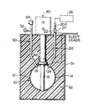
- the single figure of the drawing is a schematic representation of one embodiment of an apparatus in accordance with the present invention.
- numeral 10 indicates a sample bottle in the form of a sphere.
- the sample bottle 10 is fabricated in two hemispherical portions 12 and 14 and is supported by a post 16.
- the post 16 is fabricated from copper, which is a good heat conductor, and has on one end thereof an adaptor 18 for mating with a refrigerator as will be hereinafter more fully described.
- Outlet conduit 30 serves as a means for withdrawing collected sample and as a vent.
- Conduit 30 is similar to conduit 20, and is welded to the sample bottle 10. At the outlet end of conduit 30, there is a sample withdrawing valve 32 and a pressure relief valve 34.
- Refrigerator 40 is a single stage displacer- expander type refrigerator operated by a remote compressor and has a cold finger having, at its extremity, a cold shoe 42 which mates with adaptor 18 of post 16 to provide good thermal contact with the sample bottle 10.
- the major portions of the sample bottle 10, inlet conduit 20, outlet conduit 30, and the cold finger of the cryogenic refrigerator 40 are placed within a support housing 50 filled with synthetic foam 52 as insulation.
- the sample bottle 10 and conduits 20 and 30 are fabricated from stainless steel which is a relatively poor heat conductor.
- cryogenic refrigerator disclosed is preferable, however, it is not necessary that the cryogenic refrigerator be of the type utilizing a remote compressor. To do so only minimizes the weight of the overall system.
- the metering orifice 200 is installed in the inlet conduit 20 to set the rate at which the sample is drawn into the sample bottle 10.
- the apparatus shown in the drawing consists of a cryogenic refrigerator having a cold end (expander) separate from the compressor which can produce refrigeration at a temperature below 75° Kelvin (°K).
- the sample bottle 10 is sized to contain a specified quantity of the gas being sampled in liquid form.
- the apparatus is operated as follows. First, the sample bottle 10 is evacuated and, if necessary, heated to approximately 150°F to drive out contaminants. Depending upon the nature of insulation 52, it may have to be removed during the period when the sample bottle 10 is heated. If this is the case, after sample bottle 10 is cooled to ambient temperature, the insulation is replaced around the bottle. The cryogenic refrigerator 40 is then activated, and the system is allowed to cool down. As the system is cooled to below 75°K, the inlet shut-off valve 27 is opened causing a sample of the environment (e.g. air) to be drawn into the sample bottle 10 since it is partially evacuated. Sample bottle 10, being at a temperature below 75°K, will cause the air sample to condense and thus be stored as liquid within sample bottle 10. At the time the sample is to be analyzed, the system can be allowed to come to ambient temperature by turning off the cryogenic refrigerator 40, withdrawing the sample through valve 32, and putting the sample through an analyzer.
- a sample of the environment e.g. air
- the apparatus operates on the principal that below 78.8 0 K air, if this is the gas being sampled, liquefies.
- the sample bottle 10 cooled to this temperature, creates a partial vacuum in the bottle which permits the sample of ambient air to be drawn into the bottle and condense.
- the sample so collected is not contaminated since the bottle is clean to start with, and the sample has not passed through a compression device.
- the pressure in the sample bottle 10 is less than the critical pressure for the orifice, the flow rate of gas through the orifice into the bottle will be constant.
- the equation for the critical pressure is
- sample bottle 10 becomes full with liquid, and liquid begins to fill the inlet tube 20, the temperature of the surface of the liquid in inlet tube 20 rises to at least 78.8°K, thus equalizing the pressure in the inlet tube and thus prevents further sampling since the pressure in the inlet tube would be the same as upstream of the metering orifice 20.
- the system can be designed to be lightweight and portable with rapid cooldown, e.g. of the order of 30 minutes. It is possible when the refrigerator is turned off and the sample warms to have it boil off and flow directly into a gas analyzer without the need for intermediate containment and thus avoid further opportunities for contamination.
- a separate withdrawal/vent line provides an added safety feature.
- the internal post 16 provides a condensing surface for the sample and helps maintain a uniform temperature and provides internal structural support for the sample bottle 10.
- the inclusion of electrical leads can provide a mechanism for removing blockages in the event of a freeze-up in the system.
- the collected sample will remain liquefied. Until the sample container 10 is filled, there will be a partial vacuum within the sample container 10 thus continuing the collection process and the metering orifice 28 will continue to admit the sample at a constant rate in accordance with the orifice setting.
- the apparatus can be applied to sampling other gaseous atmospheres as long as the refrigerator is set to operate at temperature ranges that will maintain the sample in liquid form inside the bottle 10.
Landscapes
- Health & Medical Sciences (AREA)
- Life Sciences & Earth Sciences (AREA)
- Engineering & Computer Science (AREA)
- Biomedical Technology (AREA)
- Molecular Biology (AREA)
- Physics & Mathematics (AREA)
- Chemical & Material Sciences (AREA)
- Analytical Chemistry (AREA)
- Biochemistry (AREA)
- General Health & Medical Sciences (AREA)
- General Physics & Mathematics (AREA)
- Immunology (AREA)
- Pathology (AREA)
- Sampling And Sample Adjustment (AREA)
Applications Claiming Priority (2)
| Application Number | Priority Date | Filing Date | Title |
|---|---|---|---|
| US05/956,312 US4195524A (en) | 1978-10-31 | 1978-10-31 | Method and apparatus for collecting and storing environmental gases |
| US956312 | 2001-09-18 |
Publications (2)
| Publication Number | Publication Date |
|---|---|
| EP0010832A1 true EP0010832A1 (de) | 1980-05-14 |
| EP0010832B1 EP0010832B1 (de) | 1981-12-16 |
Family
ID=25498067
Family Applications (1)
| Application Number | Title | Priority Date | Filing Date |
|---|---|---|---|
| EP79301443A Expired EP0010832B1 (de) | 1978-10-31 | 1979-07-20 | Verfahren und Vorrichtung zur Sammlung und Aufbewahrung von Umweltgasen |
Country Status (5)
| Country | Link |
|---|---|
| US (1) | US4195524A (de) |
| EP (1) | EP0010832B1 (de) |
| JP (1) | JPS5560836A (de) |
| CA (1) | CA1094848A (de) |
| DE (1) | DE2961580D1 (de) |
Cited By (3)
| Publication number | Priority date | Publication date | Assignee | Title |
|---|---|---|---|---|
| EP0031148A3 (en) * | 1979-12-21 | 1982-04-14 | Air Products And Chemicals, Inc. | Cryogenic air sampler |
| GB2149102A (en) * | 1983-10-14 | 1985-06-05 | Robert C Mcfarland | Mixed gamma emitting gas standard and method |
| GB2157431A (en) * | 1984-04-12 | 1985-10-23 | Us Energy | Sub-micron particle sampler apparatus and method for sampling airbourne sub-micron particles |
Families Citing this family (15)
| Publication number | Priority date | Publication date | Assignee | Title |
|---|---|---|---|---|
| JPS5935714U (ja) * | 1982-08-31 | 1984-03-06 | アルプス電気株式会社 | ねじの取付構造 |
| US4998848A (en) * | 1989-03-27 | 1991-03-12 | R. G. Hansen & Associates | Method and apparatus for removing ground contaminants |
| US5066166A (en) * | 1989-03-27 | 1991-11-19 | R. G. Hansen & Associates | Apparatus for removing ground contaminants |
| DE4001979A1 (de) * | 1990-01-24 | 1991-07-25 | Kernforschungsz Karlsruhe | Verfahren und vorrichtung zur kontinuierlichen ueberwachung von abgasen aus verbrennungsanlagen |
| US5463909A (en) * | 1994-03-15 | 1995-11-07 | Minnesota Mining And Manufacturing Company | Runoff water sampler |
| US5700695A (en) * | 1994-06-30 | 1997-12-23 | Zia Yassinzadeh | Sample collection and manipulation method |
| US5461934A (en) * | 1994-12-20 | 1995-10-31 | Budd; Alexander G. | Ambient air collection device for use with a self-contained breathing apparatus |
| US5714696A (en) * | 1995-07-06 | 1998-02-03 | The Regents Of The University Of California | Fluid sampling apparatus and method |
| US5736404A (en) * | 1995-12-27 | 1998-04-07 | Zia Yassinzadeh | Flow detection appartus and method |
| US6880413B2 (en) * | 1999-12-30 | 2005-04-19 | Endress + Hauser Wetzer Gmbh + Co. Kg | Sampler and method of dispensing and cooling a fluid |
| US7354774B2 (en) * | 2002-05-13 | 2008-04-08 | Becton, Dickinson And Company | Self aliquoting sample storage plate |
| WO2006025910A1 (en) * | 2004-06-12 | 2006-03-09 | Auburn University | Cryogenic adsorption pump for the collection of airborne gases, particles, organic molecules and micro-organisms |
| MX2010008763A (es) * | 2008-02-11 | 2010-09-07 | Marc-Antonie Pelletier | Sistema y metodo de extraccion de gas y liquido. |
| US20110132083A1 (en) * | 2009-12-04 | 2011-06-09 | Linde Aktiengesellschaft | Low Temperature Gas Flow Sensor |
| CN115078511B (zh) * | 2021-03-11 | 2025-09-09 | 台湾积体电路制造股份有限公司 | 监测气态分子污染物的方法与系统 |
Citations (4)
| Publication number | Priority date | Publication date | Assignee | Title |
|---|---|---|---|---|
| US3295359A (en) * | 1963-11-20 | 1967-01-03 | Controlled Environment Equipme | Air sampler |
| US3866474A (en) * | 1973-06-25 | 1975-02-18 | Trw Inc | Gas sample collecting device |
| US3938391A (en) * | 1974-02-23 | 1976-02-17 | Linde Aktiengesellschaft | Sampling device for liquefied gases |
| DE1925883B2 (de) * | 1968-05-22 | 1977-03-24 | N.V. Philips' Gloeilampenfabrieken, Eindhoven (Niederlande) | Verfahren und anordnung zum analysieren von gasgemischen |
Family Cites Families (2)
| Publication number | Priority date | Publication date | Assignee | Title |
|---|---|---|---|---|
| FR1463891A (fr) * | 1965-09-21 | 1966-07-22 | Commissariat Energie Atomique | Dispositif de piégeage de gaz en haute atmosphère |
| JPS5246141U (de) * | 1975-09-29 | 1977-04-01 |
-
1978
- 1978-10-31 US US05/956,312 patent/US4195524A/en not_active Expired - Lifetime
-
1979
- 1979-07-10 CA CA331,483A patent/CA1094848A/en not_active Expired
- 1979-07-19 JP JP9210079A patent/JPS5560836A/ja active Granted
- 1979-07-20 DE DE7979301443T patent/DE2961580D1/de not_active Expired
- 1979-07-20 EP EP79301443A patent/EP0010832B1/de not_active Expired
Patent Citations (4)
| Publication number | Priority date | Publication date | Assignee | Title |
|---|---|---|---|---|
| US3295359A (en) * | 1963-11-20 | 1967-01-03 | Controlled Environment Equipme | Air sampler |
| DE1925883B2 (de) * | 1968-05-22 | 1977-03-24 | N.V. Philips' Gloeilampenfabrieken, Eindhoven (Niederlande) | Verfahren und anordnung zum analysieren von gasgemischen |
| US3866474A (en) * | 1973-06-25 | 1975-02-18 | Trw Inc | Gas sample collecting device |
| US3938391A (en) * | 1974-02-23 | 1976-02-17 | Linde Aktiengesellschaft | Sampling device for liquefied gases |
Cited By (3)
| Publication number | Priority date | Publication date | Assignee | Title |
|---|---|---|---|---|
| EP0031148A3 (en) * | 1979-12-21 | 1982-04-14 | Air Products And Chemicals, Inc. | Cryogenic air sampler |
| GB2149102A (en) * | 1983-10-14 | 1985-06-05 | Robert C Mcfarland | Mixed gamma emitting gas standard and method |
| GB2157431A (en) * | 1984-04-12 | 1985-10-23 | Us Energy | Sub-micron particle sampler apparatus and method for sampling airbourne sub-micron particles |
Also Published As
| Publication number | Publication date |
|---|---|
| DE2961580D1 (en) | 1982-02-11 |
| US4195524A (en) | 1980-04-01 |
| EP0010832B1 (de) | 1981-12-16 |
| JPS5720568B2 (de) | 1982-04-30 |
| JPS5560836A (en) | 1980-05-08 |
| CA1094848A (en) | 1981-02-03 |
Similar Documents
| Publication | Publication Date | Title |
|---|---|---|
| EP0010832B1 (de) | Verfahren und Vorrichtung zur Sammlung und Aufbewahrung von Umweltgasen | |
| CN106932228B (zh) | 天然六氟化铀液相取样系统及方法 | |
| JP2003515086A (ja) | 液体酸素の生成 | |
| JPH07506535A (ja) | 超臨界流体抽出装置及び方法 | |
| CN109946407A (zh) | 一种用于h同位素分析的矿物包裹体水样提取装置 | |
| EP0031148B1 (de) | Gekühlter Luftprobenentnehmer | |
| US3938391A (en) | Sampling device for liquefied gases | |
| US5205177A (en) | Method and apparatus for gas monitoring | |
| JPH0422623B2 (de) | ||
| CN113551154B (zh) | 一种在线式lng取样器 | |
| KR820001721B1 (ko) | 대기(大氣)를 포집, 저장하는 방법 | |
| EP0418352A1 (de) | Verfahren und vorrichtung zur bestimmung von feuchtigkeit in stoffen | |
| JPH09329533A (ja) | 非加水分解性気体用金属サンプリング方法およびシステム | |
| US3673871A (en) | Portable liquid gas sampler system | |
| CN117147745B (zh) | 一种液氢固空制备及测试装置及其方法 | |
| US4214473A (en) | Gaseous trace impurity analyzer and method | |
| CN105353046A (zh) | 一种挥发性有机物气体冷冻捕集系统及捕集方法 | |
| US3724169A (en) | Delta t bar spectrometer | |
| JP2533709Y2 (ja) | 低温液化ガス用ガス化サンプリング装置 | |
| US4100757A (en) | Closed circuit ammonia system for liquid heating from water | |
| JP3102507B2 (ja) | 飽和空気発生装置 | |
| JPH02174901A (ja) | 凝集トラップのガス流から微量物質を中間濃縮する装置 | |
| SU920439A1 (ru) | Криогенно-конденсационное устройство дл отбора проб воздуха с примес ми | |
| JP2653530B2 (ja) | トリチウム濃度測定装置 | |
| CN111059820B (zh) | 液态制冷方案吸收瓶采样制冷和低温存储复合装置及方法 |
Legal Events
| Date | Code | Title | Description |
|---|---|---|---|
| PUAI | Public reference made under article 153(3) epc to a published international application that has entered the european phase |
Free format text: ORIGINAL CODE: 0009012 |
|
| AK | Designated contracting states |
Designated state(s): DE FR GB |
|
| 17P | Request for examination filed | ||
| GRAA | (expected) grant |
Free format text: ORIGINAL CODE: 0009210 |
|
| AK | Designated contracting states |
Designated state(s): DE FR GB |
|
| REF | Corresponds to: |
Ref document number: 2961580 Country of ref document: DE Date of ref document: 19820211 |
|
| PGFP | Annual fee paid to national office [announced via postgrant information from national office to epo] |
Ref country code: FR Payment date: 19840620 Year of fee payment: 6 |
|
| PGFP | Annual fee paid to national office [announced via postgrant information from national office to epo] |
Ref country code: DE Payment date: 19840705 Year of fee payment: 6 |
|
| PG25 | Lapsed in a contracting state [announced via postgrant information from national office to epo] |
Ref country code: FR Free format text: LAPSE BECAUSE OF NON-PAYMENT OF DUE FEES Effective date: 19870331 |
|
| PG25 | Lapsed in a contracting state [announced via postgrant information from national office to epo] |
Ref country code: DE Effective date: 19870401 |
|
| GBPC | Gb: european patent ceased through non-payment of renewal fee | ||
| REG | Reference to a national code |
Ref country code: FR Ref legal event code: ST |
|
| PG25 | Lapsed in a contracting state [announced via postgrant information from national office to epo] |
Ref country code: GB Effective date: 19881118 |
|
| PLBE | No opposition filed within time limit |
Free format text: ORIGINAL CODE: 0009261 |
|
| STAA | Information on the status of an ep patent application or granted ep patent |
Free format text: STATUS: NO OPPOSITION FILED WITHIN TIME LIMIT |