EP0010908A1 - Appareil de réanimation cardiopulmonaire - Google Patents
Appareil de réanimation cardiopulmonaire Download PDFInfo
- Publication number
- EP0010908A1 EP0010908A1 EP79302275A EP79302275A EP0010908A1 EP 0010908 A1 EP0010908 A1 EP 0010908A1 EP 79302275 A EP79302275 A EP 79302275A EP 79302275 A EP79302275 A EP 79302275A EP 0010908 A1 EP0010908 A1 EP 0010908A1
- Authority
- EP
- European Patent Office
- Prior art keywords
- patient
- compressor
- heart
- cardiac
- pad
- Prior art date
- Legal status (The legal status is an assumption and is not a legal conclusion. Google has not performed a legal analysis and makes no representation as to the accuracy of the status listed.)
- Granted
Links
- 230000000747 cardiac effect Effects 0.000 title claims abstract description 59
- 210000002216 heart Anatomy 0.000 claims abstract description 79
- 230000006835 compression Effects 0.000 claims abstract description 36
- 238000007906 compression Methods 0.000 claims abstract description 36
- 238000012544 monitoring process Methods 0.000 claims abstract description 27
- 210000000038 chest Anatomy 0.000 claims abstract description 23
- 210000001562 sternum Anatomy 0.000 claims abstract description 21
- 230000000694 effects Effects 0.000 claims abstract description 19
- 230000001862 defibrillatory effect Effects 0.000 claims abstract description 16
- 210000004072 lung Anatomy 0.000 claims abstract description 12
- 238000007789 sealing Methods 0.000 claims description 8
- 239000002184 metal Substances 0.000 claims description 5
- 229910052751 metal Inorganic materials 0.000 claims description 5
- 238000003780 insertion Methods 0.000 claims description 3
- 230000037431 insertion Effects 0.000 claims description 3
- 229920005830 Polyurethane Foam Polymers 0.000 claims description 2
- 239000011496 polyurethane foam Substances 0.000 claims description 2
- 210000001584 soft palate Anatomy 0.000 claims description 2
- 210000000214 mouth Anatomy 0.000 claims 2
- 239000004020 conductor Substances 0.000 claims 1
- 210000003800 pharynx Anatomy 0.000 claims 1
- 230000001960 triggered effect Effects 0.000 claims 1
- 101100222276 Drosophila melanogaster cuff gene Proteins 0.000 description 28
- 230000035939 shock Effects 0.000 description 21
- QVGXLLKOCUKJST-UHFFFAOYSA-N atomic oxygen Chemical compound [O] QVGXLLKOCUKJST-UHFFFAOYSA-N 0.000 description 12
- 238000000034 method Methods 0.000 description 12
- 239000001301 oxygen Substances 0.000 description 12
- 229910052760 oxygen Inorganic materials 0.000 description 12
- 238000009120 supportive therapy Methods 0.000 description 8
- 238000009423 ventilation Methods 0.000 description 8
- 238000009110 definitive therapy Methods 0.000 description 7
- 208000003663 ventricular fibrillation Diseases 0.000 description 7
- 210000002784 stomach Anatomy 0.000 description 6
- 206010003119 arrhythmia Diseases 0.000 description 5
- 230000009467 reduction Effects 0.000 description 5
- 230000003319 supportive effect Effects 0.000 description 5
- PXHVJJICTQNCMI-UHFFFAOYSA-N Nickel Chemical compound [Ni] PXHVJJICTQNCMI-UHFFFAOYSA-N 0.000 description 4
- 230000006793 arrhythmia Effects 0.000 description 4
- 239000008280 blood Substances 0.000 description 4
- 210000004369 blood Anatomy 0.000 description 4
- 208000014674 injury Diseases 0.000 description 4
- 230000008733 trauma Effects 0.000 description 4
- 238000010276 construction Methods 0.000 description 3
- 229920001971 elastomer Polymers 0.000 description 3
- 239000000806 elastomer Substances 0.000 description 3
- 239000007789 gas Substances 0.000 description 3
- 210000004165 myocardium Anatomy 0.000 description 3
- 229920003023 plastic Polymers 0.000 description 3
- 239000004033 plastic Substances 0.000 description 3
- 208000010496 Heart Arrest Diseases 0.000 description 2
- BQCADISMDOOEFD-UHFFFAOYSA-N Silver Chemical compound [Ag] BQCADISMDOOEFD-UHFFFAOYSA-N 0.000 description 2
- 125000004122 cyclic group Chemical group 0.000 description 2
- 230000002496 gastric effect Effects 0.000 description 2
- 210000004051 gastric juice Anatomy 0.000 description 2
- PCHJSUWPFVWCPO-UHFFFAOYSA-N gold Chemical compound [Au] PCHJSUWPFVWCPO-UHFFFAOYSA-N 0.000 description 2
- 229910052737 gold Inorganic materials 0.000 description 2
- 239000010931 gold Substances 0.000 description 2
- 239000000463 material Substances 0.000 description 2
- 229910052759 nickel Inorganic materials 0.000 description 2
- 230000000737 periodic effect Effects 0.000 description 2
- 230000008569 process Effects 0.000 description 2
- 238000005086 pumping Methods 0.000 description 2
- 229910052709 silver Inorganic materials 0.000 description 2
- 239000004332 silver Substances 0.000 description 2
- 230000000472 traumatic effect Effects 0.000 description 2
- SUBDBMMJDZJVOS-UHFFFAOYSA-N 5-methoxy-2-{[(4-methoxy-3,5-dimethylpyridin-2-yl)methyl]sulfinyl}-1H-benzimidazole Chemical compound N=1C2=CC(OC)=CC=C2NC=1S(=O)CC1=NC=C(C)C(OC)=C1C SUBDBMMJDZJVOS-UHFFFAOYSA-N 0.000 description 1
- 229910001369 Brass Inorganic materials 0.000 description 1
- RYGMFSIKBFXOCR-UHFFFAOYSA-N Copper Chemical compound [Cu] RYGMFSIKBFXOCR-UHFFFAOYSA-N 0.000 description 1
- 241000238558 Eucarida Species 0.000 description 1
- 238000010420 art technique Methods 0.000 description 1
- 230000017531 blood circulation Effects 0.000 description 1
- 230000008081 blood perfusion Effects 0.000 description 1
- 239000010951 brass Substances 0.000 description 1
- 230000002612 cardiopulmonary effect Effects 0.000 description 1
- 238000002680 cardiopulmonary resuscitation Methods 0.000 description 1
- 230000003833 cell viability Effects 0.000 description 1
- 238000004891 communication Methods 0.000 description 1
- 229920001940 conductive polymer Polymers 0.000 description 1
- 230000008602 contraction Effects 0.000 description 1
- 230000001276 controlling effect Effects 0.000 description 1
- 229910052802 copper Inorganic materials 0.000 description 1
- 239000010949 copper Substances 0.000 description 1
- 230000000994 depressogenic effect Effects 0.000 description 1
- 229920002457 flexible plastic Polymers 0.000 description 1
- 229920005570 flexible polymer Polymers 0.000 description 1
- 239000012530 fluid Substances 0.000 description 1
- 238000011010 flushing procedure Methods 0.000 description 1
- 239000006260 foam Substances 0.000 description 1
- 210000003709 heart valve Anatomy 0.000 description 1
- 210000004124 hock Anatomy 0.000 description 1
- 239000013528 metallic particle Substances 0.000 description 1
- 238000012986 modification Methods 0.000 description 1
- 230000004048 modification Effects 0.000 description 1
- 210000004877 mucosa Anatomy 0.000 description 1
- 210000003205 muscle Anatomy 0.000 description 1
- 231100000344 non-irritating Toxicity 0.000 description 1
- 230000037361 pathway Effects 0.000 description 1
- 230000010412 perfusion Effects 0.000 description 1
- 229920000915 polyvinyl chloride Polymers 0.000 description 1
- 239000004800 polyvinyl chloride Substances 0.000 description 1
- 230000002035 prolonged effect Effects 0.000 description 1
- 230000001105 regulatory effect Effects 0.000 description 1
- 230000000241 respiratory effect Effects 0.000 description 1
- 230000029058 respiratory gaseous exchange Effects 0.000 description 1
- 230000004044 response Effects 0.000 description 1
- 230000000284 resting effect Effects 0.000 description 1
- 210000000614 rib Anatomy 0.000 description 1
- 230000002459 sustained effect Effects 0.000 description 1
- 229920003051 synthetic elastomer Polymers 0.000 description 1
- 239000005061 synthetic rubber Substances 0.000 description 1
- 238000012360 testing method Methods 0.000 description 1
- 210000004916 vomit Anatomy 0.000 description 1
- 230000008673 vomiting Effects 0.000 description 1
Images


Classifications
-
- A—HUMAN NECESSITIES
- A61—MEDICAL OR VETERINARY SCIENCE; HYGIENE
- A61N—ELECTROTHERAPY; MAGNETOTHERAPY; RADIATION THERAPY; ULTRASOUND THERAPY
- A61N1/00—Electrotherapy; Circuits therefor
- A61N1/02—Details
- A61N1/04—Electrodes
- A61N1/05—Electrodes for implantation or insertion into the body, e.g. heart electrode
- A61N1/0517—Esophageal electrodes
-
- A—HUMAN NECESSITIES
- A61—MEDICAL OR VETERINARY SCIENCE; HYGIENE
- A61H—PHYSICAL THERAPY APPARATUS, e.g. DEVICES FOR LOCATING OR STIMULATING REFLEX POINTS IN THE BODY; ARTIFICIAL RESPIRATION; MASSAGE; BATHING DEVICES FOR SPECIAL THERAPEUTIC OR HYGIENIC PURPOSES OR SPECIFIC PARTS OF THE BODY
- A61H31/00—Artificial respiration by a force applied to the chest; Heart stimulation, e.g. heart massage
- A61H31/004—Heart stimulation
- A61H31/006—Power driven
-
- A—HUMAN NECESSITIES
- A61—MEDICAL OR VETERINARY SCIENCE; HYGIENE
- A61H—PHYSICAL THERAPY APPARATUS, e.g. DEVICES FOR LOCATING OR STIMULATING REFLEX POINTS IN THE BODY; ARTIFICIAL RESPIRATION; MASSAGE; BATHING DEVICES FOR SPECIAL THERAPEUTIC OR HYGIENIC PURPOSES OR SPECIFIC PARTS OF THE BODY
- A61H31/00—Artificial respiration by a force applied to the chest; Heart stimulation, e.g. heart massage
- A61H31/008—Supine patient supports or bases, e.g. improving air-way access to the lungs
-
- A—HUMAN NECESSITIES
- A61—MEDICAL OR VETERINARY SCIENCE; HYGIENE
- A61M—DEVICES FOR INTRODUCING MEDIA INTO, OR ONTO, THE BODY; DEVICES FOR TRANSDUCING BODY MEDIA OR FOR TAKING MEDIA FROM THE BODY; DEVICES FOR PRODUCING OR ENDING SLEEP OR STUPOR
- A61M16/00—Devices for influencing the respiratory system of patients by gas treatment, e.g. ventilators; Tracheal tubes
- A61M16/04—Tracheal tubes
- A61M16/0402—Special features for tracheal tubes not otherwise provided for
- A61M16/0409—Special features for tracheal tubes not otherwise provided for with mean for closing the oesophagus
-
- A—HUMAN NECESSITIES
- A61—MEDICAL OR VETERINARY SCIENCE; HYGIENE
- A61M—DEVICES FOR INTRODUCING MEDIA INTO, OR ONTO, THE BODY; DEVICES FOR TRANSDUCING BODY MEDIA OR FOR TAKING MEDIA FROM THE BODY; DEVICES FOR PRODUCING OR ENDING SLEEP OR STUPOR
- A61M16/00—Devices for influencing the respiratory system of patients by gas treatment, e.g. ventilators; Tracheal tubes
- A61M16/04—Tracheal tubes
- A61M16/0402—Special features for tracheal tubes not otherwise provided for
- A61M16/0415—Special features for tracheal tubes not otherwise provided for with access means to the stomach
-
- A—HUMAN NECESSITIES
- A61—MEDICAL OR VETERINARY SCIENCE; HYGIENE
- A61M—DEVICES FOR INTRODUCING MEDIA INTO, OR ONTO, THE BODY; DEVICES FOR TRANSDUCING BODY MEDIA OR FOR TAKING MEDIA FROM THE BODY; DEVICES FOR PRODUCING OR ENDING SLEEP OR STUPOR
- A61M16/00—Devices for influencing the respiratory system of patients by gas treatment, e.g. ventilators; Tracheal tubes
- A61M16/04—Tracheal tubes
- A61M16/0434—Cuffs
- A61M16/045—Cuffs with cuffs partially or completely inflated by the respiratory gas
- A61M16/0452—Cuffs with cuffs partially or completely inflated by the respiratory gas following the inspiration and expiration pressure
-
- A—HUMAN NECESSITIES
- A61—MEDICAL OR VETERINARY SCIENCE; HYGIENE
- A61N—ELECTROTHERAPY; MAGNETOTHERAPY; RADIATION THERAPY; ULTRASOUND THERAPY
- A61N1/00—Electrotherapy; Circuits therefor
- A61N1/18—Applying electric currents by contact electrodes
- A61N1/32—Applying electric currents by contact electrodes alternating or intermittent currents
- A61N1/38—Applying electric currents by contact electrodes alternating or intermittent currents for producing shock effects
- A61N1/39—Heart defibrillators
- A61N1/3904—External heart defibrillators [EHD]
- A61N1/39044—External heart defibrillators [EHD] in combination with cardiopulmonary resuscitation [CPR] therapy
-
- A—HUMAN NECESSITIES
- A61—MEDICAL OR VETERINARY SCIENCE; HYGIENE
- A61H—PHYSICAL THERAPY APPARATUS, e.g. DEVICES FOR LOCATING OR STIMULATING REFLEX POINTS IN THE BODY; ARTIFICIAL RESPIRATION; MASSAGE; BATHING DEVICES FOR SPECIAL THERAPEUTIC OR HYGIENIC PURPOSES OR SPECIFIC PARTS OF THE BODY
- A61H2201/00—Characteristics of apparatus not provided for in the preceding codes
- A61H2201/10—Characteristics of apparatus not provided for in the preceding codes with further special therapeutic means, e.g. electrotherapy, magneto therapy or radiation therapy, chromo therapy, infrared or ultraviolet therapy
-
- A—HUMAN NECESSITIES
- A61—MEDICAL OR VETERINARY SCIENCE; HYGIENE
- A61H—PHYSICAL THERAPY APPARATUS, e.g. DEVICES FOR LOCATING OR STIMULATING REFLEX POINTS IN THE BODY; ARTIFICIAL RESPIRATION; MASSAGE; BATHING DEVICES FOR SPECIAL THERAPEUTIC OR HYGIENIC PURPOSES OR SPECIFIC PARTS OF THE BODY
- A61H2230/00—Measuring physical parameters of the user
- A61H2230/04—Heartbeat characteristics, e.g. E.G.C., blood pressure modulation
-
- A—HUMAN NECESSITIES
- A61—MEDICAL OR VETERINARY SCIENCE; HYGIENE
- A61M—DEVICES FOR INTRODUCING MEDIA INTO, OR ONTO, THE BODY; DEVICES FOR TRANSDUCING BODY MEDIA OR FOR TAKING MEDIA FROM THE BODY; DEVICES FOR PRODUCING OR ENDING SLEEP OR STUPOR
- A61M16/00—Devices for influencing the respiratory system of patients by gas treatment, e.g. ventilators; Tracheal tubes
- A61M16/021—Devices for influencing the respiratory system of patients by gas treatment, e.g. ventilators; Tracheal tubes operated by electrical means
-
- A—HUMAN NECESSITIES
- A61—MEDICAL OR VETERINARY SCIENCE; HYGIENE
- A61M—DEVICES FOR INTRODUCING MEDIA INTO, OR ONTO, THE BODY; DEVICES FOR TRANSDUCING BODY MEDIA OR FOR TAKING MEDIA FROM THE BODY; DEVICES FOR PRODUCING OR ENDING SLEEP OR STUPOR
- A61M16/00—Devices for influencing the respiratory system of patients by gas treatment, e.g. ventilators; Tracheal tubes
- A61M16/04—Tracheal tubes
- A61M16/0434—Cuffs
-
- A—HUMAN NECESSITIES
- A61—MEDICAL OR VETERINARY SCIENCE; HYGIENE
- A61M—DEVICES FOR INTRODUCING MEDIA INTO, OR ONTO, THE BODY; DEVICES FOR TRANSDUCING BODY MEDIA OR FOR TAKING MEDIA FROM THE BODY; DEVICES FOR PRODUCING OR ENDING SLEEP OR STUPOR
- A61M16/00—Devices for influencing the respiratory system of patients by gas treatment, e.g. ventilators; Tracheal tubes
- A61M16/0003—Accessories therefor, e.g. sensors, vibrators, negative pressure
- A61M2016/0027—Accessories therefor, e.g. sensors, vibrators, negative pressure pressure meter
Definitions
- This invention rebates to cardiac treatment apparatus.
- External cardiac compression can be effectively employed for obtaining perfusion by causing forced pumping of blood from a temporarily stopped heart. This is achieved by constant cyclic external compression of the heart (systole) for a short time period followed by pressure release to allow heart expansion (diastole) for a short time period.
- the breast bone is foreed toward the backbone of the patient while the patient's back is rigidly supported.
- This distortion or noise is high enough to completely obscure the patient's ECG and must be interrupted during the time that the patient's ECG is being assessed. This is an interruption which is inevitable in the manual CPR technique. Furthermore, if the patient requires electrical defibrillation, then at that time, in the manual technique, the hands must be taken off because of the risk of giving a shock to the rescuer. Also, generally speaking, after a heavy external defilmillation shock, a substantial time period must pass before the oscilloscope and the circuitry within the oscilloscope or chart of the ECG monitor returns to normal. Sometimes it takes several seconds for the equipment to clear and provide a check on the electrical activity of the patient's heart and, during this time, the patient is left unmonitored.
- the most common definitive therapy in the prior art is the use of a defibrillation shock for restarting a heart that has stopped or a heart that has gone into ventricular fibrillation.
- the conventional external electrodes used in the prior art are placed on the patient's chest and a disproportionately large amount of the current applied to the patient's chest never flows through the'heart. Accordingly, the power requirements of prior art defibrillators are quite high and most prior art units are bulky and ill- suited to portability. Thus, it is often not possible to apply such definitive therapy to the patient until the patient has reached a hospital.
- Oesophageal obturator airways are commonly used in the prior art to prevent aspiration of the contents of the patient's stomach during resuscitation. Although it has been suggested in the prior art to place monitoring and defibrillation electrodes within the oesophagus of a patient with such an oesophageal obturator to improve monitoring and defibrillation techniques, these arrangements do not solve the aforementioned problem of interrupting supportive techniques during monitoring or defilrillation.
- cardiac treatment apparatus comprising in combination:
- monitoring electrodes are placed closer to the heart, stronger monitoring signals and higher signal noise ratios are achieved.
- the internal oesophageal electrode working in conjunction with the massager electrode give an extremely strong, large, large, very clean signal suitable for monitoring the heart and identifying gross arrhythmias such as ventricular fibrillation. Therefore, monitoring of the heart for gross arrhythmias and periodic defibrillation of the heart may be carried out without interruption of supportive therapy such as cardiac compression and ventilation of the lungs.
- the CPR unit includes a platform 12 for supporting the b ck of a patient, a removable upstanding column or support 13 and an overhanging beam or arm 14 mounted on the column upport 13 with a releaseable collar 15.
- the outer end of the arm 14 includes a pneumatic power cylinder 17, an extendable plunger piston 18 and a compressor pad 19 for contaction and compressing a patient's sternum.
- the piston plunger 18 and the compressor pad 19 are pneumatically operable to shift towards the platform 12 to compress the sternum and thus the heart of the patient resting in the supine position on the platform 12.
- the platform 12 includes a thick hollow end portion 20 in which the support 13 is removably mounted and which includes an internal chamber that encloses a control valve assembly at 22.
- the con rol valve assembly repetitively applies pressure to the power cylinder to create a cyclical compression cycle.
- Protruding from the platform portion 20 is a pressure regulator knob 24 for controlling the pressure of the output of the control valve assembly 22.
- a pressure indicating gauge 25 is mounted on the platform portion 20 to indicate the pressure resulting from the setting of the knob 24.
- a ventilator subassembly 26 is intogrally mounted on the platform 12 and includes an ain outlet 27 to which an air hose is normally connected, the hose leading to a mask or tube for directing oxygen enriched air into the patient's lungs.
- a pressure regulator knob 24' and a gauge 25' are used to control the air pressure applied to the patient's lungs during ventilation.
- the CPR unit used herein is essentially like that shown in U.S Patent Specification No. 3,461,860 to which reference can be made if further details are required.
- the cardiac compressor operates at a relatively high pulse rate.
- the ventilator operates at a much slower pulse rate.
- a ratio of compressor to ventilator cycles is commonly 5:1.
- means is provided to cause a ventilation cycle to occur only every multiple of compressor cycles.
- the compressor cycles are controlled by the aforementioned control valve 22. Only periodic output pulses of oxygen from the control valve are allowed to pass to the ventilator 26.
- the duration of each pulse of oxygen to the ventilator is regulated by a timer control.
- both the cardiac compressor and the ventilator of the CPR unit are pneumatically operated and pneumatically controlled.
- the only power source required is an external source of compressed gas, normally oxygen, which is connected to the unit via a gas hose attached to a fixed connector 30.
- This supply of pressurized oxygen operates the entire CPR unit.
- Pressurized oxygen passes through the compressor control valve assembly 22, inside the cardiac compressor platform and then through an air hose 31 that extends to the upper end of the cylinder 17.
- a manual shutoff valve 32 may be provided to turn off the cardiac compressor manually while allowing the ventilator unit 26 to still operate on a cyclical basis.
- Oxygen also passes to a programmer, not illustrated, that is a pheumomechanical device serving to periodically open a passageway for a flow of oxygen to the ventilator at regular intervals after a specific number of compression cycles of the cardiac compressor.
- the programmer acts to create a pulsing pressure bleedoff from the conduit 31 extending to the cardiac compressor cylinder 17.
- the progra mer can be pre-set to provide pulses of oxygen to the ventilator at regular multiples of intervals, usually 1 out of 5 of the cardiac compressor cycles, since the lungs should be ventilated only once every multiple of cardiac compressions.
- the programmer is normally set to create a pulse of oxygen to the ventilator during cardiac diastole, that is, when compressor cylinder pressure is zero and the chest is free to expand.
- a flow of ventilating oxygen occurs from outlet 27 which is directed into the ppatient's lungs with a mask, tube or the like and an interconnecting hose.
- the cardiac compressor pad 19 is connected to and is actuated by the CPR unit 10 for compressing the patient's sternum and thus compressing the patient's heart between the sternum and spine.
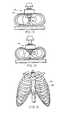
- the compressor pad 19, as best illustrated in Figure 6, is positioned anterior to the patient's heart 45 in contact with the lower portion of the patient's sternum 46.
- An external electrode 48 is disposed on a face 49 of the compressor pad 19 for compression between the compressor pad 19 and the patient's sternum 46.
- the body 50 of the compressor pad 19 is preferably moulded from a flexible closed cell integral skin polyurethane foam.
- the body 50 is mounted on a planar support 51.
- the face 49 of the compressor pad 19 preferably extends over an area greater than that of conventional external com- presser pads and an area much greater than the manual "heel of hand” contact area normally available when the manual CPR technique is applied.
- the area of face 49 is preferably approximately eight times larger than the normal manual "heel of hand” contact ared.
- the external electrede 48 covers a relatively large area of the face 49 and is preferably ten square inches or more in area. Electrode 48 is isolated electrically from all metal parts of the CPR assembly except that it is electrically connected to a terminal 54 disposed at the top of the assembly by multiple internal flexible leads shown in phantom at 55 in Figure 2.
- the electrode 48 is preferably flexible to conform to the shape of the patient's chest and sternum and a metal mesh screen electrode vulcanised to the face 49 of the compressor pad 19 is preferred. Gold plated brass mesh screens and silver mesh screens have both been found suitable. However, a suitable conductive elastomer may also be employed for the body 50 of compressor pad 19, or for at least the face 49 of the body 50 to act as the electrode 48.
- the planar support 51 for the body 50 of compressor pad 19 includes a hinge or pin-type connection 58 so that the compressor pad 19 may be pinned to the piston 18 of the CPR unit 10.
- This hinged connection is preferable since the patient's sternum 46 is not always horizontally oriented when the patient is in the supine position, as illustrated in Figure 6.
- This hinged, or pinned, connection allows the compressor pad 19 to more closely follow or conform to the patient's chest.
- the base 49 of the body 50 of the compressor pad 19 is preferably moulded to conform to the outline of the human chest.
- the body 50 of flexible foam then further acts to accommodate minor variations in the size of each patient's chest
- a first internal electrode 60 is provided, the first internal electrode 60 being positioned posterior to the patient's heart 45.
- the first internal electrode 60 is disposed in the patient's oesophagus. Means for positioning the first internal electrode 60 is illustrated in further detail in Figures 7, 8, 9, 10 and 11.
- means for positioning the first internal electrode 60 comprises a closed, flexible plastic tube 65, which is insertable in the patient's oesophagus.
- the tube 65 is preferably made of a flexible polymer to facilitate insertion in the patient's oesophagus.
- a flexible first internal electrode in the form of a plurality of metalized strips 66 are disposed on the distal end 67 of the tube 65.
- the electrode strips 66 may be four to ten centimetres in length.
- the electrode strips 66 may be centred directly behind the patient's heart by connecting an ECG monitor to a lead 69 and then varying the position of the tube 65 in the patient's oesophagus until the point at which an ECG signal of maximum amplitude is obtained.
- the electrode strips 66 should be centred directly posterior to the patient's heart and defibrillation may be carried out. It is to noted that if the tube 65 is sufficiently resilient, the tube may be open at both ends such that the tube 65 acts as a gastric drain.
- an expandable or inflatable cuff 70 is preferably provided on oesophageal tube 65 for sealing the patient's oesophagus about the tube 65.
- the oesophageal cuff 70 is preferred since, during prolonged, external cardiac compression, the possibility of food and gastric juices escaping the oesophagus and being aspirated by the patient is significant.
- Such an inflatable oesophageal cuff 70 may be employed when the tube 65 is hollow and used as a gastric drain.
- the inflatable cuff is illustrated as being disposed adjacent the distal end 67 of the oesophageal tube 65, it is to be understood that the inflatable cuff 70 may be disposed anywhere along the length of the oesophageal tube 65 to effectively seal the oesophagus.
- a first internal electrode 60 comprising a plurability of flexible metallic strips 72 disposed on the exterior of an inflatable cuff 73.
- the electrode strips 72 are formed of a flexible, highly conductive metal such as silver, gold or copper, and since such strips are not stretchable in response to cuff inflating forces, collapse of the cuff involves an overlapping or interleaving of the conductive strips 72 and the non-conductive resilient wall portions of the cuff 73, as best illustrated in Figure 10.
- the resilient and stretchable synthetic rubber or plastics material of the cuff or the oesophageal tube may be impregnated with metallic particles or fibres or the like, thereby providing a wall construction that is both stretchable and conductive.
- a conductive polymer, plastics or other elastomer may be used as an electrode.
- second and third internal electrodes 75 and 76 are also provided to facilitate centring of the first internal electrode 60.
- Such orienting and monitoring electrodes 75 and 76 may take the form of small patches or circumferential strips which are positioned on the top and bottom of the outer surface of the cuff 73 and which are insulated from each other and from the electrode strips 72.
- Leads 77 and 78 extend through the tube 65 to connect the electrodes 75 and 76 to a conventional electrocardiograph or ECG monitor.
- a lead 69 connects the first electrode strips 72 to monitoning end/or defibrillation circuits.
- the oesophageal-pharyngeal airway of Figure 11 comprises an oesophageal tube 65 which extends through an air tube 80 in a concentric relationship.
- the oesophageal tube 65 is hollow and is connected to a collector 81 for draining food and gastric juices from the patient's stomach.
- the collector 81 may be a vomit bag, or a syringe or other device, for introducing fluids to the stomach and flushing or otherwise treating the stomach.
- the air tube 80 is connected to the integral pnuema- tically operated ventilation and cardiac compression apparatus illustrated in Figure 1.
- the tubes 65 and 80 are formed of a relatively soft, flexible, nonirritating plastics material such as polyvinyl chloride.
- the oesophageal-pharyngeal airway illustrated in Figure 11 is provided with an oesophageal cuff 85 for sealing the patient's oesophagus about the oesophageal tube 65 and an oral cuff, or bulbous shape, 87 for sealing the patient's soft palate and nasal passages.
- a movable oral flange 89 covers the patient's mouth and is secured thereto by straps 90 or other suitable means.
- One or both of the cuffs may be inflated and deflated through passages or small tubes 91 and 92.
- the passages 91 and 92 may be connected to suitable inflation means such as a syringe or the like, or alternatively, the cuffs may be inflated and partially deflated with each respiratory cycle.
- suitable inflation means such as a syringe or the like
- the cuffs may be inflated and partially deflated with each respiratory cycle.
- the repetitiously inflatable and deflatable cuffs are supplied by air from the main air tube or ventilator through ports placing each cuff in communication with the air tube.
- Such ports are dimensioned so that air supply to the patient first enters and inflates the cuff and,when flow is then reversed, air is first extracted from the cuff.
- the oesophageal tube 65 preferably carries a plurality of electrodes generally indicated by the numeral 83.
- the electrodes disposed at 83 comprise a plurality of longitudinally expending electrode strips 95 which act as the first internal electrode 60 illustrated in Figure 6.
- this first internal electrode 95 is disposed distally of the oesophageal cuff 85 on a portion of the oesophageal tube 65 since this allows placement of the oesophageal cuff 85 anywhere in the patient's oesophagus and, in fact, allows the placement of the cuff 85 at a higher spot in the oesophagus where trauma to the patient due to inflation of the oesophageal cuff will be minimised.
- the electrode strips 95 may comprise flexible metal strips or a conductive elastomer.
- the first internal electrode 60 is accompanied by second and third internal electrodes 96 and 97 disposed on the oesophageal tube 65 above and below the first internal electrode 60, respectively.
- the second and third internal electrodes 96 and 97 are employed to monitor the electrical activity of the heart and to centre the first internal electrode 60 with respect to the heart as previously discussed.
- the first internal electrode 60 may be centered by any one of a variety of techniques, including amplitude monitoring of the electrical activity of the heart as perceived by the first internal electrode 60 and/or by simply gauging the oesophageal tube length before it is inserted relative to the patient's sternum, in particular, the patient's zyphoid process which is disposed at the lower end of the patient's sternum. In this case, the oesophageal tube 65 would simply be marked at the appropriate point and inserted to ensure an adequate approximate positioning relative to the heart.
- the electrodes 96 and 97 are each connected via lines 77 and 78 to an ECG heart monitor.
- the first internal electrode 95 may also be connected to an ECG heart monitor, but is alternatively connectable to a defibrillator for passing a defibrillating electric current through the patient's heart.
- the external electrode carried on compressor pad 19 is also connected to the defibrillator 100 and/or an ECG monitor 101.
- the one external electrode and the three internal electrodes would provide four different positions for monitoring the electrical activity of the heart.
- suitable switching means 102 and 103 will be used to isolate the monitor from the defibrillator during defibrillator operation.
- the apparatus further includes means for synchronising the defibrillator and the compressor, preferably comprising a pressure sensitive switch 105 for sensing pneumatic pressure within the power cylinder 17 of the CPR unit 10.
- the pressure switch 105 acts to disable the defibrillator unit except when pressure within the power cylinder 17 reaches a predetermined value.
- the pressure switch is set to allow the application of a defibrillating shock only during, or close to, the period of maximum compression in the compressor cycle.
- the pressure switch is adjustable, the time in the compression cycle during which the defibrillating shock may be applied may be varied. Adjustability of the pressure switch is also important where it is desirable to apply the defibrillating shock only at the point of maximum compression since the maximum compression pressure will vary with different patients.
- Standard defibrillator and monitor circuits may be employed in the apparatus described although a defibrillator of much less power than standard defibrillator circuits may be employed.
- Standard defibrillating circuits include hand-held electrodes or paddles having defibrillating control switches disposed thereon. These standard, commercially available, defibrillating circuits could be modified for use with the apparatus described by wiring these standard paddle switches or their equivalents in series with the pressure actuated switch 105 such that manual actuation of the defibrillator is effective only during the time period when the pressure in the power cylinder 17 closes the switch 105, indicating that the compressor is i.n a systolic portion of the compressor cycle.
- FIGURES 1 and 6 to employ the described apparatus with a patient requiring cardiac compression for blood perfusion and lung ventilation or blood oxygenisation, the patient is placed in the illustrated position (FIGURE 6) with his back on platform 12.
- the cardiac compressor is then adjusted so that the compressor pad 19 is immediately over the lower portion of the patient's sternum 46.
- the arm 14 of the cardiac compressor is vertically adjusted on the columnar support 13 so that the pad 19 contacts the breast bone or sternum when the pad and plunger are in the raised position.
- a gas supply hose from a conventional source of pressurised oxygen is then connected to the unit at 30.
- the cardiac compressor equipment is actuated and adjusted to create the desired chest deflection by adjustment of the knob 24 and monitoring of the pressure gauge 25.
- the oesophageal tube 65 carrying the first internal electrode 60 is inserted in the patient's oesophagus.
- the first internal electrode 60 may be centered directly below or posterior of the patient's heart 45 by amplitude monitoring of the electrical activity of the patient's heart as perceived by the first internal electrodes 60 or by monitoring of the second and third internal electrodes 75 and 76 or by simply gauging the length of the tube 65 according to the distance between the patient's neck and zyphoid process.
- an oesophageal cuff may be inflated along with an oral cuff if an air tube is also inserted.
- a simple face mask with or without an oral airway may be employed.
- the ventilation subassembly 26 may be actuated and adjusted with the adjustment knob 24' while monitoring the pressure gauge 25'.
- a collector may also be connected to the oesophageal tube 65 if so desired.
- the internal electrodes in particular provide extremely high, strong, very clean signals for monitoring the electrical activity of the heart. Although these signals are slightly distorted by the activity of the CPR unit, these signals are strong and clear enough to detect gross arrhythmias such as ventricular fibrillation. Thus, effective monitoring of the electrical activity of the heart is achieved during normal operation of the supportive CPR unit.
- the combination of the first internal electrode and the external electrode on the compressor pad 19 provides a short, direct electrical path through the heart, dramatically reducing the amount of power required to defibrillate the heart.
- FIGURES 12, 13, and 14 it is illustrated that this electrical path is further shortened by use of apparatus according to the present invention.
- FIGURE 13 illustrating the compressor pad 19 in the diastole or fully retracted position, the lines 110 represent the electrical conductive path which would exist if current for defibrillation were to be passed at this stage.
- FIGURE 14 illustrates that by synchronizing defibrillation shock with the systole portion of the compression cycle, the internal electrode 60 is captured between the heart 45 and the vertebral column 112 to establish intimate contact between the inner electrode and the inner wall of the oesophagus and to further substantially decrease the current path between the inner electrode 60 and the outer electrode 48 as illustrated by the lines 111.
- the prosent invention provides an improved electrical path for administration of electrical defibrillation shocks to the heart.
- a gress archytimia such as ventricular fibrillation
- the operator may apply definitive therapy such as a defibrillation shock to the patient's heart by simply actuating a manual push bution on the defibrillator, the manual push bution conresponding to the paddle buttens normally provided on contional defibrillator prddles.
- These paddle buttons weuld simply be depressed until the siries wried sychising pressure switch 105 systolic portion of the cycle has been reached and triggering the defibrillation hock.
- the be terporatily disconnected from the defibrillating electrodes during defibrillation This can be accomplished by making the switches 102 and 103 automatically actuable by the manually actuable defibrillator push button.
- the monitor may be returned to operation and as the residual effects of the defibrillation shocks subside, an accurate picture of the electrical activity of the patient's heart should again appear.
- the switch 105 will generally be adjustable such that the operator may precisely time the defibrillation shocks to the point of maximum co-pression of the CPR unit.
- the operation of the CPR unit need not vary, since it is now being used in conjunction with an electric defibrillator, there are engoing studies en the state of the art of external cardiac compression, and it may be that are optimal fiequeines and dwell times than these employed prenently may be achicved in the future. In particular, it is pessible that the relationship of ventition to pression will be optimised a hit differently than that presently used. However, there will always be a finite period of systole in which defibrillation could be accomplished according to the present invention.
- defibrillator operated according to the present invention, it is possible to build defibrillators opercating with an expected power requirment of 20 to 30 joules, and prebably no more than 50 joules.
- a defibrillator of very small, compact, lewer, power may be designed which could be powered by rechargable nickel cadium batterjes, or the like .
- the advantages in the portability and the reduction in cost of such a defibrillator should be self cvident.
- the apparatus of the present invention provides a unique arrangement for applying both supportive and definitive therapy to a patient in cardiac arrest. More specifically, the described apparatus provides for simultaneous external cardiac compression and ventilation of the parient while the elecirical activity of the patient is coniinensly monitored for gross arrhythmies and defibrillating shocks are periodically applied directly through the heart's myocardium.
- the apparatus provides for simultaneous external cardiac compression and ventilation of the parient while the elecirical activity of the patient is coniinensly monitored for gross arrhythmies and defibrillating shocks are periodically applied directly through the heart's myocardium.
- the apparatus of the present invention provides a unique arrangement for applying both supportive and definitive therapy to a patient in cardiac arrest.
Landscapes
- Health & Medical Sciences (AREA)
- Cardiology (AREA)
- Heart & Thoracic Surgery (AREA)
- Animal Behavior & Ethology (AREA)
- Veterinary Medicine (AREA)
- Public Health (AREA)
- General Health & Medical Sciences (AREA)
- Life Sciences & Earth Sciences (AREA)
- Pulmonology (AREA)
- Emergency Medicine (AREA)
- Biomedical Technology (AREA)
- Engineering & Computer Science (AREA)
- Rehabilitation Therapy (AREA)
- Pain & Pain Management (AREA)
- Radiology & Medical Imaging (AREA)
- Physical Education & Sports Medicine (AREA)
- Nuclear Medicine, Radiotherapy & Molecular Imaging (AREA)
- Epidemiology (AREA)
- Hematology (AREA)
- Anesthesiology (AREA)
- Critical Care (AREA)
- Electrotherapy Devices (AREA)
- Percussion Or Vibration Massage (AREA)
- Soil Working Implements (AREA)
- Processing Of Meat And Fish (AREA)
- Surgical Instruments (AREA)
Priority Applications (1)
| Application Number | Priority Date | Filing Date | Title |
|---|---|---|---|
| AT79302275T ATE2930T1 (de) | 1978-10-19 | 1979-10-19 | Pneumokardialer wiederbelebungsapparat. |
Applications Claiming Priority (2)
| Application Number | Priority Date | Filing Date | Title |
|---|---|---|---|
| US05/952,656 US4198963A (en) | 1978-10-19 | 1978-10-19 | Cardiopulmonary resuscitator, defibrillator and monitor |
| US952656 | 1978-10-19 |
Publications (2)
| Publication Number | Publication Date |
|---|---|
| EP0010908A1 true EP0010908A1 (fr) | 1980-05-14 |
| EP0010908B1 EP0010908B1 (fr) | 1983-04-06 |
Family
ID=25493109
Family Applications (1)
| Application Number | Title | Priority Date | Filing Date |
|---|---|---|---|
| EP79302275A Expired EP0010908B1 (fr) | 1978-10-19 | 1979-10-19 | Appareil de réanimation cardiopulmonaire |
Country Status (7)
| Country | Link |
|---|---|
| US (1) | US4198963A (fr) |
| EP (1) | EP0010908B1 (fr) |
| JP (1) | JPS5554965A (fr) |
| AT (1) | ATE2930T1 (fr) |
| CA (1) | CA1133586A (fr) |
| DE (1) | DE2965148D1 (fr) |
| ES (1) | ES485141A1 (fr) |
Cited By (6)
| Publication number | Priority date | Publication date | Assignee | Title |
|---|---|---|---|---|
| EP0104287A1 (fr) * | 1978-01-30 | 1984-04-04 | Eugene Nelson Scarberry | Appareil médical d'urgence |
| EP0112082A3 (fr) * | 1982-12-03 | 1985-05-15 | Canadian Patents and Development Limited Société Canadienne des Brevets et d'Exploitation Limitée | Méthode et dispositif pour l'augmentation de la contractilité cardiaque |
| WO1988003822A1 (fr) * | 1986-11-20 | 1988-06-02 | C.B. Bioelettronica S.R.L. | Appareil pour stimulation cardiaque transoesophagienne, mis en oeuvre avec un seuil d'energie reduit au minimum, et methode de stimulation s'y rapportant |
| GB2220356A (en) * | 1988-07-05 | 1990-01-10 | Brunswick Mfg Co Ltd | Defibrillating the heart using internal esophageal electrode and external chest electrode |
| WO1994026229A1 (fr) * | 1993-05-03 | 1994-11-24 | Markku Moilanen | Appareil de reanimation |
| WO1995008316A1 (fr) * | 1993-09-24 | 1995-03-30 | Willy Vistung | Appareil de massage cardiaque mobile |
Families Citing this family (153)
| Publication number | Priority date | Publication date | Assignee | Title |
|---|---|---|---|---|
| US4522205A (en) * | 1980-09-03 | 1985-06-11 | The University Court Of The University Of Edinburgh | Therapeutic device and method of inducing thrombosis in a blood vessel |
| US4630611A (en) * | 1981-02-02 | 1986-12-23 | Medtronic, Inc. | Orthogonally-sensing lead |
| US4424806A (en) | 1981-03-12 | 1984-01-10 | Physio-Control Corporation | Automated ventilation, CPR, and circulatory assistance apparatus |
| US4750494A (en) * | 1981-05-12 | 1988-06-14 | Medtronic, Inc. | Automatic implantable fibrillation preventer |
| US4706688A (en) * | 1981-05-18 | 1987-11-17 | Don Michael T Anthony | Non-invasive cardiac device |
| DE3242814A1 (de) * | 1982-11-19 | 1984-05-24 | Siemens AG, 1000 Berlin und 8000 München | Verfahren und respirator zur beatmung eines patienten im herzrhytmus und zur unterstuetzung der blutzirkulation |
| US4519403A (en) * | 1983-04-29 | 1985-05-28 | Medtronic, Inc. | Balloon lead and inflator |
| JPS6052828U (ja) * | 1983-09-20 | 1985-04-13 | 林原 健 | ゼンソク治療用振動装置 |
| US4574807A (en) * | 1984-03-02 | 1986-03-11 | Carl Hewson | Method and apparatus for pacing the heart employing external and internal electrodes |
| FR2579469B2 (fr) * | 1984-03-27 | 1989-03-24 | Atesys | Electrode pour les appareils de traitement des troubles du rythme cardiaque |
| FR2561929B1 (fr) * | 1984-03-27 | 1989-02-03 | Atesys | Appareillage automatique implante pour la defibrillation ventriculaire |
| US4649924A (en) * | 1984-08-14 | 1987-03-17 | Consiglio Nazionale Delle Ricerche | Method for the detection of intracardiac electrical potential fields |
| GB8431500D0 (en) * | 1984-12-13 | 1985-01-23 | Antec Systems | Measurement of thoracic impedances |
| JPH064097B2 (ja) * | 1985-03-20 | 1994-01-19 | ブランズウィック・バイオメディカル・テクノロジーズ・インコーポレーテッド | 心臓整調装置 |
| US4658835A (en) * | 1985-07-25 | 1987-04-21 | Cordis Corporation | Neural stimulating lead with fixation canopy formation |
| US4683890A (en) * | 1985-12-23 | 1987-08-04 | Brunswick Manufacturing Co., Inc. | Method and apparatus for controlled breathing employing internal and external electrodes |
| US4861337A (en) * | 1988-03-02 | 1989-08-29 | Sherwood Medical Company | Collapsible urethral catheter |
| US4960133A (en) * | 1988-11-21 | 1990-10-02 | Brunswick Manufacturing Co., Inc. | Esophageal electrode |
| JPH03218763A (ja) * | 1988-12-12 | 1991-09-26 | Shinatsushin Kurinitsuku:Kk | マッサージ器 |
| US5191885A (en) * | 1989-02-06 | 1993-03-09 | Arczo Medical Electronics, Inc. | Method of terminating an arrhythmia |
| US5343860A (en) * | 1989-02-06 | 1994-09-06 | Arzco Medical Systems, Inc. | Esophageal recording/pacing catheter with thermistor and cardiac imaging transceiver |
| US5056532A (en) * | 1989-07-25 | 1991-10-15 | Medtronic, Inc. | Esophageal pacing lead |
| US5056514A (en) * | 1989-10-30 | 1991-10-15 | Dupont Frank | Endotracheal stethoscope |
| US5178149A (en) * | 1989-11-06 | 1993-01-12 | Michael Imburgia | Transesophageal probe having simultaneous pacing and echocardiographic capability, and method of diagnosing heart disease using same |
| US5024228A (en) * | 1989-11-29 | 1991-06-18 | Goldstone Andrew C | Electrode endotracheal tube |
| US5125406A (en) * | 1989-11-29 | 1992-06-30 | Eet Limited Partnership (Del) | Electrode endotracheal tube |
| US5179952A (en) * | 1990-08-13 | 1993-01-19 | Arzco Medical Electronics Inc. | Electrocardial stimulator probe |
| US5645522A (en) * | 1991-04-17 | 1997-07-08 | The Regents Of The University Of California | Devices and methods for controlled external chest compression |
| AU651189B2 (en) * | 1991-04-17 | 1994-07-14 | Regents Of The University Of California, The | Improved devices and methods for external chest compression |
| US6086581A (en) * | 1992-09-29 | 2000-07-11 | Ep Technologies, Inc. | Large surface cardiac ablation catheter that assumes a low profile during introduction into the heart |
| US5327887A (en) * | 1993-01-25 | 1994-07-12 | Ludwik Nowakowski | Cardiopulmonary resuscitation device |
| US5626618A (en) * | 1993-09-24 | 1997-05-06 | The Ohio State University | Mechanical adjunct to cardiopulmonary resuscitation (CPR), and an electrical adjunct to defibrillation countershock, cardiac pacing, and cardiac monitoring |
| US5474533A (en) * | 1994-04-11 | 1995-12-12 | The Ohio State University | Intrathoracic mechanical, electrical and temperature adjunct to cardiopulmonary cerebral resuscitation, shock, head injury, hypothermia and hyperthermia |
| US5716386A (en) * | 1994-06-27 | 1998-02-10 | The Ohio State University | Non-invasive aortic impingement and core and cerebral temperature manipulation |
| US5743864A (en) * | 1995-06-29 | 1998-04-28 | Michigan Instruments, Inc. | Method and apparatus for performing cardio-pulmonary resuscitation with active reshaping of chest |
| US5655518A (en) * | 1995-08-22 | 1997-08-12 | Burden; Brant S. | Coupling device for a stethoscope and an endotracheal tube |
| US5738637A (en) * | 1995-12-15 | 1998-04-14 | Deca-Medics, Inc. | Chest compression apparatus for cardiac arrest |
| US20040199209A1 (en) * | 2003-04-07 | 2004-10-07 | Hill Michael R.S. | Method and system for delivery of vasoactive drugs to the heart prior to and during a medical procedure |
| US8036741B2 (en) * | 1996-04-30 | 2011-10-11 | Medtronic, Inc. | Method and system for nerve stimulation and cardiac sensing prior to and during a medical procedure |
| US6449507B1 (en) * | 1996-04-30 | 2002-09-10 | Medtronic, Inc. | Method and system for nerve stimulation prior to and during a medical procedure |
| US6904318B2 (en) * | 2000-09-26 | 2005-06-07 | Medtronic, Inc. | Method and system for monitoring and controlling systemic and pulmonary circulation during a medical procedure |
| US6628987B1 (en) * | 2000-09-26 | 2003-09-30 | Medtronic, Inc. | Method and system for sensing cardiac contractions during vagal stimulation-induced cardiopalegia |
| US7225019B2 (en) | 1996-04-30 | 2007-05-29 | Medtronic, Inc. | Method and system for nerve stimulation and cardiac sensing prior to and during a medical procedure |
| US7269457B2 (en) * | 1996-04-30 | 2007-09-11 | Medtronic, Inc. | Method and system for vagal nerve stimulation with multi-site cardiac pacing |
| US6193680B1 (en) | 1996-06-18 | 2001-02-27 | William R. Parsons | Intrathoracic cardiac compression |
| SE9603841D0 (sv) * | 1996-10-18 | 1996-10-18 | Pacesetter Ab | A tissue stimulating apparatus |
| AU8472798A (en) | 1997-06-27 | 1999-01-19 | Michigan Instruments, Inc. | Non-invasive aortic impingement |
| US6479523B1 (en) * | 1997-08-26 | 2002-11-12 | Emory University | Pharmacologic drug combination in vagal-induced asystole |
| US6736790B2 (en) * | 1998-02-25 | 2004-05-18 | Denise R. Barbut | Method and system for selective or isolated integrate cerebral perfusion and cooling |
| US6740082B2 (en) * | 1998-12-29 | 2004-05-25 | John H. Shadduck | Surgical instruments for treating gastro-esophageal reflux |
| US6213960B1 (en) * | 1998-06-19 | 2001-04-10 | Revivant Corporation | Chest compression device with electro-stimulation |
| US6154668A (en) * | 1998-08-06 | 2000-11-28 | Medtronics Inc. | Ambulatory recorder having a real time and non-real time processors |
| US6128520A (en) * | 1998-08-06 | 2000-10-03 | Medtronic, Inc. | Ambulatory recorder having volatile and non-volatile memories |
| US6200264B1 (en) | 1998-08-06 | 2001-03-13 | Medtronic Inc. | Ambulatory recorder having wireless data transfer with a multi-plane lens |
| US6119029A (en) * | 1998-08-06 | 2000-09-12 | Medtronic, Inc. | Ambulatory recorder having splash resistant sensor ports |
| US6115622A (en) * | 1998-08-06 | 2000-09-05 | Medtronic, Inc. | Ambulatory recorder having enhanced sampling technique |
| US6014578A (en) * | 1998-08-06 | 2000-01-11 | Meotronic, Inc. | Ambulatory recorder having method of configuring size of data subject to loss in volatile memory |
| US6077223A (en) * | 1998-08-06 | 2000-06-20 | Medtronic, Inc. | Ambulatory recorder having control screen to present dual interface for dual users |
| US6141574A (en) * | 1998-08-06 | 2000-10-31 | Medtronic, Inc. | Ambulatory recorder having sliding period switches |
| US6142938A (en) * | 1998-08-06 | 2000-11-07 | Medtronic Inc. | Ambulatory data recorder having ergonomically shaped housing |
| USRE38533E1 (en) * | 1998-09-11 | 2004-06-15 | Life Corporation | Portable emergency oxygen and automatic external defibrillator (AED) therapy system |
| US6327497B1 (en) * | 1998-09-11 | 2001-12-04 | Life Corporation | Portable emergency oxygen and automatic external defibrillator (AED) therapy system |
| US6245013B1 (en) | 1998-12-14 | 2001-06-12 | Medtronic, Inc. | Ambulatory recorder having synchronized communication between two processors |
| US6171267B1 (en) | 1999-01-07 | 2001-01-09 | Michigan Instruments, Inc. | High impulse cardiopulmonary resuscitator |
| CA2376903A1 (fr) | 1999-06-25 | 2001-01-04 | Emory University | Dispositifs et methodes de stimulation du nerf vague |
| NO311746B1 (no) * | 1999-08-27 | 2002-01-21 | Laerdal Medical As | System for å redusere signalforstyrrelser i EKG forårsaket av hjerte-lunge-redning |
| US6374827B1 (en) * | 1999-10-05 | 2002-04-23 | O-Two Systems International Inc. | Tracheo-esophageal tube and ventilator for pneumatic cardiopulmonary resuscitation |
| US6382207B1 (en) * | 1999-12-10 | 2002-05-07 | Hackensack University Medical Center | Device and method for preventing ignition of an endotracheal tube during laser surgery |
| TW407053B (en) * | 2000-01-21 | 2000-10-01 | Jang Ting Tsai | Automatic inflation cardiopulmonary resuscitation apparatus with both electric and manual operation modes |
| US20060064131A1 (en) * | 2000-02-04 | 2006-03-23 | Freeman Gary A | User interface for defibrillator for use by persons with limited training and experience |
| US20050131465A1 (en) | 2000-02-04 | 2005-06-16 | Freeman Gary A. | Integrated resuscitation |
| EP1251908B1 (fr) * | 2000-02-04 | 2017-04-05 | Zoll Medical Corporation | Reanimation integree |
| US6487446B1 (en) * | 2000-09-26 | 2002-11-26 | Medtronic, Inc. | Method and system for spinal cord stimulation prior to and during a medical procedure |
| US6553257B2 (en) * | 2001-03-13 | 2003-04-22 | Koninklijke Philips Electronics N.V. | Interactive method of performing cardipulmonary resuscitation with minimal delay to defibrillation shocks |
| US7569021B2 (en) * | 2002-03-21 | 2009-08-04 | Jolife Ab | Rigid support structure on two legs for CPR |
| US6827695B2 (en) | 2002-10-25 | 2004-12-07 | Revivant Corporation | Method of determining depth of compressions during cardio-pulmonary resuscitation |
| US8036742B2 (en) * | 2003-01-31 | 2011-10-11 | Physio-Control, Inc. | Apparatus and methods for fibrillation and defibrillation |
| US7613515B2 (en) * | 2003-02-03 | 2009-11-03 | Enteromedics Inc. | High frequency vagal blockage therapy |
| US7844338B2 (en) | 2003-02-03 | 2010-11-30 | Enteromedics Inc. | High frequency obesity treatment |
| US20040172084A1 (en) * | 2003-02-03 | 2004-09-02 | Knudson Mark B. | Method and apparatus for treatment of gastro-esophageal reflux disease (GERD) |
| US7444183B2 (en) * | 2003-02-03 | 2008-10-28 | Enteromedics, Inc. | Intraluminal electrode apparatus and method |
| US20040162510A1 (en) * | 2003-02-14 | 2004-08-19 | Medtronic Physio-Control Corp | Integrated external chest compression and defibrillation devices and methods of operation |
| US7308304B2 (en) | 2003-02-14 | 2007-12-11 | Medtronic Physio-Control Corp. | Cooperating defibrillators and external chest compression devices |
| US20050038475A1 (en) * | 2003-02-18 | 2005-02-17 | Medtronic Physio-Control Corp. | Defibrillators learning of other concurrent therapy |
| EP3064242A1 (fr) | 2003-04-28 | 2016-09-07 | Advanced Circulatory Systems Inc. | Ventilateur et procédés de traitement de traumatisme crânien et d'hypotension |
| US7226427B2 (en) * | 2003-05-12 | 2007-06-05 | Jolife Ab | Systems and procedures for treating cardiac arrest |
| US20050085799A1 (en) * | 2003-06-12 | 2005-04-21 | Oded Luria | Emergency medical kit, respiratory pump, and face mask particularly useful therein |
| US7190999B2 (en) * | 2003-06-27 | 2007-03-13 | Zoll Medical Corporation | Cardio-pulmonary resuscitation device with feedback from measurement of pulse and/or blood oxygenation |
| US20050148909A1 (en) * | 2003-07-15 | 2005-07-07 | Weil Max H. | Light weight chest compressor |
| JP2012091021A (ja) | 2003-11-06 | 2012-05-17 | Zoll Medical Corp | 胸部圧迫適用中の生理学的信号を解析する装置 |
| US20050101889A1 (en) | 2003-11-06 | 2005-05-12 | Freeman Gary A. | Using chest velocity to process physiological signals to remove chest compression artifacts |
| WO2005112749A1 (fr) | 2004-05-12 | 2005-12-01 | Zoll Medical Corporation | Procede de recommandation pour rythme ecg |
| US7565194B2 (en) * | 2004-05-12 | 2009-07-21 | Zoll Medical Corporation | ECG rhythm advisory method |
| US7645247B2 (en) * | 2004-10-25 | 2010-01-12 | Norman A. Paradis | Non-invasive device for synchronizing chest compression and ventilation parameters to residual myocardial activity during cardiopulmonary resuscitation |
| US9259543B2 (en) | 2004-10-25 | 2016-02-16 | Zoll Medical Corporation | Non-invasive device for synchronizing chest compression and ventilation parameters to residual myocardial activity during cardiopulmonary resuscitation |
| US7219667B2 (en) * | 2004-12-17 | 2007-05-22 | Tien-Tsai Chang | Hand press type rapid positioning first-aid device with cardiopulmonary resuscitation |
| US7822486B2 (en) * | 2005-08-17 | 2010-10-26 | Enteromedics Inc. | Custom sized neural electrodes |
| US7672727B2 (en) | 2005-08-17 | 2010-03-02 | Enteromedics Inc. | Neural electrode treatment |
| US7650181B2 (en) * | 2005-09-14 | 2010-01-19 | Zoll Medical Corporation | Synchronization of repetitive therapeutic interventions |
| US20070169779A1 (en) * | 2006-01-24 | 2007-07-26 | Freeman Gary A | Reperfusion protection in resuscitation |
| US10071218B2 (en) | 2006-01-24 | 2018-09-11 | Zoll Medical Corporation | Reperfusion protection in resuscitation |
| US9421389B2 (en) | 2006-02-15 | 2016-08-23 | Koninklijke Philips N.V. | CPR assistance and effectiveness display |
| US8105249B2 (en) | 2006-02-16 | 2012-01-31 | Zoll Medical Corporation | Synchronizing chest compression and ventilation in cardiac resuscitation |
| US9352111B2 (en) | 2007-04-19 | 2016-05-31 | Advanced Circulatory Systems, Inc. | Systems and methods to increase survival with favorable neurological function after cardiac arrest |
| US8151790B2 (en) * | 2007-04-19 | 2012-04-10 | Advanced Circulatory Systems, Inc. | Volume exchanger valve system and method to increase circulation during CPR |
| EP2170458A1 (fr) * | 2007-06-13 | 2010-04-07 | E- Pacing, Inc. | Dispositifs implantables et procédés destinés à stimuler des tissus cardiaques ou d'autres tissus |
| US8478401B2 (en) * | 2007-11-01 | 2013-07-02 | Zoll Medical Corporation | Synchronization of defibrillation and chest compressions |
| WO2010045222A1 (fr) * | 2008-10-13 | 2010-04-22 | E-Pacing, Inc. | Dispositifs et procédés de stimulation électrique du diaphragme et des nerfs |
| US8386010B2 (en) * | 2008-10-23 | 2013-02-26 | Covidien Lp | Surgical tissue monitoring system |
| US12064391B2 (en) | 2010-02-12 | 2024-08-20 | Zoll Medical Corporation | Defibrillator display including CPR depth information |
| US8880166B2 (en) | 2010-02-12 | 2014-11-04 | Zoll Medical Corporation | Defibrillator display |
| JP2013519446A (ja) * | 2010-02-12 | 2013-05-30 | ゾール メディカル コーポレイション | 除細動器の充電 |
| US12016820B2 (en) | 2010-02-12 | 2024-06-25 | Zoll Medical Corporation | Enhanced guided active compression decompression cardiopulmonary resuscitation systems and methods |
| US9724266B2 (en) | 2010-02-12 | 2017-08-08 | Zoll Medical Corporation | Enhanced guided active compression decompression cardiopulmonary resuscitation systems and methods |
| US8725253B2 (en) | 2010-02-12 | 2014-05-13 | Zoll Medical Corporation | Defibrillator display including CPR depth information |
| US20110218467A1 (en) * | 2010-03-03 | 2011-09-08 | Chin-Fu Hsu | Portable cardiopulmonary resuscitator for implementing cardiopulmonary resuscitation |
| US8423134B2 (en) | 2010-04-29 | 2013-04-16 | Medtronic, Inc. | Therapy using perturbation and effect of physiological systems |
| US8620425B2 (en) | 2010-04-29 | 2013-12-31 | Medtronic, Inc. | Nerve signal differentiation in cardiac therapy |
| US8639327B2 (en) | 2010-04-29 | 2014-01-28 | Medtronic, Inc. | Nerve signal differentiation in cardiac therapy |
| US8825164B2 (en) | 2010-06-11 | 2014-09-02 | Enteromedics Inc. | Neural modulation devices and methods |
| US9198826B2 (en) | 2010-07-13 | 2015-12-01 | Physio-Control, Inc. | CPR chest compression machine stopping to detect patient recovery |
| US20120029321A1 (en) * | 2010-07-27 | 2012-02-02 | Advanced Circulatory Systems, Inc. | Airway adjunct resuscitation systems and methods |
| US8706223B2 (en) | 2011-01-19 | 2014-04-22 | Medtronic, Inc. | Preventative vagal stimulation |
| US8781583B2 (en) | 2011-01-19 | 2014-07-15 | Medtronic, Inc. | Vagal stimulation |
| US8781582B2 (en) | 2011-01-19 | 2014-07-15 | Medtronic, Inc. | Vagal stimulation |
| US8718763B2 (en) | 2011-01-19 | 2014-05-06 | Medtronic, Inc. | Vagal stimulation |
| US8725259B2 (en) | 2011-01-19 | 2014-05-13 | Medtronic, Inc. | Vagal stimulation |
| JP2015500733A (ja) | 2011-12-19 | 2015-01-08 | レスキューシステムズ インコーポレイテッドResqsystems,Inc. | 治療のための胸腔内圧調節システムおよび方法 |
| EP2698141A1 (fr) * | 2012-08-14 | 2014-02-19 | Schiller AG | Appareil d'assistance à la réanimation cardio-pulmonaire |
| US9713568B2 (en) | 2012-12-21 | 2017-07-25 | Physio-Control, Inc. | Mechanical CPR device with automatic suction cup attachment |
| US9811634B2 (en) | 2013-04-25 | 2017-11-07 | Zoll Medical Corporation | Systems and methods to predict the chances of neurologically intact survival while performing CPR |
| US20140323928A1 (en) | 2013-04-30 | 2014-10-30 | Zoll Medical Corporation | Compression Depth Monitor with Variable Release Velocity Feedback |
| US20140358047A1 (en) | 2013-05-30 | 2014-12-04 | ResQSystems, Inc. | End-tidal carbon dioxide and amplitude spectral area as non-invasive markers of coronary perfusion pressure and arterial pressure |
| US20150088016A1 (en) | 2013-09-25 | 2015-03-26 | Zoll Medical Corporation | Mobile Device Control |
| US10265495B2 (en) | 2013-11-22 | 2019-04-23 | Zoll Medical Corporation | Pressure actuated valve systems and methods |
| US11246796B2 (en) | 2014-06-06 | 2022-02-15 | Physio-Control, Inc. | Adjustable piston |
| US12533291B2 (en) | 2014-06-06 | 2026-01-27 | Physio-Control, Inc. | Adjustable piston |
| US10004662B2 (en) | 2014-06-06 | 2018-06-26 | Physio-Control, Inc. | Adjustable piston |
| US10092464B2 (en) | 2014-10-03 | 2018-10-09 | Physio-Control, Inc. | Medical device stabilization strap |
| US10772793B2 (en) | 2015-06-12 | 2020-09-15 | Norman A. Paradis | Mechanical cardiopulmonary resuscitation combining circumferential constriction and anteroposterior compression of the chest |
| WO2017066001A1 (fr) | 2015-10-16 | 2017-04-20 | Zoll Medical Corporaton | Électrodes à double capteur permettant d'améliorer la rétroaction d'un appareil de réanimation |
| US11684542B2 (en) | 2016-07-22 | 2023-06-27 | Norman A. Paradis | Method to increase the efficacy of cardiopulmonary resuscitation by means of alternating phases during which the physical characteristics of chest compression are varied so as to increase overall forward blood flow |
| US10780020B2 (en) | 2016-09-30 | 2020-09-22 | Zoll Medical Corporation | Maintaining active compression decompression device adherence |
| US11712399B2 (en) | 2017-04-05 | 2023-08-01 | Stryker Corporation | Chest compression machine systems and methods |
| US20220265508A1 (en) * | 2017-11-27 | 2022-08-25 | Keith G. Lurie | Head up cpr device with integrated ventilator |
| US11957924B2 (en) * | 2017-11-30 | 2024-04-16 | Hamad Medical Corporation | Airway cardioverter-defibrillator system |
| US11679059B2 (en) | 2017-12-30 | 2023-06-20 | Cpr Therapeutics, Inc. | Methods and devices to improve the efficacy of mechanical cardiopulmonary resuscitation by changing the position of chest compression |
| US12465778B2 (en) | 2018-07-17 | 2025-11-11 | Norman Alan Paradis | Multimodal device and method to increase the efficacy of transthoracic cardioversion or cardiac pacing in patients with perfusing rhythms |
| US11253713B2 (en) | 2018-07-17 | 2022-02-22 | Norman Alan Paradis | Incorporation of the electrodes for defibrillation into the patient-facing components of automated cardiopulmonary resuscitation systems |
| EP4093360A1 (fr) * | 2020-01-24 | 2022-11-30 | Patel, Shailen | Procédés, systèmes, appareils et dispositifs permettant de faciliter l'application d'une pression variable au corps d'un individu |
| EP4208240B1 (fr) | 2020-09-04 | 2025-11-05 | ZOLL Medical Corporation | Système de traitement médical avec dispositif compagnon |
| PL4056135T3 (pl) | 2021-03-09 | 2023-10-02 | Circle Safe | Stymulacja nerwu przeponowego |
| US12508204B2 (en) * | 2021-12-20 | 2025-12-30 | Stryker Corporation | Chest compression system retainer with shoulder brace for use with a patient transport apparatus |
Citations (3)
| Publication number | Priority date | Publication date | Assignee | Title |
|---|---|---|---|---|
| US3348536A (en) * | 1965-10-22 | 1967-10-24 | Medi Tech Lab | Heart-lung resuscitator |
| FR2038060A1 (fr) * | 1969-03-17 | 1971-01-08 | Denoueux Gerard | |
| FR2382889A1 (fr) * | 1977-03-07 | 1978-10-06 | Bloch Laroque Paul | Reanimateur par massages cardiaques et respiration assistee |
Family Cites Families (8)
| Publication number | Priority date | Publication date | Assignee | Title |
|---|---|---|---|---|
| US3326207A (en) * | 1964-07-10 | 1967-06-20 | James J Egan | Electrocardiac instrument for testing unborn infants |
| US3461861A (en) * | 1966-10-05 | 1969-08-19 | Michigan Instr Inc | Cardiac compressor and ventilation means |
| US3461860A (en) * | 1967-04-17 | 1969-08-19 | Michigan Instr Inc | Pulmonary ventilation system and combination cardiac compressor and ventilation system |
| US3716059A (en) * | 1970-08-24 | 1973-02-13 | Cardiac Resuscitator Corp | Cardiac resuscitator |
| US3837347A (en) * | 1972-04-20 | 1974-09-24 | Electro Catheter Corp | Inflatable balloon-type pacing probe |
| US4088138A (en) * | 1974-01-02 | 1978-05-09 | Cardiac Resuscitator Corp. | Cardiac resuscitator and monitoring apparatus |
| US4090518A (en) * | 1975-08-25 | 1978-05-23 | Elam James O | Esophago-pharyngeal airway |
| US4082090A (en) * | 1977-01-26 | 1978-04-04 | Roy Major Harrigan | Mechanical cardiac resuscitator |
-
1978
- 1978-10-19 US US05/952,656 patent/US4198963A/en not_active Expired - Lifetime
-
1979
- 1979-09-21 CA CA336,119A patent/CA1133586A/fr not_active Expired
- 1979-10-18 JP JP13470179A patent/JPS5554965A/ja active Granted
- 1979-10-18 ES ES485141A patent/ES485141A1/es not_active Expired
- 1979-10-19 AT AT79302275T patent/ATE2930T1/de not_active IP Right Cessation
- 1979-10-19 EP EP79302275A patent/EP0010908B1/fr not_active Expired
- 1979-10-19 DE DE7979302275T patent/DE2965148D1/de not_active Expired
Patent Citations (3)
| Publication number | Priority date | Publication date | Assignee | Title |
|---|---|---|---|---|
| US3348536A (en) * | 1965-10-22 | 1967-10-24 | Medi Tech Lab | Heart-lung resuscitator |
| FR2038060A1 (fr) * | 1969-03-17 | 1971-01-08 | Denoueux Gerard | |
| FR2382889A1 (fr) * | 1977-03-07 | 1978-10-06 | Bloch Laroque Paul | Reanimateur par massages cardiaques et respiration assistee |
Cited By (9)
| Publication number | Priority date | Publication date | Assignee | Title |
|---|---|---|---|---|
| EP0104287A1 (fr) * | 1978-01-30 | 1984-04-04 | Eugene Nelson Scarberry | Appareil médical d'urgence |
| EP0112082A3 (fr) * | 1982-12-03 | 1985-05-15 | Canadian Patents and Development Limited Société Canadienne des Brevets et d'Exploitation Limitée | Méthode et dispositif pour l'augmentation de la contractilité cardiaque |
| WO1988003822A1 (fr) * | 1986-11-20 | 1988-06-02 | C.B. Bioelettronica S.R.L. | Appareil pour stimulation cardiaque transoesophagienne, mis en oeuvre avec un seuil d'energie reduit au minimum, et methode de stimulation s'y rapportant |
| GB2220356A (en) * | 1988-07-05 | 1990-01-10 | Brunswick Mfg Co Ltd | Defibrillating the heart using internal esophageal electrode and external chest electrode |
| WO1994026229A1 (fr) * | 1993-05-03 | 1994-11-24 | Markku Moilanen | Appareil de reanimation |
| WO1995008316A1 (fr) * | 1993-09-24 | 1995-03-30 | Willy Vistung | Appareil de massage cardiaque mobile |
| GB2297492A (en) * | 1993-09-24 | 1996-08-07 | Willy Vistung | Mobile cardiac massage apparatus |
| US5693005A (en) * | 1993-09-24 | 1997-12-02 | Vistung; Willy | Mobile cardiac massage apparatus |
| GB2297492B (en) * | 1993-09-24 | 1997-12-10 | Willy Vistung | Mobile cardiac massage apparatus |
Also Published As
| Publication number | Publication date |
|---|---|
| DE2965148D1 (en) | 1983-05-11 |
| ATE2930T1 (de) | 1983-04-15 |
| EP0010908B1 (fr) | 1983-04-06 |
| JPS6135871B2 (fr) | 1986-08-15 |
| ES485141A1 (es) | 1980-05-16 |
| JPS5554965A (en) | 1980-04-22 |
| CA1133586A (fr) | 1982-10-12 |
| US4198963A (en) | 1980-04-22 |
Similar Documents
| Publication | Publication Date | Title |
|---|---|---|
| EP0010908B1 (fr) | Appareil de réanimation cardiopulmonaire | |
| US4273114A (en) | Cardiopulmonary resuscitator, defibrillator and monitor | |
| US5626618A (en) | Mechanical adjunct to cardiopulmonary resuscitation (CPR), and an electrical adjunct to defibrillation countershock, cardiac pacing, and cardiac monitoring | |
| US6282445B1 (en) | Passive defibrillation electrodes for use with cardiac assist device | |
| US6699259B2 (en) | Minimally invasive direct cardiac massage device and method | |
| CA2003384C (fr) | Systeme de reanimation cardio-respiratoire et de circulation assistee | |
| US6224562B1 (en) | Methods and devices for performing cardiopulmonary resuscitation | |
| US5454779A (en) | Devices and methods for external chest compression | |
| US6463327B1 (en) | Stimulatory device and methods to electrically stimulate the phrenic nerve | |
| EP0934048B1 (fr) | Dispositif de réanimation cardio-pulmonaire | |
| US6312399B1 (en) | Stimulatory device and methods to enhance venous blood return during cardiopulmonary resuscitation | |
| EP0688201B1 (fr) | Dispositif d'assistance/soutien cardiaque a compression/decompression active | |
| US6254525B1 (en) | Cardiac assist system and method thereof | |
| EP0104287A1 (fr) | Appareil médical d'urgence | |
| US3881496A (en) | Apparatus and method for electrically stimulating leg muscles | |
| KR20060009014A (ko) | 심장마비 치료용 시스템 및 방법 | |
| CN108836812B (zh) | 一种急诊用智能调整式快速胸部按压装置 | |
| CN1787796B (zh) | 用于治疗心动停止的系统和规程 | |
| WO2006133085A2 (fr) | Dispositif d'assistance cardiopulmonaire | |
| CN115363927A (zh) | 一种用于颈椎康复训练装置及其训练方法 | |
| CN104274308A (zh) | 一种心肺复苏器 |
Legal Events
| Date | Code | Title | Description |
|---|---|---|---|
| PUAI | Public reference made under article 153(3) epc to a published international application that has entered the european phase |
Free format text: ORIGINAL CODE: 0009012 |
|
| AK | Designated contracting states |
Designated state(s): AT BE CH DE FR GB IT LU NL SE |
|
| 17P | Request for examination filed |
Effective date: 19800616 |
|
| GRAA | (expected) grant |
Free format text: ORIGINAL CODE: 0009210 |
|
| AK | Designated contracting states |
Designated state(s): AT BE CH DE FR GB IT LU NL SE |
|
| PG25 | Lapsed in a contracting state [announced via postgrant information from national office to epo] |
Ref country code: SE Free format text: THE PATENT HAS BEEN ANNULLED BY A DECISION OF A NATIONAL AUTHORITY Effective date: 19830406 Ref country code: IT Free format text: LAPSE BECAUSE OF FAILURE TO SUBMIT A TRANSLATION OF THE DESCRIPTION OR TO PAY THE FEE WITHIN THE PRESCRIBED TIME-LIMIT;WARNING: LAPSES OF ITALIAN PATENTS WITH EFFECTIVE DATE BEFORE 2007 MAY HAVE OCCURRED AT ANY TIME BEFORE 2007. THE CORRECT EFFECTIVE DATE MAY BE DIFFERENT FROM THE ONE RECORDED. Effective date: 19830406 Ref country code: AT Free format text: LAPSE BECAUSE OF NON-PAYMENT OF DUE FEES Effective date: 19830406 |
|
| REF | Corresponds to: |
Ref document number: 2930 Country of ref document: AT Date of ref document: 19830415 Kind code of ref document: T |
|
| REF | Corresponds to: |
Ref document number: 2965148 Country of ref document: DE Date of ref document: 19830511 |
|
| ET | Fr: translation filed | ||
| PG25 | Lapsed in a contracting state [announced via postgrant information from national office to epo] |
Ref country code: LU Free format text: LAPSE BECAUSE OF NON-PAYMENT OF DUE FEES Effective date: 19831031 |
|
| PGFP | Annual fee paid to national office [announced via postgrant information from national office to epo] |
Ref country code: FR Payment date: 19841016 Year of fee payment: 6 |
|
| PGFP | Annual fee paid to national office [announced via postgrant information from national office to epo] |
Ref country code: CH Payment date: 19841212 Year of fee payment: 6 |
|
| PGFP | Annual fee paid to national office [announced via postgrant information from national office to epo] |
Ref country code: BE Payment date: 19841231 Year of fee payment: 6 |
|
| PGFP | Annual fee paid to national office [announced via postgrant information from national office to epo] |
Ref country code: NL Payment date: 19861031 Year of fee payment: 8 |
|
| PG25 | Lapsed in a contracting state [announced via postgrant information from national office to epo] |
Ref country code: CH Effective date: 19871031 Ref country code: BE Effective date: 19871031 |
|
| BERE | Be: lapsed |
Owner name: MICHIGAN INSTRUMENTS INC. Effective date: 19871031 |
|
| PG25 | Lapsed in a contracting state [announced via postgrant information from national office to epo] |
Ref country code: NL Effective date: 19880501 |
|
| NLV4 | Nl: lapsed or anulled due to non-payment of the annual fee | ||
| GBPC | Gb: european patent ceased through non-payment of renewal fee | ||
| PG25 | Lapsed in a contracting state [announced via postgrant information from national office to epo] |
Ref country code: FR Free format text: LAPSE BECAUSE OF NON-PAYMENT OF DUE FEES Effective date: 19880630 |
|
| REG | Reference to a national code |
Ref country code: CH Ref legal event code: PL |
|
| REG | Reference to a national code |
Ref country code: FR Ref legal event code: ST |
|
| PG25 | Lapsed in a contracting state [announced via postgrant information from national office to epo] |
Ref country code: GB Effective date: 19881118 |
|
| PGFP | Annual fee paid to national office [announced via postgrant information from national office to epo] |
Ref country code: DE Payment date: 19951027 Year of fee payment: 17 |
|
| PG25 | Lapsed in a contracting state [announced via postgrant information from national office to epo] |
Ref country code: DE Effective date: 19970701 |
|
| PLBE | No opposition filed within time limit |
Free format text: ORIGINAL CODE: 0009261 |
|
| STAA | Information on the status of an ep patent application or granted ep patent |
Free format text: STATUS: NO OPPOSITION FILED WITHIN TIME LIMIT |