EP0010914A1 - Verfahren und Vorrichtung zum Formen von Gegenständen aus thermoplastischem Kunststoff unter Verwendung von Granulat oder Pulver - Google Patents
Verfahren und Vorrichtung zum Formen von Gegenständen aus thermoplastischem Kunststoff unter Verwendung von Granulat oder Pulver Download PDFInfo
- Publication number
- EP0010914A1 EP0010914A1 EP79302296A EP79302296A EP0010914A1 EP 0010914 A1 EP0010914 A1 EP 0010914A1 EP 79302296 A EP79302296 A EP 79302296A EP 79302296 A EP79302296 A EP 79302296A EP 0010914 A1 EP0010914 A1 EP 0010914A1
- Authority
- EP
- European Patent Office
- Prior art keywords
- mould
- article
- heat
- particulate
- container
- Prior art date
- Legal status (The legal status is an assumption and is not a legal conclusion. Google has not performed a legal analysis and makes no representation as to the accuracy of the status listed.)
- Granted
Links
- 239000004033 plastic Substances 0.000 title claims abstract description 153
- 229920003023 plastic Polymers 0.000 title claims abstract description 153
- 239000000463 material Substances 0.000 title claims abstract description 117
- 238000000034 method Methods 0.000 title claims abstract description 46
- 238000000465 moulding Methods 0.000 title claims description 37
- 239000011236 particulate material Substances 0.000 claims abstract description 14
- 230000004927 fusion Effects 0.000 claims abstract description 12
- 238000002844 melting Methods 0.000 claims abstract description 9
- 230000008018 melting Effects 0.000 claims abstract description 9
- 238000010438 heat treatment Methods 0.000 claims description 36
- 230000032258 transport Effects 0.000 claims description 17
- 238000001816 cooling Methods 0.000 claims description 12
- 238000010137 moulding (plastic) Methods 0.000 claims description 7
- 239000004020 conductor Substances 0.000 claims description 6
- 239000002245 particle Substances 0.000 claims description 5
- 239000000155 melt Substances 0.000 claims description 3
- 238000000926 separation method Methods 0.000 claims description 2
- 230000015572 biosynthetic process Effects 0.000 claims 3
- 230000003213 activating effect Effects 0.000 claims 2
- 230000001788 irregular Effects 0.000 claims 1
- 230000002093 peripheral effect Effects 0.000 claims 1
- 238000007493 shaping process Methods 0.000 claims 1
- 229910052751 metal Inorganic materials 0.000 description 11
- 239000002184 metal Substances 0.000 description 11
- 239000002991 molded plastic Substances 0.000 description 6
- 238000001746 injection moulding Methods 0.000 description 4
- 238000009413 insulation Methods 0.000 description 4
- 239000002023 wood Substances 0.000 description 4
- 239000004809 Teflon Substances 0.000 description 3
- 229920006362 Teflon® Polymers 0.000 description 3
- 229910052782 aluminium Inorganic materials 0.000 description 3
- XAGFODPZIPBFFR-UHFFFAOYSA-N aluminium Chemical compound [Al] XAGFODPZIPBFFR-UHFFFAOYSA-N 0.000 description 3
- 238000010586 diagram Methods 0.000 description 3
- 239000007788 liquid Substances 0.000 description 3
- 238000004519 manufacturing process Methods 0.000 description 3
- 239000000843 powder Substances 0.000 description 3
- XEEYBQQBJWHFJM-UHFFFAOYSA-N Iron Chemical compound [Fe] XEEYBQQBJWHFJM-UHFFFAOYSA-N 0.000 description 2
- -1 Polyethylene Polymers 0.000 description 2
- 229910000831 Steel Inorganic materials 0.000 description 2
- 238000000576 coating method Methods 0.000 description 2
- 230000013011 mating Effects 0.000 description 2
- 239000007787 solid Substances 0.000 description 2
- 239000010959 steel Substances 0.000 description 2
- 238000003856 thermoforming Methods 0.000 description 2
- NBOCQTNZUPTTEI-UHFFFAOYSA-N 4-[4-(hydrazinesulfonyl)phenoxy]benzenesulfonohydrazide Chemical compound C1=CC(S(=O)(=O)NN)=CC=C1OC1=CC=C(S(=O)(=O)NN)C=C1 NBOCQTNZUPTTEI-UHFFFAOYSA-N 0.000 description 1
- 229910000838 Al alloy Inorganic materials 0.000 description 1
- 229920004142 LEXAN™ Polymers 0.000 description 1
- 239000004418 Lexan Substances 0.000 description 1
- 239000004677 Nylon Substances 0.000 description 1
- 239000004698 Polyethylene Substances 0.000 description 1
- 239000004743 Polypropylene Substances 0.000 description 1
- 235000004443 Ricinus communis Nutrition 0.000 description 1
- 239000000654 additive Substances 0.000 description 1
- 238000005452 bending Methods 0.000 description 1
- 239000011248 coating agent Substances 0.000 description 1
- 238000010924 continuous production Methods 0.000 description 1
- 239000002826 coolant Substances 0.000 description 1
- 239000007799 cork Substances 0.000 description 1
- 238000005520 cutting process Methods 0.000 description 1
- 230000001351 cycling effect Effects 0.000 description 1
- 238000009826 distribution Methods 0.000 description 1
- 229920001821 foam rubber Polymers 0.000 description 1
- 239000004088 foaming agent Substances 0.000 description 1
- 230000005484 gravity Effects 0.000 description 1
- 238000007373 indentation Methods 0.000 description 1
- 238000002347 injection Methods 0.000 description 1
- 239000007924 injection Substances 0.000 description 1
- 229910052742 iron Inorganic materials 0.000 description 1
- 239000002650 laminated plastic Substances 0.000 description 1
- 229920001179 medium density polyethylene Polymers 0.000 description 1
- 239000004701 medium-density polyethylene Substances 0.000 description 1
- 238000012986 modification Methods 0.000 description 1
- 230000004048 modification Effects 0.000 description 1
- 229920001778 nylon Polymers 0.000 description 1
- 239000008188 pellet Substances 0.000 description 1
- 239000004417 polycarbonate Substances 0.000 description 1
- 229920000515 polycarbonate Polymers 0.000 description 1
- 229920000573 polyethylene Polymers 0.000 description 1
- 229920001155 polypropylene Polymers 0.000 description 1
- 229920001296 polysiloxane Polymers 0.000 description 1
- 239000011148 porous material Substances 0.000 description 1
- 239000002994 raw material Substances 0.000 description 1
- 230000002787 reinforcement Effects 0.000 description 1
- 230000003252 repetitive effect Effects 0.000 description 1
- 239000012858 resilient material Substances 0.000 description 1
- 238000001175 rotational moulding Methods 0.000 description 1
- 238000010079 rubber tapping Methods 0.000 description 1
- 238000007789 sealing Methods 0.000 description 1
- 239000000126 substance Substances 0.000 description 1
- 229920001169 thermoplastic Polymers 0.000 description 1
- 239000012815 thermoplastic material Substances 0.000 description 1
- 229920001187 thermosetting polymer Polymers 0.000 description 1
- 239000004416 thermosoftening plastic Substances 0.000 description 1
Images


Classifications
-
- B—PERFORMING OPERATIONS; TRANSPORTING
- B29—WORKING OF PLASTICS; WORKING OF SUBSTANCES IN A PLASTIC STATE IN GENERAL
- B29C—SHAPING OR JOINING OF PLASTICS; SHAPING OF MATERIAL IN A PLASTIC STATE, NOT OTHERWISE PROVIDED FOR; AFTER-TREATMENT OF THE SHAPED PRODUCTS, e.g. REPAIRING
- B29C33/00—Moulds or cores; Details thereof or accessories therefor
- B29C33/20—Opening, closing or clamping
- B29C33/26—Opening, closing or clamping by pivotal movement
-
- B—PERFORMING OPERATIONS; TRANSPORTING
- B29—WORKING OF PLASTICS; WORKING OF SUBSTANCES IN A PLASTIC STATE IN GENERAL
- B29C—SHAPING OR JOINING OF PLASTICS; SHAPING OF MATERIAL IN A PLASTIC STATE, NOT OTHERWISE PROVIDED FOR; AFTER-TREATMENT OF THE SHAPED PRODUCTS, e.g. REPAIRING
- B29C33/00—Moulds or cores; Details thereof or accessories therefor
- B29C33/34—Moulds or cores; Details thereof or accessories therefor movable, e.g. to or from the moulding station
-
- B—PERFORMING OPERATIONS; TRANSPORTING
- B29—WORKING OF PLASTICS; WORKING OF SUBSTANCES IN A PLASTIC STATE IN GENERAL
- B29C—SHAPING OR JOINING OF PLASTICS; SHAPING OF MATERIAL IN A PLASTIC STATE, NOT OTHERWISE PROVIDED FOR; AFTER-TREATMENT OF THE SHAPED PRODUCTS, e.g. REPAIRING
- B29C41/00—Shaping by coating a mould, core or other substrate, i.e. by depositing material and stripping-off the shaped article; Apparatus therefor
- B29C41/02—Shaping by coating a mould, core or other substrate, i.e. by depositing material and stripping-off the shaped article; Apparatus therefor for making articles of definite length, i.e. discrete articles
- B29C41/18—Slush casting, i.e. pouring moulding material into a hollow mould with excess material being poured off
-
- B—PERFORMING OPERATIONS; TRANSPORTING
- B29—WORKING OF PLASTICS; WORKING OF SUBSTANCES IN A PLASTIC STATE IN GENERAL
- B29C—SHAPING OR JOINING OF PLASTICS; SHAPING OF MATERIAL IN A PLASTIC STATE, NOT OTHERWISE PROVIDED FOR; AFTER-TREATMENT OF THE SHAPED PRODUCTS, e.g. REPAIRING
- B29C41/00—Shaping by coating a mould, core or other substrate, i.e. by depositing material and stripping-off the shaped article; Apparatus therefor
- B29C41/34—Component parts, details or accessories; Auxiliary operations
- B29C41/38—Moulds, cores or other substrates
- B29C41/40—Cores
-
- B—PERFORMING OPERATIONS; TRANSPORTING
- B29—WORKING OF PLASTICS; WORKING OF SUBSTANCES IN A PLASTIC STATE IN GENERAL
- B29C—SHAPING OR JOINING OF PLASTICS; SHAPING OF MATERIAL IN A PLASTIC STATE, NOT OTHERWISE PROVIDED FOR; AFTER-TREATMENT OF THE SHAPED PRODUCTS, e.g. REPAIRING
- B29C41/00—Shaping by coating a mould, core or other substrate, i.e. by depositing material and stripping-off the shaped article; Apparatus therefor
- B29C41/34—Component parts, details or accessories; Auxiliary operations
- B29C41/46—Heating or cooling
-
- B—PERFORMING OPERATIONS; TRANSPORTING
- B29—WORKING OF PLASTICS; WORKING OF SUBSTANCES IN A PLASTIC STATE IN GENERAL
- B29C—SHAPING OR JOINING OF PLASTICS; SHAPING OF MATERIAL IN A PLASTIC STATE, NOT OTHERWISE PROVIDED FOR; AFTER-TREATMENT OF THE SHAPED PRODUCTS, e.g. REPAIRING
- B29C35/00—Heating, cooling or curing, e.g. crosslinking or vulcanising; Apparatus therefor
- B29C35/02—Heating or curing, e.g. crosslinking or vulcanizing during moulding, e.g. in a mould
- B29C2035/0283—Thermal pretreatment of the plastics material
-
- B—PERFORMING OPERATIONS; TRANSPORTING
- B29—WORKING OF PLASTICS; WORKING OF SUBSTANCES IN A PLASTIC STATE IN GENERAL
- B29C—SHAPING OR JOINING OF PLASTICS; SHAPING OF MATERIAL IN A PLASTIC STATE, NOT OTHERWISE PROVIDED FOR; AFTER-TREATMENT OF THE SHAPED PRODUCTS, e.g. REPAIRING
- B29C2791/00—Shaping characteristics in general
- B29C2791/001—Shaping in several steps
-
- B—PERFORMING OPERATIONS; TRANSPORTING
- B29—WORKING OF PLASTICS; WORKING OF SUBSTANCES IN A PLASTIC STATE IN GENERAL
- B29C—SHAPING OR JOINING OF PLASTICS; SHAPING OF MATERIAL IN A PLASTIC STATE, NOT OTHERWISE PROVIDED FOR; AFTER-TREATMENT OF THE SHAPED PRODUCTS, e.g. REPAIRING
- B29C33/00—Moulds or cores; Details thereof or accessories therefor
- B29C33/02—Moulds or cores; Details thereof or accessories therefor with incorporated heating or cooling means
- B29C33/04—Moulds or cores; Details thereof or accessories therefor with incorporated heating or cooling means using liquids, gas or steam
-
- B—PERFORMING OPERATIONS; TRANSPORTING
- B29—WORKING OF PLASTICS; WORKING OF SUBSTANCES IN A PLASTIC STATE IN GENERAL
- B29C—SHAPING OR JOINING OF PLASTICS; SHAPING OF MATERIAL IN A PLASTIC STATE, NOT OTHERWISE PROVIDED FOR; AFTER-TREATMENT OF THE SHAPED PRODUCTS, e.g. REPAIRING
- B29C33/00—Moulds or cores; Details thereof or accessories therefor
- B29C33/44—Moulds or cores; Details thereof or accessories therefor with means for, or specially constructed to facilitate, the removal of articles, e.g. of undercut articles
- B29C33/46—Moulds or cores; Details thereof or accessories therefor with means for, or specially constructed to facilitate, the removal of articles, e.g. of undercut articles using fluid pressure
-
- B—PERFORMING OPERATIONS; TRANSPORTING
- B29—WORKING OF PLASTICS; WORKING OF SUBSTANCES IN A PLASTIC STATE IN GENERAL
- B29C—SHAPING OR JOINING OF PLASTICS; SHAPING OF MATERIAL IN A PLASTIC STATE, NOT OTHERWISE PROVIDED FOR; AFTER-TREATMENT OF THE SHAPED PRODUCTS, e.g. REPAIRING
- B29C35/00—Heating, cooling or curing, e.g. crosslinking or vulcanising; Apparatus therefor
- B29C35/02—Heating or curing, e.g. crosslinking or vulcanizing during moulding, e.g. in a mould
- B29C35/04—Heating or curing, e.g. crosslinking or vulcanizing during moulding, e.g. in a mould using liquids, gas or steam
- B29C35/045—Heating or curing, e.g. crosslinking or vulcanizing during moulding, e.g. in a mould using liquids, gas or steam using gas or flames
-
- B—PERFORMING OPERATIONS; TRANSPORTING
- B29—WORKING OF PLASTICS; WORKING OF SUBSTANCES IN A PLASTIC STATE IN GENERAL
- B29K—INDEXING SCHEME ASSOCIATED WITH SUBCLASSES B29B, B29C OR B29D, RELATING TO MOULDING MATERIALS OR TO MATERIALS FOR MOULDS, REINFORCEMENTS, FILLERS OR PREFORMED PARTS, e.g. INSERTS
- B29K2023/00—Use of polyalkenes or derivatives thereof as moulding material
- B29K2023/04—Polymers of ethylene
- B29K2023/06—PE, i.e. polyethylene
-
- B—PERFORMING OPERATIONS; TRANSPORTING
- B29—WORKING OF PLASTICS; WORKING OF SUBSTANCES IN A PLASTIC STATE IN GENERAL
- B29K—INDEXING SCHEME ASSOCIATED WITH SUBCLASSES B29B, B29C OR B29D, RELATING TO MOULDING MATERIALS OR TO MATERIALS FOR MOULDS, REINFORCEMENTS, FILLERS OR PREFORMED PARTS, e.g. INSERTS
- B29K2023/00—Use of polyalkenes or derivatives thereof as moulding material
- B29K2023/04—Polymers of ethylene
- B29K2023/06—PE, i.e. polyethylene
- B29K2023/0608—PE, i.e. polyethylene characterised by its density
- B29K2023/0641—MDPE, i.e. medium density polyethylene
-
- B—PERFORMING OPERATIONS; TRANSPORTING
- B29—WORKING OF PLASTICS; WORKING OF SUBSTANCES IN A PLASTIC STATE IN GENERAL
- B29K—INDEXING SCHEME ASSOCIATED WITH SUBCLASSES B29B, B29C OR B29D, RELATING TO MOULDING MATERIALS OR TO MATERIALS FOR MOULDS, REINFORCEMENTS, FILLERS OR PREFORMED PARTS, e.g. INSERTS
- B29K2105/00—Condition, form or state of moulded material or of the material to be shaped
- B29K2105/04—Condition, form or state of moulded material or of the material to be shaped cellular or porous
-
- B—PERFORMING OPERATIONS; TRANSPORTING
- B29—WORKING OF PLASTICS; WORKING OF SUBSTANCES IN A PLASTIC STATE IN GENERAL
- B29K—INDEXING SCHEME ASSOCIATED WITH SUBCLASSES B29B, B29C OR B29D, RELATING TO MOULDING MATERIALS OR TO MATERIALS FOR MOULDS, REINFORCEMENTS, FILLERS OR PREFORMED PARTS, e.g. INSERTS
- B29K2105/00—Condition, form or state of moulded material or of the material to be shaped
- B29K2105/25—Solid
- B29K2105/251—Particles, powder or granules
-
- B—PERFORMING OPERATIONS; TRANSPORTING
- B29—WORKING OF PLASTICS; WORKING OF SUBSTANCES IN A PLASTIC STATE IN GENERAL
- B29K—INDEXING SCHEME ASSOCIATED WITH SUBCLASSES B29B, B29C OR B29D, RELATING TO MOULDING MATERIALS OR TO MATERIALS FOR MOULDS, REINFORCEMENTS, FILLERS OR PREFORMED PARTS, e.g. INSERTS
- B29K2905/00—Use of metals, their alloys or their compounds, as mould material
- B29K2905/02—Aluminium
Definitions
- This invention relates to a method and apparatus for moulding plastics articles from particulate plastics material. It is particularly, but not exclusively, applicable to the moulding of hollow articles,and/or to the production of articles in small quantities, when high tooling costs are not acceptable.
- thermoforming Another technique for producing moulded plastics articles is called thermoforming.
- a plastics sheet is heated and stretched onto a mould. While thermoforming is exceptionally useful for shallow articles, plastics articles of any substantial depth exhibit internal stresses and weaknesses which may result in cracks.
- the sheet plastics used as the raw material is somewhat more expensive than the pellets or powder used in injection moulding.
- a still further technique for producing moulded plastics articles is known as rotational moulding.
- rotational moulding In this process a fixed charge of plastics is placed within a female mould, and the mould is rotated. During rotation, heat is applied to the outside of the mould to cause the plastics to melt. With this process, energy use is relatively high and the mould is expensive to produce.
- the plastics article although smooth on the outside which contacts the mould, may have a relatively rough surface on the inside. Such a rough surface is a disadvantage when the article is to be used as a container.
- a method of moulding a plastics article in which a mould is used which defines one surface only of a wall of the article, a quantity of plastics material is supplied to the mould, and the mould is heated to cause the plastics material to form a unitary article having one side defined by the mould, is characterised in that the plastics material is supplied to the mould in particulate form, in a greater quantity than is required to form the plastics article, and thereby burying the mould in the particulate plastics material, and in that the mould is then heated to such a temperature that the particles of the plastics material coalesce or fuse, without melting, in the region adjacent the mould surface, to form a unitary article on the mould surface, and in that the loose, unfused particulate plastics material is then removed to expose the moulded article.
- the mould may simply be formed from sheet metal, welded together and sanded smooth. This gives a very low tooling cost, so that the method can economically be used for low volume production runs.
- a preferred material for the mould is aircraft quality aluminium alloy.
- the wall thickness of the moulded article formed by this process may be precisely controlled by controlling the time during which heat is applied to fuse the particulate plastic material together.
- the method of the invention may be used to produce hollow containers.
- the mould may define the inner surface of the container, so that the inner surface is smooth.
- the surface of the moulded article not defined by the mould will normally be somewhat rough after the loose particulate plastics material is removed, but, in a preferred form of the invention, the mould is then maintained at an elevated temperature for a period, during which the surface of the moulded article not defined by the mould becomes smoother by further coalescing or fusion of the plastics material.
- the particulate plastics material is supplied to the mould by positioning the mould at the bottom of a moulding box, and filling the bottom of the moulding box with particulate plastics material,and the loose, unfused plastics material is removed from the moulded article by tipping the moulding box with the mould and the moulded article.
- the moulding box may be mounted for pivoting around a horizontal axis, and may have an open face to which the mould may be attached to form the bottom of the moulding box, the top of the moulding box being closed to contain the particulate plastics material when the moulding box is tipped to remove the loose plastics material from the moulded article.
- plastic moulding apparatus for use in forming moulded articles from particulate plastic material, comprises: an open container formed by side walls and _a rear wall, thereby leaving a front opening;
- Fig. 1 illustrates the principal elements of the plastic molding apparatus according to the present invention.
- This apparatus includes an enclosure or container 20 pivotally mounted by means of shafts 22, extending from its opposite sides, on a frame 24 having legs 24A and 24B.
- a first transport unit 26 carries a "heat box" 28, which will be described in detail below.
- the heat box 28 is removably and pivotally mounted on the transport unit 26 by shaft ends 30 extending from its opposite sides.
- U-shaped guide members 32 are welded around three sides of the upper surface of the heat box 28, as shown in cross section in the upper lefthand corner, leaving open the side 34 directed toward the right, in the figure, as shown in cross section in the upper right hand corner.
- a second transport unit or dolly 36 carries a mold platen 38 and a hollow male mold 40.
- the mold platen 38 has a lower plate 41 which is dimensioned to engage the U-shaped guides 32 on the heat box 28 and an upper flange 42 which extends outward from the base of the mold.
- the pivoted container 20 is preferably a rectangular box made of a relatively strong, non-heat conductive material such as wood or a laminate formed of sheet metal and heat insulation.
- the box is formed by four side walls 43 and a rear wall 44, thereby leaving a front opening 46.
- a strip of resilient material 48 is disposed on the face edges of the front opening of the container for forming a leakproof seal with the flange 42 when the mold 40 is inserted into the-front opening.
- the container is loaded with particulate plastic material, the surface of which is. indicated by the dashed line 50.
- the first transport unit 26 comprises a frame 52 having wheels 54 arranged to roll on a track 56 fixed to the floor.
- the frame 52 has a recess 58 on each side to accommodate the pivot shaft ends 30.
- the second transport unit 36 comprises a frame 60 arranged on castor wheels 62.
- the platen 38 is placed on top of the frame 60 and supports the hollow male mold 40.
- a cooling air fan is arranged in a housing 64 at the lower side of the frame 60 for cooling the mold in a manner to be described in detail below.
- An air inlet 66 which extends from the platen 38, serves for air ejection of the plastic molded article from the mold 40, as will be explained in detail below.
- the mold itself is preferably made of heat-conductive material, such as aluminum, and has an outer surface configuration corresponding to the desired inner surface configuration of the article to be molded.
- Fig. 1 shows a typical mold for a rectangular stepped container.
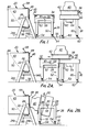
- Figs. 2A-2H The operation of the plastic molding apparatus will now be described with reference to Figs. 2A-2H.
- the mold 40 and platen 38 are slid together from the transport unit 36 onto the heat box 28 until the lower plate 41 engages the U-shaped guides 32 on all three sides.
- the heat box 28, with the platen 38 and mold 40 are pivoted together to arrange the mold in alignment with the opening 46 of the container 20.
- the transport unit 26 is then moved toward the left along the track 56 to bring the mold 40 inside the container 20.
- Fig. 2A the mold 40 and platen 38 are slid together from the transport unit 36 onto the heat box 28 until the lower plate 41 engages the U-shaped guides 32 on all three sides.
- the heat box 28, with the platen 38 and mold 40 are pivoted together to arrange the mold in alignment with the opening 46 of the container 20.
- the transport unit 26 is then moved toward the left along the track 56 to bring the mold 40 inside the container 20.
- the flange 42 at the base of the mold 40 is brought into flat engagement with the sealing strip 48 and the entire heat box, platen and mold combination are attached to the container 20 by clamping hooks 68.
- the transport unit 26 is then rolled away from the assembled apparatus to permit rotation of the container.
- the combined heat box, platen, mold and container are next rotated through a 90° arc about the pivot shafts 22 so that the opening 46 and mold 40 are at the bottom of the container 20, as shown in Fig. 2D.
- the particulate plastic material indicated by the dashed lines 50 then falls by gravity toward the opening 46 of the container 20 and surrounds the mold 40.
- heat is applied to the inside surface of the mold 40 from the heat box 28, in a manner to be described below.
- the application of heat causes a layer of the particulate material to fuse together and attach itself to the outside surface of the mold 40.
- the combined heat box, platen, mold and container are rotated together through a 180° arc about the shafts 22, as shown in Fig. 2E.
- This movement causes that portion of the plastic particulate material which has not become fused to fall toward what is now the bottom of the container 20, revealing a fused layer 70 of plastic material on the mold 40 having an inner configuration which corresponds to the configuration of the outer surface of the mold.
- heat is applied for a shorter period of time so as to "fuse out" the outside surface of the fused plastic material, allowing it to become smoother.
- the combined pivoted apparatus is rotated again through a 90° arc to return the parts to the same relative position as initially when the mold, platen and heat box were clamped to the container 20.
- the transport unit 26 is then brought into position so as to support the pivot shaft ends 30 on opposite sides of the heat box in the recesses 58.
- the clamping hooks 68 are released and the assembled mold 40, including a newly fused article 70 of plastic, the platen 38 and the heat box 28 are withdrawn away from the container 20 as shown in Fig. 2F.
- the assembled mold, platen and heat box are pivoted through a 90° arc so that the mold is positioned atop the platen and heat box.
- the mold and platen are then moved horizontally onto the second transport unit 36, as indicated in Fig. 2G, and transport unit 36 is wheeled away from the vicinity of the container 20 and the transport unit 26 so that the mold 40 and fused article 70 may be further cooled.
- the fan in the housing 64 circulates room air upwards into the cavity of the mold 40. This air contacts the warm inner surface of mold and draws heat from the mold and from the hot plastic material surrounding the mold. The fused article 70 is thereby cooled to a point at which the article may be removed from the mold.
- Fig. 3 shows a fan 65 located in the housing 64 at center of the transport unit 36. Openings 71 in the housing 64 permit room air to be drawn into the fan 65. The thus-propelled air is guided by baffle plates 72 in the platen 38 towards the inner surface of the mold 40, and exits through openings 74.
- the air inlet 66 is connected via a suitable hose 75 to a source of compressed air, or other gas. This air is directed to the outside surface of the mold, thereby lifting off the plastic article, as shown in Fig. 2H.
- the air inlet 66 communicates via tubes 76 with an opening 78 at the top center of the mold 40.
- the opening 78 is normally closed by a valve head 80, which is attached to a valve stem 82.
- a helical spring 84 concentric with the stem 82, acts on a valve stem plate 86 to bias the valve head 80 in a direction closing the opening 78.
- the application of air under pressure to the air inlet 66 overcomes the force of the spring 84, disloges valve head 80 from the opening 78, and permits the air to enter the space between the outer surface of mold 40 and the inner surface of plastic article 70. If for some reason the valve head 80 is stuck, it may be dislodged by tapping gently with a hammer on the stem end 88.
- valve apparatus for applying compressed air is shown in Figs. 4 and 5 as comprising only a single opening 78 and valve head 80, it will be appreciated that air may be directed to a plurality of openings, with corresponding valve heads, located at various points on the outer surface of the mold.
- the platen 38 is constructed from two horizontal metal plates 41 and 92 which are separated and held in position by four vertical metal plates 90 forming a box.
- the plates 41, 90 and 92 are joined together by welds 94 along their edges.
- Both horizontal plates 41 and 92 have openings at their centers to permit air to pass freely into the interior of the mold 40.
- the base of the metal mold 40 is bolted to the upper surface of the plate 92.
- An upper flange 42 which is made of a non-heat conductive material such as wood, surrounds the mold at some distance therefrom and is bolted to the plate 92 together with the mold base.
- the space between the inside edge of the flange 42 and the lowermost non-horizontal portion of the mold 40 is filled, in part, by a circumferential strip 96 of non-adhering material such as Teflon. This arrangement leaves a small space 98 immediately adjacent to the base of the mold 40 which may be filled with particulate material during the molding process.
- a sharp clean line about the open edge of the finished, molded article is created by the inner face of the strip 96 of non-adhering material.
- Fig. 6 shows the structure of the heat box 28 in detail.
- the internal and external surfaces of this box are made of metal sheet 100 which surrounds insulation 102.
- the upper end of the box is provided with U-shaped guides 32 for the base plate 41 of the mold platen 38.
- a fan 104 is centrally positioned to force air through the open face of the box, in the directions indicated by the arrows, with the assistance of baffles 108.
- Heating elements 110 are positioned below the blades of a fan 104 so that the fan forces heated air up into the interior of the mold 40 when the mold is positioned above the open face of the heat box. These heating elements are controlled by thermocouples 112 arranged in the path of air flowing through the box. Electrical leads 114 supply power to the fan motor 116 and to the heating elements 110. Another cable 118 carries control signals from the thermocouples 112.
- the electric circuit for the heat box 28 is connected to operate as follows: Electrical power is supplied to the fan motor 116 through a timer which turns the motor on during the precise periods that heat is to be applied to the mold.
- the heating elements 110 are separately connected to the power source when the fan is on through switches controlled by the thermocouples 112. When rapid heating of the mold 40 is desired, as when the mold has first been inserted into the container 20, power is applied to all of the heating elements. When the air circulating through the heat box reaches a first temperature determined by one thermocouple, some of the heating elements (for example, one-half of these elements) are disconnected from the power source while the remaining elements are left connected.
- thermocouples 112 are each set to respond at one of the two different temperatures, thereby providing signals on the electrical leads 118 to control the power to the heating elements 110.
- FIG. 7 illustrates an alternative arrangement of a heat- box with eight banks of heating elements 120 arranged in pairs around the fan 104.
- Two thermocouples 112 are provided as in the embodiment of Fig. 6, in the path of air that recirculates through the box.
- Rectangular posts 122 are provided at the four corners of the box so that the air is constrained to flow through the heating elements 120.
- the container 20, and a mechanism for rotating the container is illustrated in Fig. 8.
- the container has four side walls 43 and rear wall 44.
- the front of the container 46 is open and is provided with a resilient seal 48 made of foam rubber or cork, for example, around its face edge.
- Clamping hooks 68 are provided on at least two opposite sides near the front opening.
- Attached to the container, and extending outwardly on opposite sides of a horizontal plane are two axially aligned shafts 22.
- the shafts 22 provide support for the container and permit the container to rotate in the manner described above.
- Rotation of the container is effected by a motor 124, a speed-reduction gear box 126 and a chain and sprocket drive 128.
- Electrical power is supplied to the heat box, that rotates with the container 20, through suitable rotating collectors 130 and stationary brushes 132.
- the power is switched on and off by a control box 134 which contains one or more timers 136 and receives control signals from the heat box thermocouples on line 118.
- the particulate plastic material 50 in the container 20 is moved about within the container as it is rotated.
- the container is provided with a perforated baffle 138 which extends from one side wall to the other diagonally downward from the upper corner of the rear wall 44.
- Another identical baffle which is covered by the particulate plastic material 50 and is therefore not shown in Fig. 8, extends diagonally upward from the lower corner of the rear wall 44.
- the precise position of these two baffles 138 is shown in cross section in Fig. 9A.
- the purpose of the baffles 138 is to control the flow of particulate material onto the mold as the container 20 is rotated. Depending upon the type of mold, these baffles improve the distribution of the particulate material over the mold surface.
- Fig. 9B shows a container 20 having a door 140 in its rear wall 44 to permit particulate plastic material to be removed and inserted when the front opening 146 is closed by the mold and mold platen assembly.
- This permits different plastic materials to be inserted into the container without removing the mold so as to build up layers of different plastics on the mold surface, thereby forming a laminated plastic article.
- a plastic article which is white on the inside and black on the outside may be formed by molding first with white particulate material, replacing the white material with black material through the trap door, and then molding with the black material.
- Fig. 9C shows another embodiment of the container 20 which is provided with an insert 142 removably mounted inside.
- This insert reduces the interior volume of the container to adjust for molds of small size.
- the insert 142 may be removed by detaching the latches 144 on the opposite side walls.
- Fig. 9D shows a further embodiment of the container 20 which is provided with a vibrating mechanism 146.
- This mechanism 146 imparts vibrational energy to the container walls so that the particulate plastic material may be agitated as it settles over the mold. Such vibration causes the material to evenly surround the mold and is particularly advantageous when the mold surface includes indentations or projections.
- Fig. 9E shows an embodiment of the container 20 which is provided with heating coils 148 adjacent its inner surface.
- These coils may be constructed as tubes that carry a hot liquid or gas, such as steam, or they may simply be electrical heating elements connected to a suitable power source.
- the container may be made of wood or some other insulating sheet material, it may also be constructed as a laminate with separate insulation as shown in the figure. The application of heat to the container makes it possible to maintain the particulate plastic material within the container at a temperature close to the fusing temperature to reduce the heating time when the mold is inserted.
- Fig. 9F shows another embodiment of the container 20, this time in front view.
- the figure shows the seal 48 and two clamping hooks 68.
- the clamping hooks each comprise a handle pivotally mounted on a side wall of the container 20 adjacent to the front opening 46 and a hook member pivotably attached to the handle between the handle ends.
- guide plates 150 attached to opposite walls of the container, for aligning the mold platen with the container.
- the guide plates 150 are each provided with ribs 152 extending perpendicular to the plane of the front opening of the container.
- Mating guide plates 154 shown in dashed lines in Fig. 9F, are provided on the mold platen and extend forward to engage the guide plates 150 as the mold is inserted into the container.
- the mold 40 which may assume virtually any configuration, is preferably made of welded aluminum due to its strength and high heat conductivity. However, any other metal, both sheet metal and cast metal may be used. In fact, thermosetting plastic, although not nearly as heat conductive as metal, may be also used to form the mold.
- Fig. 10A illustrates one mold 40 in cross section having internal baffles 156 to direct the heated air towards specific areas, such as the corners of the mold.
- baffles By means of such baffles it is possible to "place” the heat and thereby control the thickness of the finished plastic article at specific locations.
- Fig. 10B shows a mold 40 with an adjustable flange ring 158 temporarily welded at a desired height on the sides of the mold. With such a flange, it is possible to produce plastic molded articles of any prescribed depth using a single original mold.
- Heat insulation 160 may be provided on the inner and/or outer surface of the mold so that heat is preferentially placed where the molded article is to be formed.
- Fig. 10C shows a male mold 40 for a container which will have, when molded, a narrowed neck portion and an enlarged bottom portion corresponding to the regions 162 and 164 of the mold, respectively.
- This mold configuration is typical of many types of male molds having shaped sides which would not permit a plastic molded article, when formed, to simply slide off the top of the mold.
- Other mold configurations which present this same problem are those having an inwardly extending recess, at the base for example, or outwardly extending projections along the mold sides.
- Figs. llA and 11B illustrate, in bottom view, rectangular and cylindrical molds, respectively, which overcome the problem of separation of the plastic molded article and the mold when the mold has a configuration of the type described above.
- the mold is formed as a collapsible, segmented unit, which may be taken apart when the molding process is complete and removed from the inside of the plastic molded article.
- the mold is formed of four segments 166, 168, 170 and 172, held in position, during molding, by two adjustable bars 174 and 176.
- the mold segments 168 and 172 are first drawn inward, away from the inner surface of the plastic molded article, and removed from the article. Thereafter, the other two segments 166 and 170 are similarly drawn inward and removed. Consequently, the male mold utilized in the practice of the present invention may assume virtually any configuration, and need not be restricted by the requirement that the plastic molded article is to be slid off the outside surface of the mold.
- Figs. 12 and 13 illustrate how the present invention may be used to form plastic molded articles having holes or openings therein.
- the hollow heat conductive mold core 40 may be provided with projections of any shape, anywhere on its surface, made of non-heat conductive material such as Teflon or Nylon. While Fig. 12 shows two large projections 178, Fig. 13 shows a large number of small projections 180 arranged around the lateral sides of the mold core 40.
- the projections are attached to the mold core by means of bolts 182 and nuts 184 in the embodiment shown in Fig. 13. The projections must be unbolted and detached from the mold core before the plastic molded article may be removed.
- Figs. 14A and 14B illustrate how a mold 40 may be provided with heat conductive attachments 186 and 188, respectively, for producing plastic molded articles with undercuts or recesses in their interior surface.
- These attachments 186 and 188 are preferably made of metal, such as aluminum or steel. They are formed in the precise shape desired for the interior surface of the molded article and attached to the mold 40 in such a way that they can be detached when the article is to be removed from the mold.
- the attachments 186 are connected to the mold by means of bolts 190 which may be removed, prior to removal of the plastic molded article, by unscrewing them from inside the mold.
- bolts 190 which may be removed, prior to removal of the plastic molded article, by unscrewing them from inside the mold.
- the attachments 188 are made of magnetizable material such as iron or steel and are held in position by permanent magnets 192 embedded in the exterior surface of the mold 40.
- the attachments 186 and 188 are removed from the mold 40 together with the plastic molded article, and then__are removed by hand from inside the article. If desired, these attachments may be allowed to remain in the plastic molded article as reinforcements.
- Fig. 15 shows a single mold platen 38 adapted to carry a plurality of individual molds 194.
- a single upper flange 42 of non-heat conductive material such as wood or plastic is provided to define the areas in which the particulate plastic material will be heated and fused to the individual molds.
- a platen and molds of this type With a platen and molds of this type, a plurality of molded articles may be formed in one heating and cooling cycle.
- the manner of attaching the molds 194 to the platen 38 is completely analogous to the arrangement described above and illustrated in Fig. 5.
- Figs. 16 and 17 illustrate another embodiment of plastic molding apparatus according to the invention which is capable of handling large molds for forming large plastic containers and the like.
- the mold 40 illustrated in these figures is approximately 1 metre wide and 1.2 metres.
- the container 20 is appropriately dimensioned to receive this mold.
- the heat box is carried on a transport unit 196 having wheels 198 arranged on a track 200 fixed to the floor.
- the transport unit is provided with a pair of support arms 202 which grasp the heat box 28 by pinions 204 on either side and raise it up to the mounting position shown in Fig. 17.
- the mold, mold platen and heat box combination are prevented from rotating counterclockwise by a block 212 on the side of the heat box.
- the container 20 is provided with a vibrating unit 216 for imparting vibrational energy to the container; contactors 218 for 1 supplying electrical power from the container to the heat box via mating contactors 220; and guide plates 222 on opposite sides of the type described above and shown in Fig. 9F.
- the guide plates 222 mate with the corresponding guide plates 224 on opposite sides of the mold.
- Fig. 18 illustrates an embodiment of apparatus according to the present invention which serves to form plastic molded articles in a continuous process.
- the apparatus includes a conveyor 226 to which are connected a number of units, each comprising a mold 228 and mold platen 230.
- the conveyor moves intermittently to propel the mold and platen units from one process stage to the next.
- particulate plastic material 234 is loaded onto the top of the mold and platen. Excess material drops into a hopper 236 and is carried off by a conveyor belt 238. This excess material is returned to a hopper 240 for delivery to the stage 232 by a conveyor 242.
- the mold and platen unit is vibrated by a vibrating device 246.
- the mold and platen unit rides up over this vibrating device when it is moved to this second stage.
- heat is applied to the interior of the mold from a heating unit 250.
- This heating unit operates in substantially the same manner as the heat box 28 described above and shown, for example, in Figs. 6 and 7.
- the mold and platen unit is moved to the next stage 252 at which the excess particulate material is removed. This material falls into a hopper 254 and is carried away by a conveyor belt 256 and returned to the hopper 240. Thereafter, the mold and platen unit is moved to the fuse-out stage 258 where it again receives heat from the heating unit 250. Subsequently, it is moved to the cooling stage 260 and cool air is blown into the interior of the mold by a cooling unit 262.
- This cooling unit may comprise a fan and baffles as are described above in connection with Fig. 3.
- the mold and platen unit is moved to the ejection stage 264 at which air is directed to the outside surface of the mold to remove the molded plastic article.
- the article drops onto a conveyor belt 266 which moves it away from the conveyor 226.
- a suitable shroud to prevent the particulate plastic material from entering the atmosphere.
- the particulate plastic material utilized in forming the molded article may be any thermoplastic which forms a solid at room temperature.
- Preferred materials, and suggested sources for these materials are as follows: Polyethylene - Chemplex, USI Chemicals, or equivalent.
- the particle size of the plastic material has a preferred upper limit of approximately 200 microns (diameter). Larger particles result in an undesirably coarse product.
- the thermoplastic material preferably has a relatively low melt index because, in general, the longer the time it takes to form the plastic article, the stronger it will be. A melt index in the range of .5 to 20 is preferred. As explained above, the plastic material surrounding the mold is heated to a temperature between the fusion and melting temperatures of the particular material used. The longer this temperature is applied to the mold while the particulate plastic material surrounds the mold, the thicker the molded article will be.
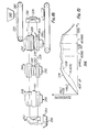
- Fig. 19 shows a time-temperature diagram for a typical molding process.
- the mold temperature is indicated by a solid line 226, whereas the temperature of the plastic immediately surrounding the mold is indicated by a dashed line 228.
- the particulate plastic material starts at substantially room temperature, although as has been explained above in connection with Fig. 9E, the plastic material may be maintained at a temperature slightly below its fusion temperature to shorten the warm-up time.
- the mold and the surrounding plastic is heated rapidly to a temperature above the fusion temperature of the material. If the temperature were allowed to continue to rise to above the melting temperature of the material, the plastic would turn to a liquid at the surface of the mold and flow down to the base of the mold. Consequently, it is important to maintain the temperature of the mold below the melting temperature of the plastic.
- the mold is maintained at a substantially constant temperature (usually cycling betwen two slightly different temperatures as described above in connection with Figs. 6 and 7). During this "dwell" time, the particulate plastic material at the surface of the mold fuses together. The longer this temperature is maintained with the particulate material surrounding the mold, the thicker the plastic article will be because the heat of the mold is conducted outward through the plastic material and fuses material at an ever-increasing distance from the mold.
- the mold When the desired thickness of the article is reached, the mold is rotated to remove the loose particulate material from the fused molded article. Thereafter, the temperature is maintained on the mold to "fuse out” the article, causing the outer surface of the article to become smoother.
- heat supplied to the interior of the mold is switched off and the mold, with its surrounding plastic article,--is removed from the container or from the stage at which the fuse-out heat is applied.
- a cooling medium such as air, is applied to the interior of the mold to rapidly cool the mold and the surrounding article. Once the article is brought down to room temperature it is removed from the mold.
- FIG. 19 shows rapid cooling of the mold and article, internal stresses in the article may be minimized by allowing it to cool slowly. If the article is thus annealed it will exhibit no "memory"; i.e., it will always return to its original shape after warping or bending.
- a foaming agent such as Celogen, which is available commercially from U.S. Royal, may be added at the rate of 500 grams for each 100 kg of plastic to create pores in the plastic molded article.
- laminated articles may also be formed by carrying out the process according to the present invention using several different plastic materials. For example, a thin layer of non-porous plastic may be formed on the side of the mold, followed by a layer of foamed plastic, thereby producing a light container with a non-porous interior surface. The sequential process steps of forming different layers of plastic on the mold may be carried out either by replacing material through a trap door in a single container as shown in Fig. 9B, or by successively inserting the mold in a plurality of containers, each with a different plastic.material.
- a non-stick coating of Teflon or silicone may be sprayed or painted onto the outer surface of the mold before it is inserted into the container.
- Such coatings are commercially available and are known as a "mold release".
- the mold or the container are preferably subjected to a mechanical vibration between the time that the particulate plastic material is poured over the mold and the time that the heat is applied to the interior of the mold.
- a mechanical vibration between the time that the particulate plastic material is poured over the mold and the time that the heat is applied to the interior of the mold.
- Such vibration disperses and distributes the particulate material evenly around the mold. It has been found that 50 or 60 Hz vibration for a period of about two minutes is sufficient for this purpose.
- the mold with the fused article is removed from the container and rapidly cooled by directing air at room temperature against the inner surface of the mold. Finally, the article is removed from the mold and sanded, where necessary, to eliminate rough edges.
Landscapes
- Engineering & Computer Science (AREA)
- Mechanical Engineering (AREA)
- Moulds For Moulding Plastics Or The Like (AREA)
- Processing And Handling Of Plastics And Other Materials For Molding In General (AREA)
- Moulding By Coating Moulds (AREA)
- Casting Or Compression Moulding Of Plastics Or The Like (AREA)
- Molding Of Porous Articles (AREA)
Priority Applications (1)
| Application Number | Priority Date | Filing Date | Title |
|---|---|---|---|
| AT79302296T ATE10600T1 (de) | 1978-10-23 | 1979-10-22 | Verfahren und vorrichtung zum formen von gegenstaenden aus thermoplastischem kunststoff unter verwendung von granulat oder pulver. |
Applications Claiming Priority (2)
| Application Number | Priority Date | Filing Date | Title |
|---|---|---|---|
| US953707 | 1978-10-23 | ||
| US05/953,707 US4431397A (en) | 1978-10-23 | 1978-10-23 | Apparatus for producing molded plastic articles |
Publications (2)
| Publication Number | Publication Date |
|---|---|
| EP0010914A1 true EP0010914A1 (de) | 1980-05-14 |
| EP0010914B1 EP0010914B1 (de) | 1984-12-05 |
Family
ID=25494426
Family Applications (1)
| Application Number | Title | Priority Date | Filing Date |
|---|---|---|---|
| EP79302296A Expired EP0010914B1 (de) | 1978-10-23 | 1979-10-22 | Verfahren und Vorrichtung zum Formen von Gegenständen aus thermoplastischem Kunststoff unter Verwendung von Granulat oder Pulver |
Country Status (7)
| Country | Link |
|---|---|
| US (1) | US4431397A (de) |
| EP (1) | EP0010914B1 (de) |
| JP (1) | JPS5597917A (de) |
| AT (1) | ATE10600T1 (de) |
| CA (1) | CA1151830A (de) |
| DE (1) | DE2967323D1 (de) |
| IL (1) | IL58549A (de) |
Cited By (1)
| Publication number | Priority date | Publication date | Assignee | Title |
|---|---|---|---|---|
| GB2121345A (en) * | 1982-05-28 | 1983-12-21 | Glasdon Ltd | Method of rotary moulding a plastics article |
Families Citing this family (21)
| Publication number | Priority date | Publication date | Assignee | Title |
|---|---|---|---|---|
| US4560335A (en) * | 1983-11-07 | 1985-12-24 | Cordova Elmer R | Vault machine |
| DE3520152A1 (de) * | 1985-06-05 | 1986-12-18 | Ymos Aktiengesellschaft Industrieprodukte, 6053 Obertshausen | Verfahren und vorrichtung zum herstellen einer kunststoffhaut |
| CA1204262A (en) * | 1985-08-16 | 1986-05-13 | James S. Sheffield | Injection mold apparatus with gas ejection |
| JPH049143Y2 (de) * | 1986-04-11 | 1992-03-06 | ||
| US5588530A (en) * | 1989-08-09 | 1996-12-31 | Southpac Trust International, Inc. | Wrapping material for wrapping a floral grouping having staggered strips of adhesive material applied thereto and method |
| US5911943A (en) * | 1997-07-07 | 1999-06-15 | Minghetti; Ettore | Method of thermoforming a sheet material |
| US6010325A (en) * | 1998-04-08 | 2000-01-04 | Lawrence Equipment | Pizza die |
| US6589470B2 (en) | 1999-04-26 | 2003-07-08 | Robert P. Fried | Process for producing molded plastic articles |
| CN1974169B (zh) * | 2001-02-05 | 2012-02-29 | 3Dm全球有限公司 | 塑料复合制品 |
| DE102004054098A1 (de) | 2004-11-09 | 2006-05-11 | Kiefel Ag | Verfahren und Vorrichtung zur Herstellung von Kunststoff-Formfolien |
| US7429026B2 (en) * | 2005-12-05 | 2008-09-30 | Romportl Robert H | Concrete block technology |
| DE102005062434A1 (de) * | 2005-12-23 | 2007-07-05 | Matthias Falkenberg | Verfahren und Vorrichtung zum Zerkleinern von kunststoffhaltigem Schüttgut |
| FR2907638B1 (fr) * | 2006-10-30 | 2009-01-23 | Jacquet Panification | Procede de fabrication de produits de boulangerie,tels que pain de mie et produits cuits ainsi obtenus |
| US8246341B2 (en) * | 2007-12-27 | 2012-08-21 | Nike, Inc. | Mold rotator |
| US20110291323A1 (en) * | 2010-05-25 | 2011-12-01 | High Concrete Group Llc | Method and apparatus for positioning a conduit guide in a moldable material prior to pouring the material into a form |
| WO2012140474A1 (en) * | 2011-04-13 | 2012-10-18 | Partes S.R.L. | Process to mould objects with a dust material |
| GB201113655D0 (en) * | 2011-08-08 | 2011-09-21 | Surface Generation Ltd | Tool temperature control |
| GB201303845D0 (en) * | 2013-03-04 | 2013-04-17 | Surface Generation Ltd | Mould Tool Temperrature Control |
| DE102014206500B4 (de) * | 2014-04-04 | 2024-10-31 | Bayerische Motoren Werke Aktiengesellschaft | Werkzeug zur Herstellung eines Faserverbundbauteils |
| US10576680B2 (en) | 2015-11-19 | 2020-03-03 | The Boeing Company | Modular thermoforming system |
| US11110631B2 (en) * | 2019-07-02 | 2021-09-07 | The Boeing Company | Systems, cure tools, and methods for thermally curing a composite part |
Citations (6)
| Publication number | Priority date | Publication date | Assignee | Title |
|---|---|---|---|---|
| DE853998C (de) * | 1950-10-20 | 1952-10-30 | Hoechst Ag | Verfahren und Vorrichtung zur Herstellung von UEberzuegen auf Werkstuecken, Rohren od. dgl. |
| DE1554880A1 (de) * | 1962-09-07 | 1970-01-22 | Siemens Elektrogeraete Gmbh | Verfahren und Anordnung zur Herstellung von Kunststoffkoerpern |
| DE1949125A1 (de) * | 1968-11-04 | 1970-05-27 | Lars Ringdal | Vorrichtung an Maschine zur Herstellung von Gegenstaenden aus Plastik |
| DE1554910B2 (de) * | 1965-02-27 | 1971-03-11 | Sumitomo Chemical Co Ltd , Osaka (Japan), Vjtr Jung, E , Dr Chem Dr phil , Vossius, V , Dipl Chem Dr rer nat , Pat Anwalte, 8000 München | Verfahren zum herstellen von poroesen kunststoff formteilen |
| DE1554784B2 (de) * | 1965-02-23 | 1973-02-15 | Mitsui Petrochemical Industries Ltd, Tokio | Wirbelsinterverfahren zum herstellen von formgegenstaenden aus thermoplastischen pulverfoermigen materialien |
| GB1337962A (en) * | 1969-11-28 | 1973-11-21 | Aquitaine Total Organico | Containers |
Family Cites Families (3)
| Publication number | Priority date | Publication date | Assignee | Title |
|---|---|---|---|---|
| US2907070A (en) * | 1955-03-25 | 1959-10-06 | Carroll H Van Hartesveldt | Temperature control apparatus for a mold |
| US3177275A (en) * | 1960-11-10 | 1965-04-06 | Ivan G Brenner | Method and means for producing fibrous articles |
| SE324431B (de) * | 1966-05-27 | 1970-06-01 | Bofors Ab |
-
1978
- 1978-10-23 US US05/953,707 patent/US4431397A/en not_active Expired - Lifetime
-
1979
- 1979-10-22 EP EP79302296A patent/EP0010914B1/de not_active Expired
- 1979-10-22 DE DE7979302296T patent/DE2967323D1/de not_active Expired
- 1979-10-22 CA CA000338096A patent/CA1151830A/en not_active Expired
- 1979-10-22 AT AT79302296T patent/ATE10600T1/de not_active IP Right Cessation
- 1979-10-23 JP JP13695279A patent/JPS5597917A/ja active Pending
- 1979-10-24 IL IL58549A patent/IL58549A/xx unknown
Patent Citations (6)
| Publication number | Priority date | Publication date | Assignee | Title |
|---|---|---|---|---|
| DE853998C (de) * | 1950-10-20 | 1952-10-30 | Hoechst Ag | Verfahren und Vorrichtung zur Herstellung von UEberzuegen auf Werkstuecken, Rohren od. dgl. |
| DE1554880A1 (de) * | 1962-09-07 | 1970-01-22 | Siemens Elektrogeraete Gmbh | Verfahren und Anordnung zur Herstellung von Kunststoffkoerpern |
| DE1554784B2 (de) * | 1965-02-23 | 1973-02-15 | Mitsui Petrochemical Industries Ltd, Tokio | Wirbelsinterverfahren zum herstellen von formgegenstaenden aus thermoplastischen pulverfoermigen materialien |
| DE1554910B2 (de) * | 1965-02-27 | 1971-03-11 | Sumitomo Chemical Co Ltd , Osaka (Japan), Vjtr Jung, E , Dr Chem Dr phil , Vossius, V , Dipl Chem Dr rer nat , Pat Anwalte, 8000 München | Verfahren zum herstellen von poroesen kunststoff formteilen |
| DE1949125A1 (de) * | 1968-11-04 | 1970-05-27 | Lars Ringdal | Vorrichtung an Maschine zur Herstellung von Gegenstaenden aus Plastik |
| GB1337962A (en) * | 1969-11-28 | 1973-11-21 | Aquitaine Total Organico | Containers |
Cited By (1)
| Publication number | Priority date | Publication date | Assignee | Title |
|---|---|---|---|---|
| GB2121345A (en) * | 1982-05-28 | 1983-12-21 | Glasdon Ltd | Method of rotary moulding a plastics article |
Also Published As
| Publication number | Publication date |
|---|---|
| IL58549A0 (en) | 1980-01-31 |
| US4431397A (en) | 1984-02-14 |
| CA1151830A (en) | 1983-08-16 |
| ATE10600T1 (de) | 1984-12-15 |
| DE2967323D1 (en) | 1985-01-17 |
| EP0010914B1 (de) | 1984-12-05 |
| IL58549A (en) | 1983-07-31 |
| JPS5597917A (en) | 1980-07-25 |
Similar Documents
| Publication | Publication Date | Title |
|---|---|---|
| EP0010914B1 (de) | Verfahren und Vorrichtung zum Formen von Gegenständen aus thermoplastischem Kunststoff unter Verwendung von Granulat oder Pulver | |
| US6589470B2 (en) | Process for producing molded plastic articles | |
| US3217078A (en) | Process for molding hollow articles from thermoplastic materials | |
| US7052270B2 (en) | Post mold cooling apparatus | |
| US4552715A (en) | Process for producing a molded skin product | |
| JPH0564822A (ja) | プラスチツク製成形品の製造装置及び方法 | |
| EP0908292A4 (de) | Verfahren und vorrichtung zum herstellen von blasgeformten gegenständen | |
| US3636151A (en) | Method for producing a hollow doublewall plastic article | |
| US2691798A (en) | Molding apparatus | |
| US3369274A (en) | Moulding machine | |
| JPH0671689A (ja) | 自動成形法 | |
| JPH07115367B2 (ja) | プラスチック成形シートを製造するための装置 | |
| US3683062A (en) | Rotational casting method | |
| US3997649A (en) | Method of rotational molding a hollow article | |
| CA1291617C (en) | Powder slush process and apparatus for making plastic articles | |
| US3732051A (en) | Molding apparatus for producing resinous thermoplastic articles | |
| Bruins | Basic principles of rotational molding | |
| JPH066302B2 (ja) | パウダースラッシュ成形装置 | |
| JPH0257762B2 (de) | ||
| CA1075867A (en) | Method of rotational molding a hollow article | |
| JPH09248832A (ja) | 加熱炉 | |
| JPH044924B2 (de) | ||
| JPH061385Y2 (ja) | 表皮材成形装置 | |
| JPS6233060B2 (de) | ||
| GB2123741A (en) | Manufacturing moulded sheet material |
Legal Events
| Date | Code | Title | Description |
|---|---|---|---|
| PUAI | Public reference made under article 153(3) epc to a published international application that has entered the european phase |
Free format text: ORIGINAL CODE: 0009012 |
|
| AK | Designated contracting states |
Designated state(s): AT BE CH DE FR GB IT LU NL SE |
|
| 17P | Request for examination filed |
Effective date: 19801110 |
|
| RAP1 | Party data changed (applicant data changed or rights of an application transferred) |
Owner name: NOW PLASTICS CORPORATION |
|
| GRAA | (expected) grant |
Free format text: ORIGINAL CODE: 0009210 |
|
| AK | Designated contracting states |
Designated state(s): AT BE CH DE FR GB IT LU NL SE |
|
| PG25 | Lapsed in a contracting state [announced via postgrant information from national office to epo] |
Ref country code: SE Effective date: 19841205 Ref country code: NL Effective date: 19841205 Ref country code: IT Free format text: LAPSE BECAUSE OF FAILURE TO SUBMIT A TRANSLATION OF THE DESCRIPTION OR TO PAY THE FEE WITHIN THE PRESCRIBED TIME-LIMIT;WARNING: LAPSES OF ITALIAN PATENTS WITH EFFECTIVE DATE BEFORE 2007 MAY HAVE OCCURRED AT ANY TIME BEFORE 2007. THE CORRECT EFFECTIVE DATE MAY BE DIFFERENT FROM THE ONE RECORDED. Effective date: 19841205 Ref country code: FR Free format text: THE PATENT HAS BEEN ANNULLED BY A DECISION OF A NATIONAL AUTHORITY Effective date: 19841205 Ref country code: CH Effective date: 19841205 Ref country code: BE Effective date: 19841205 Ref country code: AT Effective date: 19841205 |
|
| REF | Corresponds to: |
Ref document number: 10600 Country of ref document: AT Date of ref document: 19841215 Kind code of ref document: T |
|
| REF | Corresponds to: |
Ref document number: 2967323 Country of ref document: DE Date of ref document: 19850117 |
|
| REG | Reference to a national code |
Ref country code: CH Ref legal event code: PL |
|
| NLV1 | Nl: lapsed or annulled due to failure to fulfill the requirements of art. 29p and 29m of the patents act | ||
| EN | Fr: translation not filed | ||
| PLBE | No opposition filed within time limit |
Free format text: ORIGINAL CODE: 0009261 |
|
| STAA | Information on the status of an ep patent application or granted ep patent |
Free format text: STATUS: NO OPPOSITION FILED WITHIN TIME LIMIT |
|
| PG25 | Lapsed in a contracting state [announced via postgrant information from national office to epo] |
Ref country code: LU Free format text: LAPSE BECAUSE OF NON-PAYMENT OF DUE FEES Effective date: 19851031 |
|
| 26N | No opposition filed | ||
| GBPC | Gb: european patent ceased through non-payment of renewal fee | ||
| PG25 | Lapsed in a contracting state [announced via postgrant information from national office to epo] |
Ref country code: DE Effective date: 19880701 |
|
| PG25 | Lapsed in a contracting state [announced via postgrant information from national office to epo] |
Ref country code: GB Effective date: 19881118 |