EP0011012A1 - Zentriervorrichtung für eine optische Faser in einer Zwinge und Zwinge mit einer optischem Faser die mit dieser Vorrichtung zentriert worden ist - Google Patents
Zentriervorrichtung für eine optische Faser in einer Zwinge und Zwinge mit einer optischem Faser die mit dieser Vorrichtung zentriert worden ist Download PDFInfo
- Publication number
- EP0011012A1 EP0011012A1 EP79400758A EP79400758A EP0011012A1 EP 0011012 A1 EP0011012 A1 EP 0011012A1 EP 79400758 A EP79400758 A EP 79400758A EP 79400758 A EP79400758 A EP 79400758A EP 0011012 A1 EP0011012 A1 EP 0011012A1
- Authority
- EP
- European Patent Office
- Prior art keywords
- dihedron
- fiber
- cylinders
- optical fiber
- shims
- Prior art date
- Legal status (The legal status is an assumption and is not a legal conclusion. Google has not performed a legal analysis and makes no representation as to the accuracy of the status listed.)
- Granted
Links
Images

Classifications
-
- G—PHYSICS
- G02—OPTICS
- G02B—OPTICAL ELEMENTS, SYSTEMS OR APPARATUS
- G02B6/00—Light guides; Structural details of arrangements comprising light guides and other optical elements, e.g. couplings
- G02B6/24—Coupling light guides
- G02B6/36—Mechanical coupling means
- G02B6/38—Mechanical coupling means having fibre to fibre mating means
- G02B6/3807—Dismountable connectors, i.e. comprising plugs
- G02B6/3833—Details of mounting fibres in ferrules; Assembly methods; Manufacture
- G02B6/3834—Means for centering or aligning the light guide within the ferrule
- G02B6/3841—Means for centering or aligning the light guide within the ferrule using rods, balls for light guides
-
- G—PHYSICS
- G02—OPTICS
- G02B—OPTICAL ELEMENTS, SYSTEMS OR APPARATUS
- G02B6/00—Light guides; Structural details of arrangements comprising light guides and other optical elements, e.g. couplings
- G02B6/24—Coupling light guides
- G02B6/36—Mechanical coupling means
- G02B6/38—Mechanical coupling means having fibre to fibre mating means
- G02B6/3807—Dismountable connectors, i.e. comprising plugs
- G02B6/3833—Details of mounting fibres in ferrules; Assembly methods; Manufacture
- G02B6/3834—Means for centering or aligning the light guide within the ferrule
- G02B6/3838—Means for centering or aligning the light guide within the ferrule using grooves for light guides
-
- G—PHYSICS
- G02—OPTICS
- G02B—OPTICAL ELEMENTS, SYSTEMS OR APPARATUS
- G02B6/00—Light guides; Structural details of arrangements comprising light guides and other optical elements, e.g. couplings
- G02B6/24—Coupling light guides
- G02B6/36—Mechanical coupling means
- G02B6/38—Mechanical coupling means having fibre to fibre mating means
- G02B6/3807—Dismountable connectors, i.e. comprising plugs
- G02B6/3833—Details of mounting fibres in ferrules; Assembly methods; Manufacture
- G02B6/3834—Means for centering or aligning the light guide within the ferrule
- G02B6/3838—Means for centering or aligning the light guide within the ferrule using grooves for light guides
- G02B6/3839—Means for centering or aligning the light guide within the ferrule using grooves for light guides for a plurality of light guides
-
- G—PHYSICS
- G02—OPTICS
- G02B—OPTICAL ELEMENTS, SYSTEMS OR APPARATUS
- G02B6/00—Light guides; Structural details of arrangements comprising light guides and other optical elements, e.g. couplings
- G02B6/24—Coupling light guides
- G02B6/36—Mechanical coupling means
- G02B6/38—Mechanical coupling means having fibre to fibre mating means
- G02B6/3807—Dismountable connectors, i.e. comprising plugs
- G02B6/3833—Details of mounting fibres in ferrules; Assembly methods; Manufacture
- G02B6/3834—Means for centering or aligning the light guide within the ferrule
- G02B6/3841—Means for centering or aligning the light guide within the ferrule using rods, balls for light guides
- G02B6/3842—Means for centering or aligning the light guide within the ferrule using rods, balls for light guides for a plurality of light guides
Definitions
- the present invention relates to a portable tool, simple, reliable and usable on construction sites, for routinely mounting tips on optical fibers in such a way that the alignment of any two tips is done with precision. the order of the micron in decentering.
- the ferrules are precision parts, whose function in a connector is twofold: positioning of an optical fiber and mechanical maintenance of the fiber in the connector housing, single or multiple.
- This invention is also applicable to an optical fiber transmission cable comprising several optical fibers, whatever the arrangement of the fibers in the cable.
- optical fibers The details required in the positioning of the optical fibers are of the order of a micron, hence very precise machining incompatible with current use and assembly on site.
- the present invention does not have any of these drawbacks. On the contrary, it is much simpler in its realization, easy to implement, and the precision required on the end caps in which the optical fibers are fixed is less important.
- the precise positioning of an optical fiber is done with respect to a system of reference planes, to which also refers the tip in which the optical fiber is fixed.
- a system of reference planes to which also refers the tip in which the optical fiber is fixed.
- the endpiece often of cylindrical shape, it has two flats, forming an angle between them equal to the angle formed by the reference planes.
- the invention therefore consists of a device for centering an optical fiber in a connector tip, characterized in that it comprises, cut from a rigid material, a reference dihedral, one end of which receives the tip, pressed against the faces of the dihedral, and the other end receives a set of two wedges and two cylinders, the function of which is to position the optical fiber in the bisector plane of the dihedral, parallel to its edge.
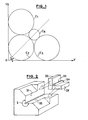
- Figure 1 will help to easily understand the geometric basis of centering an optical fiber in its tip.
- the system is extended to three dimensions, and the xOy axes are replaced by a right dihedral, the circles C1, C2 and C3 by three cylinders of the same diameter, and the circle C4 by an optical fiber, the latter is in the bisector plane of the dihedral, parallel to its intersection axis.
- the cyclinders In the case of an optical fiber, the diameter of which is commonly of the order of 125 microns, the cyclinders have a diameter of 302 microns, to within a few tenths of a micron. More generally, the ratio of the diameters of three circles C1, C2, C3, equal, and tangent to two perpendicular axes, and moreover tangent to a circle C4, is equal to 2.421.
- the precise dimension of the optical fiber, with respect to the reference faces of the centering device and the end piece is determined and obtained using two shims, to a constant K equal to the diameters of C1, C2, C3 close. These shims are related to the diameter of the end piece.
- FIG. 2 represents such a device according to the invention, in one of the possible embodiments.
- This device machined from a block of material. rigid such as for example a steel, has a single dihedral 2, generally hollow, and preferably straight - the precision obtained during machining is greater for a right angle rather than for any angle - allowing the coincidence between the reference faces of the tip and the reference faces 21 and 22 of the dihedral.
- the optical fiber centering assembly consists of two cylinders with identical diameters 23 & 24, and two orthogonal shims 25 & 26, of identical thicknesses. Referring to FIG. 1, it appears that the two cylinders 23 & 24 correspond to the circles C2 & C3, and that they form between them a housing in which the optical fiber will come to rest.
- the optical fiber is indeed in the bisector plane of the dihedral 2, when it is in its housing between 23 & 24.
- the centering assembly - the two shims and the two cylinders - is shown in exploded view in Figure 2 to facilitate understanding.
- this assembly is fixed, by any appropriate means, to the faces 21 and 22 of the dihedral, as symbolized in the figure by two arrows.
- the respective dimensions are such that the dihedron 2 can receive a tip and a centering assembly, both positioned with respect to the same reference dihedron: the tip and the optical fiber are thus perfectly aligned and marked, one with respect to to the other, or concentric if the end piece is of circular section.
- a tool such as the device described is fairly simple to produce since the only precision required relates to the flatness of the faces of the dihedron 2, the position and the angle of the dihedron not being involved in the precision of the connection.
- cyclinders and wedges are metrology parts, machined to the tenth of a micron, available from many suppliers.
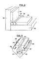
- FIG. 3 represents a detail of the device: one of the possible modes of fixing the cylinders 23 and 24 against the shims 25 and 26.
- the desired precision being of the order of a micron, bonding is excluded since it would introduce a layer " parasite "of glue several microns thick.
- the cylinders are therefore held in good position against the wedges 25 and 26 by means of two parts 31 and 32, bevelled on their face and which exert a force against the cylinders.
- the parts 31 and 32 can be welded or glued: their possible deformation would have no consequence, since these parts do not intervene directly in the centering of the optical fiber.
- a preferable solution consists in clamping all of these parts, against the dihedral 2, by means of two stirrups, the dimensions of which are sufficient for them to be screwed against the faces 21 and 22 of the dihedral.
- FIG. 4 represents a section, in cross section of the end of a nozzle used with the centering device according to the invention.
- the other end of the endpiece may include different means of protecting the optical fiber or de-fixing in a multiple connector for example, which are outside the scope of the invention.
- the end of the endpiece which belongs to the field of the invention is that which comes into contact with another endpiece to ensure the optical connection between two fibers. It is therefore the end in which the fiber must be positioned with the greatest precision.
- the tip is made of a rigid material, by machining, die-casting molding or any other suitable process. It is characterized by its two main planar faces 41 - and 42, forming a dihedral, generally projecting and preferably straight, but in all cases identical to the dihedron 2 of the centering device.
- a third main planar face 43 has a groove 44, parallel to the edge of the dihedral previously described, of a width greater than the diameter of the fiber and of a depth greater than the theoretical distance of the fiber from this face 43.
- a preferred form of groove consists of r widen it in the region where the fiber is located: the fiber can thus be inserted into the groove without touching the tip, which therefore allows its precise positioning.
- the optical fiber 45 is shown therein in dotted lines: after precise positioning of the fiber in the end piece, by means of the device according to the invention, the fiber is immobilized by means of a glue, introduced into the groove 44.
- This glue is preferably polymerizable and hardenable at ordinary temperature, and it is loaded with quartz or glass powder, in order to facilitate the subsequent polishing of the end of the endpiece.
- the shape and number of the other secondary faces of the nozzle do not play a determining role.
- the end piece also comprises, on two secondary faces, two grooves 46 and 47, the particularity of which is that each of them is located on a face opposite to a face of the dihedron.
- the groove 46 is cut in a face opposite to the face 42, with respect to the center of the optical fiber, and the groove 47 is cut in a face opposite to the face 41.
- These grooves receive elastic means, such as spring blades 48 and 49.
- the spring blades do not intervene during the centering of the fiber, in the device according to the invention: they intervene in the connector, grouping two ends, and ensure the centering of the optical fiber, by exerting a pressure which places the dihedral 41-42 in good position relative to to the connector housing.
- the fiber and the tip are both identified with respect to a single dihedron, the dihedron 2 of the figure 2.
- Figure 5 is related to the tool used and shows the device according to the invention in the case where the connector to be produced no longer has a single optical link, but the connection of two bundles of fibers.
- FIG. 5 represents the first four dihedrons of such a multiple tool: the calibrated cylinders 23 and 24 and the wedges 25 and 26 are shown, by way of illustration, in the first dihedron.
- FIG. 6 represents a type of monofiber tip produced with the means of the invention.
- the optical fiber appears in the center of the connection face, and is also shown, partially covered with its protective sheath, on the "line" side of the endpiece.
- the reference dihedral consists of the two planes 41 and 42, and elastic means, such as leaf springs 48 and 49, apply the end piece against another dihedral, of reference, identical to that defined by the planes 41 and 42, but which is part of the connector housing.
- Means are provided for holding the end piece in the connector housing and against another identical end piece with which it constitutes a connection: purely for explanatory purposes, these means are shown in the form of a thread.
Landscapes
- Physics & Mathematics (AREA)
- General Physics & Mathematics (AREA)
- Optics & Photonics (AREA)
- Mechanical Coupling Of Light Guides (AREA)
Applications Claiming Priority (2)
| Application Number | Priority Date | Filing Date | Title |
|---|---|---|---|
| FR7830849A FR2440562A1 (fr) | 1978-10-31 | 1978-10-31 | Dispositif de centrage d'une fibre optique dans un embout, et embout realise au moyen de ce dispositif |
| FR7830849 | 1978-10-31 |
Publications (2)
| Publication Number | Publication Date |
|---|---|
| EP0011012A1 true EP0011012A1 (de) | 1980-05-14 |
| EP0011012B1 EP0011012B1 (de) | 1983-06-08 |
Family
ID=9214329
Family Applications (1)
| Application Number | Title | Priority Date | Filing Date |
|---|---|---|---|
| EP79400758A Expired EP0011012B1 (de) | 1978-10-31 | 1979-10-17 | Zentriervorrichtung für eine optische Faser in einer Zwinge und Zwinge mit einer optischem Faser die mit dieser Vorrichtung zentriert worden ist |
Country Status (6)
| Country | Link |
|---|---|
| US (1) | US4296997A (de) |
| EP (1) | EP0011012B1 (de) |
| JP (1) | JPS5560908A (de) |
| CA (1) | CA1141212A (de) |
| DE (1) | DE2965627D1 (de) |
| FR (1) | FR2440562A1 (de) |
Cited By (1)
| Publication number | Priority date | Publication date | Assignee | Title |
|---|---|---|---|---|
| FR2487528A1 (fr) * | 1980-07-22 | 1982-01-29 | Noane Georges | Procede et appareil de montage d'embout de raccordement pour fibres optiques et connecteur comportant un tel embout |
Families Citing this family (7)
| Publication number | Priority date | Publication date | Assignee | Title |
|---|---|---|---|---|
| DE3203929A1 (de) * | 1982-02-05 | 1983-08-11 | Siemens AG, 1000 Berlin und 8000 München | Loesbare kupplung fuer lichtleiter |
| FR2534386A1 (fr) * | 1982-10-08 | 1984-04-13 | Socapex | Dispositif de montage de fibres optiques dans un embout |
| FR2547661B1 (fr) * | 1983-06-14 | 1986-10-24 | Telecommunications Sa | Procede et dispositif de raccordement d'une fibre optique avec un detecteur photosensible et le procede de mise en oeuvre |
| GB8805015D0 (en) * | 1988-03-02 | 1988-03-30 | British Telecomm | Optical fibre locating apparatus |
| JPH0746890Y2 (ja) * | 1989-05-10 | 1995-10-25 | 沖電気工業株式会社 | 光コネクタのエレメント調心治具 |
| IL97562A0 (en) * | 1991-03-15 | 1992-06-21 | Scitex Corp Ltd | Assembly of elongated elements,particularly a fibre optic head,and a method of making same |
| US5631989A (en) * | 1995-11-22 | 1997-05-20 | Lucent Technologies Inc. | Fiber and active optical device interconnection assembly |
Citations (2)
| Publication number | Priority date | Publication date | Assignee | Title |
|---|---|---|---|---|
| DE2456151A1 (de) * | 1974-11-27 | 1976-08-12 | Siemens Ag | Steckverbindung fuer optische glasfasern |
| FR2332546A1 (fr) * | 1975-11-20 | 1977-06-17 | Int Standard Electric Corp | Terminaisons et connecteurs de fibres optiques |
Family Cites Families (6)
| Publication number | Priority date | Publication date | Assignee | Title |
|---|---|---|---|---|
| GB1372874A (en) * | 1971-12-22 | 1974-11-06 | Plessey Co Ltd | Joining optical waveguides |
| US3999841A (en) * | 1974-08-19 | 1976-12-28 | Gte Laboratories Incorporated | Method for forming an optical fiber connector |
| US3938895A (en) * | 1974-08-19 | 1976-02-17 | Gte Laboratories Incorporated | Method for positioning an optical fiber |
| US4193664A (en) * | 1977-03-11 | 1980-03-18 | International Standard Electric Corporation | Optical fiber connector |
| FR2390745A2 (fr) * | 1977-05-13 | 1978-12-08 | Socapex | Connecteur pour monofibre optique |
| FR2394823A1 (fr) * | 1977-06-17 | 1979-01-12 | Noane Georges Le | Appareillage et procede de montage sur chantier et sur cables de transmission par fibres optiques de pieces permettant des raccordements interchangeables |
-
1978
- 1978-10-31 FR FR7830849A patent/FR2440562A1/fr active Granted
-
1979
- 1979-10-17 DE DE7979400758T patent/DE2965627D1/de not_active Expired
- 1979-10-17 EP EP79400758A patent/EP0011012B1/de not_active Expired
- 1979-10-23 JP JP13694279A patent/JPS5560908A/ja active Pending
- 1979-10-25 US US06/088,458 patent/US4296997A/en not_active Expired - Lifetime
- 1979-10-26 CA CA000338502A patent/CA1141212A/en not_active Expired
Patent Citations (2)
| Publication number | Priority date | Publication date | Assignee | Title |
|---|---|---|---|---|
| DE2456151A1 (de) * | 1974-11-27 | 1976-08-12 | Siemens Ag | Steckverbindung fuer optische glasfasern |
| FR2332546A1 (fr) * | 1975-11-20 | 1977-06-17 | Int Standard Electric Corp | Terminaisons et connecteurs de fibres optiques |
Cited By (1)
| Publication number | Priority date | Publication date | Assignee | Title |
|---|---|---|---|---|
| FR2487528A1 (fr) * | 1980-07-22 | 1982-01-29 | Noane Georges | Procede et appareil de montage d'embout de raccordement pour fibres optiques et connecteur comportant un tel embout |
Also Published As
| Publication number | Publication date |
|---|---|
| FR2440562B1 (de) | 1982-06-18 |
| US4296997A (en) | 1981-10-27 |
| CA1141212A (en) | 1983-02-15 |
| EP0011012B1 (de) | 1983-06-08 |
| JPS5560908A (en) | 1980-05-08 |
| FR2440562A1 (fr) | 1980-05-30 |
| DE2965627D1 (en) | 1983-07-14 |
Similar Documents
| Publication | Publication Date | Title |
|---|---|---|
| CA1131952A (fr) | Connecteur pour liaison a fibre optique | |
| EP0008987B1 (de) | Zentriervorrichtung und Verfahren zur Herstellung eines Steckverbinders für eine optische Faser | |
| JP5967722B2 (ja) | フェルール組立方法 | |
| CA1126552A (fr) | Procede de raccordement de fibres optiques disposees en nappe dans un cable, et dispositif de mise en oeuvre du procede | |
| US6782146B2 (en) | Multiple polarization combiner-splitter-isolator and method of manufacturing the same | |
| EP0000145B1 (de) | Verbindung für Lichtleitfasern und Verfahren zum Anschluss einer Lichtleitfaser an eine Verbindung | |
| FR2606166A1 (fr) | Support de fibres optiques et dispositif le comportant | |
| FR2765693A1 (fr) | Appareil et procede d'alignement passif de fibre optique | |
| CA1087007A (fr) | Connecteur pour liaison a fibre optique | |
| EP0011012B1 (de) | Zentriervorrichtung für eine optische Faser in einer Zwinge und Zwinge mit einer optischem Faser die mit dieser Vorrichtung zentriert worden ist | |
| CH622357A5 (de) | ||
| FR2694419A1 (fr) | Procédé de couplage d'une fibre optique à un composant sur un substrat commun. | |
| EP0121460B1 (de) | Aufnahmestück für optische Fasern für eine Kupplungsvorrichtung und Verfahren zur Herstellung einer solchen Vorrichtung | |
| EP0520902B1 (de) | Vorrichtung mit transversal-anisotroper optischer Faser und Verfahren für ihre Herstellung | |
| US20040114865A1 (en) | Optical devices and methods | |
| EP0036369B1 (de) | Verfahren und Vorrichtung zum Verbinden faseroptischer Kabel auf dem Arbeitsplatz | |
| EP1525502B1 (de) | Verfahren und vorrichtung zum positionieren einer optischen komponente zwischen zwei optischen fasern | |
| CA2063208C (fr) | Procede de raccordement de deux cables a fibres optiques par epissurage | |
| EP0462881B1 (de) | Wand zur Abtrennung zweier Bereiche mit einer Vorrichtung zur Verbindung von zwei optischen Fasern | |
| FR2535069A1 (fr) | Embout de connexion optique multi-fibres, connecteur utilisant un tel embout et appareil pour le montage de fibres dans ledit embout | |
| CH642755A5 (en) | Ferrule for a device for connecting the ends of two optical fibres, and connection device comprising such a ferrule | |
| CN110709742A (zh) | 带透镜的光纤的制造方法、以及切断装置 | |
| FR2547425A1 (fr) | Procede et dispositif de centrage relatif d'une fibre optique et d'une lentille dans un embout, et element de connecteur ainsi obtenu | |
| EP0806688B1 (de) | Zentrierelement, Verfahren für die Verbindung einer Anzahl von Fasern an eine Mehrkernfaser und so hergestellte Koppel-/Verteilervorrichtung | |
| FR3071327B1 (fr) | Procede et systeme d'alignement de l'axe optique d'un cable optique avec un composant optoelectronique |
Legal Events
| Date | Code | Title | Description |
|---|---|---|---|
| PUAI | Public reference made under article 153(3) epc to a published international application that has entered the european phase |
Free format text: ORIGINAL CODE: 0009012 |
|
| AK | Designated contracting states |
Designated state(s): BE DE GB IT NL SE |
|
| 17P | Request for examination filed | ||
| ITF | It: translation for a ep patent filed | ||
| GRAA | (expected) grant |
Free format text: ORIGINAL CODE: 0009210 |
|
| AK | Designated contracting states |
Designated state(s): DE GB IT |
|
| REF | Corresponds to: |
Ref document number: 2965627 Country of ref document: DE Date of ref document: 19830714 |
|
| PLBE | No opposition filed within time limit |
Free format text: ORIGINAL CODE: 0009261 |
|
| STAA | Information on the status of an ep patent application or granted ep patent |
Free format text: STATUS: NO OPPOSITION FILED WITHIN TIME LIMIT |
|
| 26N | No opposition filed | ||
| PGFP | Annual fee paid to national office [announced via postgrant information from national office to epo] |
Ref country code: DE Payment date: 19891025 Year of fee payment: 11 |
|
| PGFP | Annual fee paid to national office [announced via postgrant information from national office to epo] |
Ref country code: GB Payment date: 19891031 Year of fee payment: 11 |
|
| PG25 | Lapsed in a contracting state [announced via postgrant information from national office to epo] |
Ref country code: GB Effective date: 19901017 |
|
| GBPC | Gb: european patent ceased through non-payment of renewal fee | ||
| PG25 | Lapsed in a contracting state [announced via postgrant information from national office to epo] |
Ref country code: DE Effective date: 19910702 |