EP0012332A1 - Fassungsstein für eine Glüh-Lampenfassung - Google Patents
Fassungsstein für eine Glüh-Lampenfassung Download PDFInfo
- Publication number
- EP0012332A1 EP0012332A1 EP79104909A EP79104909A EP0012332A1 EP 0012332 A1 EP0012332 A1 EP 0012332A1 EP 79104909 A EP79104909 A EP 79104909A EP 79104909 A EP79104909 A EP 79104909A EP 0012332 A1 EP0012332 A1 EP 0012332A1
- Authority
- EP
- European Patent Office
- Prior art keywords
- socket
- sleeve section
- sleeve
- contact tongue
- forming
- Prior art date
- Legal status (The legal status is an assumption and is not a legal conclusion. Google has not performed a legal analysis and makes no representation as to the accuracy of the status listed.)
- Granted
Links
- 239000011810 insulating material Substances 0.000 claims abstract description 4
- 239000011324 bead Substances 0.000 claims description 3
- 230000037431 insertion Effects 0.000 abstract description 5
- 238000003780 insertion Methods 0.000 abstract description 5
- 210000002105 tongue Anatomy 0.000 description 14
- 239000004575 stone Substances 0.000 description 8
- 241000209035 Ilex Species 0.000 description 4
- 239000002184 metal Substances 0.000 description 4
- 239000004020 conductor Substances 0.000 description 2
- 238000004519 manufacturing process Methods 0.000 description 2
- 238000002788 crimping Methods 0.000 description 1
- 238000009434 installation Methods 0.000 description 1
- 239000012778 molding material Substances 0.000 description 1
Images


Classifications
-
- H—ELECTRICITY
- H01—ELECTRIC ELEMENTS
- H01R—ELECTRICALLY-CONDUCTIVE CONNECTIONS; STRUCTURAL ASSOCIATIONS OF A PLURALITY OF MUTUALLY-INSULATED ELECTRICAL CONNECTING ELEMENTS; COUPLING DEVICES; CURRENT COLLECTORS
- H01R33/00—Coupling devices specially adapted for supporting apparatus and having one part acting as a holder providing support and electrical connection via a counterpart which is structurally associated with the apparatus, e.g. lamp holders; Separate parts thereof
- H01R33/05—Two-pole devices
- H01R33/22—Two-pole devices for screw type base, e.g. for lamp
Definitions
- the invention relates to a socket for an incandescent lamp socket made of insulating material for receiving a sleeve section forming a hollow rivet, which is used to hold a contact tongue forming a socket contact, with a further squeezable sleeve section for receiving one of the two lead wires, the sleeve section forming the hollow rivet holds the contact tongue with a tight fit in the socket.
- a frame stone of this type is known from DE-Gbm 7 811 012.
- the sleeve section which forms a hollow rivet for fastening a contact tongue of the socket contact, is used to receive a pin, which has at its outer end a connecting lug which can grip the strand of a connecting line by means of a crimp connection, so that a first for the mounting of the socket stone Inserting the hollow rivet into the socket and then inserting the pin into the hollow rivet is required in order to complete the connection of a strand with a crimp connection.
- the invention has for its object to form a socket of the type mentioned in such a way that its manufacture is cheaper and the assembly time required for connecting the strands or wires can be shortened, the supply and holding arrangement of the contact being able to be produced from only two components.
- the sleeve section forming the hollow rivet expediently consists of a turned rivet sleeve which has two axially spaced shoulders, one of which rests on the socket, while the other serves as a stop for the contact tongue.
- the sleeve section forming the hollow rivet can also consist of a drawn sleeve which has two beads which are different in diameter and are axially spaced apart, one of which rests on the socket while the other serves as a stop for the contact tongue.
- verquetschbare sleeve portion and the contact tongue are produced in one piece from a stamped profile which is held by a hollow rivet in the lampholder interior, and an elongated Kunststoffzun g en Scheme having at its end an opening for receiving the Hollow rivets lie, and which is followed by a further elongated area with a zigzag or wavy side edge.
- the contact tongue area and the zigzag-shaped area are advantageously at right angles to one another.
- the manufacture of the socket is cheaper because the previously required pin for connecting the squeezable sleeve portion and the sleeve portion forming a rivet is eliminated. Furthermore, the assembly time is shortened because only a single insert is required for the assembly of the socket stone operation is required, namely the insertion of the hollow rivet section into the socket, while the insertion of a pin into this hollow rivet section is omitted.
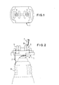
- the socket 1 shown in FIGS. 1 to 3 has, as a clamping body for the connecting wires 7, of which only one is shown, sleeves 5, into each of which a stripped end 8 of a connecting wire 7 is inserted, whereupon the sleeves in their upper section a tool known per se can be crushed.
- the lower part of the sleeve which, as can be seen from FIG. 3, has a larger outer diameter than the area of the sleeve intended for squeezing, is fixed. connected to a contact tongue 2 or 3, which is done in a known manner by flanging the lower edge of the sleeve.
- the contact tongues 2 and 3 are used to establish contact with the lamp base 9 indicated by dashed lines.
- the sleeves 5 are each arranged between two ribs of the insulating part, so that there is sufficient space in the longitudinal direction of the ribs for gripping a pair of crimping pliers.
- the rotated sleeve shown in this figure has two shoulders 10 and 11 in its hollow rivet section 5b, of which the shoulder 10 lies against the setting stone 1, while the shoulder 11 serves as a support for the by flanging connecting center contact 3 (or side contact 2) is used.
- the shoulder 10 lies against the setting stone 1
- the shoulder 11 serves as a support for the by flanging connecting center contact 3 (or side contact 2) is used.
- FIG. 3 represents a turned rivet
- FIG. 5 shows a sheet metal blank of a further embodiment of a pinchable sleeve 5 "in which the sleeve 5" is made in one piece with a contact tongue 3
- the part of the sheet metal blank cut out at an angle of 90 is first bent inwards in a circle and then squeezed with the conductor after insertion, as can best be seen from FIG. 8, according to which the sleeve 5a "is formed by means of a Sleeve 14 is riveted in the socket.
- Fig. 6 The shape of the combination arrangement of squeezable sleeve 5a "and contact tongue 3" before insertion into the socket is shown in Fig. 6, in which the tongues 15 formed by the stamped profile for embracing the conductor are in an opposing position before being squeezed.
- the stamped profile has an elongated contact tongue 3 ′′, at the end of which there is an opening 16 for receiving the hollow rivet 14, and which is followed by a further elongated area with a zigzag-shaped or wavy side edge.
- the contact tongue area and the zigzag-shaped area are at right angles to one another.
Landscapes
- Fastening Of Light Sources Or Lamp Holders (AREA)
- Ceramic Products (AREA)
- Connecting Device With Holders (AREA)
Abstract
Description
- Die Erfindung bezieht sich auf einen Fassungsstein für eine Glüh-Lampenfassung aus Isolierstoff zur Aufnahme eines einen Hohlniet bildenden Hülsenabschnittes, der zur Halterung einer einen Fassungskontakt bildenden Kontaktzunge dient, mit einem weiteren verquetschbaren Hülsenabschnitt zur Aufnahme eines der beiden Leitungsdrähte, wobei der den Hohlniet bildende Hülsenabschnitt mit einem Festsitz im Fassungsstein jeweils die Kontaktzunge hält.
- Ein Fassungsstein dieser Art ist aus dem DE-Gbm 7 811 012 bekannt. Bei der bekannten Anordnung dient der ein Hohlniet zur Befestigung einer Kontaktzunge des Fassungskontakts bildende Hülsenabschnitt zur Aufnahme eines Stifts, der an seinem äußeren Ende eine Anschlußfahne besitzt, die mittels einer Quetschverbindung die Litze einer Anschlußleitung ergreifen kann, so daß für die Montage des Fassungssteins zuerst ein Einsetzen des Hohlniets in den Fassungsstein und anschließend ein Einstecken des Stifts in den Hohlniet erforderlich ist, um mit erfolgter Quetschverbindung den Anschluß einer Litze fertigzustellen.
- Der Erfindung liegt die Aufgabe zugrunde, einen Fassungsstein der eingangs genannten Art derart auszubilden, daß seine Herstellung verbilligt und die für den Anschluß der Litzen oder Drähte erforderliche Montagezeit verkürzt werden kann, wobei Zuleitungs- und Halteanordnung des Kontakts aus nur zwei Bauteilen herstellbar sind.
- Diese Aufgabe wird bei einem Fassungsstein der eingangs beschriebenen Art erfindungsgemäß dadurch gelöst, daß die beiden Hülsenabschnitte einstückig miteinander ausgebildet sind und unter Anordnung einer Schulter zwischen dem einen relativ größeren Durchmesser aufweisenden, den Hohlniet bildenden Hülsenabschnitt und dem einen relativ kleineren Durchmesser aufweisenden verquetschbaren Hülsenabschnitt ineinander übergehen.
- Zweckmäßig besteht der den Hohlniet bildende Hülsenabschnitt aus einer gedrehten Niethülse, die zwei im axialen Abstand liegende Schultern aufweist, wovon die eine am Fassungsstein anliegt, während die andere als Anschlag für die Kontaktzunge dient.
- Der den Hohlniet bildende Hülsenabschnitt kann auch aus einer gezogenen Hülse bestehen, die zwei im Durchmesser unterschiedliche, im axialen Abstand voneinander liegende Wülste aufweist, wovon der eine am Fassungsstein anliegt, während der andere als Anschlag für die Kontaktzunge dient.
- Eine alternative Lösung der Aufgabe der Erfindung besteht darin, daß der verquetschbare Hülsenabschnitt und die Kontaktzunge einstückig aus einem Stanzprofil hergestellt sind, das von einem Hohlniet im Fassungsstein gehalten wird, und das einen länglichen Kontaktzungenbereich aufweist, an dessen Ende eine Öffnung zur Aufnahme des Hohlniets liegt, und an den sich ein weiterer länglicher Bereich mit zick-zack-förmiger oder wellenförmiger Seitenkante anschließt.
- Vorteilhaft liegen dabei der Kontaktzungenbereich und der zick=zack-förmige Bereich im rechten Winkel zueinander.
- Als Folge der Erfindung wird die Herstellung des Fassungssteins verbilligt, weil der bisher benötigte Anschlußstift zur Verbindung des verquetschbaren Hülsenabschnittes und des einen Hohlniet bildenden Hülsenabschnittes entfällt. Ferner wird die Montagezeit verkürzt, weil für die Montage des Fassungssteins nur ein einziger Einsteckvorgang erforderlich ist, nämlich das Einstecken des Hohlnietabschnittes in den Fassungsstein, während das Einstekken eines Stifts in diesen Hohlnietabschnitt entfällt.
- Die Erfindung ist im folgenden anhand von in den Zeichnungen dargestellten Ausführungsbeispielen näher erläutert. In den Zeichnungen zeigen:
- Fig. 1 eine Draufsicht auf einen Fassungsstein gemäß der Erfindung,
- Fig. 2 eine Seitenansicht des Fassungssteines nach Fig. 1,
- Fig. 3 eine Einzelansicht der beim erfindungsgemäßen Fassungsstein verwendeten Hülse,
- Fig. 4 einen Querschnitt durch eine andere Ausführungsform der beim erfindungsgemäßen Fassungsstein verwendeten Hülse,
- Fig. 5 einen Blechzuschnitt, der sich zur Herstellung einer weiteren Ausführungsform einer beim erfindungsgemäßen Fassungsstein verwendeten verquetschbaren Hülse eignet,
- Fig. 6 eine aus dem Blechzuschnitt nach Fig. 5 erhaltene Hülsenanordnung,
- Fig. -7 eine Draufsicht auf die Unterseite eines Fassungssteins mit eingebauter Hülsenanordnung gemäß Fig. 6, und
- Fig. 8 einen Schnitt gemäß der Linie 8-8 durch die Anordnung der Fig. 7, durch welchen der Einbau der in Fig. 6 dargestellten verquetschbaren Hülse verdeutlicht wird.
- Der in den Fig. 1 bis 3 dargestellte Fassungsstein 1 besitzt als Klemmkörper für die Anschlußdrähte 7, von denen nur einer dargestellt ist, Hülsen 5, in welche jeweils ein abisoliertes Ende 8 eines Anschlußdrahtes 7 eingesteckt wird, worauf die Hülsen in ihrem oberen Abschnitt durch ein an sich bekanntes Werkzeug verquetscht werden. Der untere Teil der Hülse, der, wie aus Fig. 3 ersichtlich ist, einen größeren Außendurchmesser als der zum Verquetschen bestimmte Bereich der Hülse aufweist, ist fest . mit einer Kontaktzunge 2 bzw. 3 verbunden, was in bekannter Weise durch Umbördelung des unteren Hülsenrandes erfolgt. Die Kontaktzungen 2 bzw 3 dienen zur Herstellung des Kontaktes mit dem gestrichelt angedeuteten Lampensokkel 9.
- Die Hülsen 5 sind jeweils zwischen zwei Rippen des Isolierstoffteiles angeordnet, so daß in Längsrichtung der Rippen genügend Raum zum Angreifen einer Quetschzange vorhanden ist.
- Aus Fig. 3 ist ersichtlich, daß der zum Verquetschen bestimmte Bereich 5a der Hülse gegenüber dem im Fassungsstein einzusetzenden Bereich 5b einen erheblich verringerten Durchmesser aufweist.
- Wie aus Fig. 3 ersichtlich ist, weist die in dieser.Figur dargestellte gedrehte Hülse in ihrem Hohlnietabschnitt 5b zwei Schultern 10 und 11 auf, wovon sich die Schulter 10 gegen den Fassungsstein 1 legt, während die Schulter 11 als Auflage für den durch Bördelung zu verbindenden Mittelkontakt 3 (bzw. Seitenkontakt 2) dient. Auf diese Weise wird erreicht, daß bei einer etwaigen Schrumpfung des Isolierpreßstoffes des Fassungssteins immer eine gute elektrische Verbindung zwischen den Kontakten und dem Hohlniet bestehen bleibt.
- Während die Anordnung der Fig. 3 einen gedrehten Hohlniet darstellt, kann statt dessen auch gemäß Fig. 4 eine gezogene Bundhülse 5' verwendet werden, die zwei im Durchmesser unterschiedliche Wulste 12 und 13 als Anschläge aufweist, welche die gleiche Funktion, wie die in Fig. 3 dargestellten Schultern 10 und 11 haben.
- Die erfindungsgemäße Vereinfachung läßt sich auch erreichen, ohne daß der verquetschbare Hülsenabschnitt als Rotationskörper ausgebildet ist, wie dies aus Fig. 5 hervorgeht, die einen Blechzuschnitt einer weiteren Ausführungsform einer verquetschbaren Hülse 5" zeigt, bei der die Hülse 5" einstückig mit einer Kontaktzunge 3" ausgeführt ist. Der jeweils unter dem Winkel von 90 ausgeschnittene Teil des Blechzuschnittes wird zunächst kreisförmig nach innen gebogen und dann nach Einfügung des Leiters mit diesem verquetscht, wie dies am besten aus Fig. 8 ersichtlich ist, gemäß welcher die Hülse 5a" mittels einer Hülse 14 im Fassungsstein vernietet wird.
- Die Formgebung der Kombinationsanordnung aus verquetschbarer Hülse 5a" und Kontaktzunge 3" vor dem Einsetzen in den Fassungsstein ist in Fig. 6 dargestellt, in der sich die durch das Stanzprofil gebildeten Zungen 15 zum Umfassen des Leiters in einander gegenüberliegender Lage vor dem Verquetschen befinden.
- Das Stanzprofil weist eine längliche Kontaktzunge 3" auf, an deren Ende eine Öffnung 16 zur Aufnahme des Hohlniets 14 liegt, und an die sich ein weiterer länglicher Bereich mit zick-zack-förmiger oder wellenförmiger Seitenkante anschließt.
- Der Kontaktzungenbereich und der zick-zack-förmige Bereich liegen im rechten Winkel zueinander.
Claims (5)
Priority Applications (1)
| Application Number | Priority Date | Filing Date | Title |
|---|---|---|---|
| AT79104909T ATE3230T1 (de) | 1978-12-06 | 1979-12-04 | Fassungsstein fuer eine glueh-lampenfassung. |
Applications Claiming Priority (2)
| Application Number | Priority Date | Filing Date | Title |
|---|---|---|---|
| DE7836219U DE7836219U1 (de) | 1978-12-06 | 1978-12-06 | Fassungsstein für eine Glfih-Lampen- |
| DE7836219U | 1978-12-06 |
Publications (2)
| Publication Number | Publication Date |
|---|---|
| EP0012332A1 true EP0012332A1 (de) | 1980-06-25 |
| EP0012332B1 EP0012332B1 (de) | 1983-05-04 |
Family
ID=6697634
Family Applications (1)
| Application Number | Title | Priority Date | Filing Date |
|---|---|---|---|
| EP79104909A Expired EP0012332B1 (de) | 1978-12-06 | 1979-12-04 | Fassungsstein für eine Glüh-Lampenfassung |
Country Status (3)
| Country | Link |
|---|---|
| EP (1) | EP0012332B1 (de) |
| AT (1) | ATE3230T1 (de) |
| DE (2) | DE7836219U1 (de) |
Citations (5)
| Publication number | Priority date | Publication date | Assignee | Title |
|---|---|---|---|---|
| US1955285A (en) * | 1931-04-18 | 1934-04-17 | Electric Service Supplies Co | Electrical receptacle |
| US2557337A (en) * | 1947-10-24 | 1951-06-19 | American Molded Products Co | Lamp socket construction |
| FR1492998A (fr) * | 1966-07-11 | 1967-08-25 | Cibie Projecteurs | Perfectionnements aux ensembles porte-lampes |
| DE7235210U (de) * | 1972-09-25 | 1976-11-11 | Siemens Ag, 1000 Berlin Und 8000 Muenchen | Fassung, vorzugsweise Lampenfassung für die Lichtsignalgeber von Straßenverkehrs-Signalanlagen |
| DE7811012U1 (de) * | 1978-04-13 | 1978-07-27 | Lindner Gmbh, Fabrik Elektrischer Lampen Und Apparate, 8600 Bamberg | Elektrische Lampenfassung mit schraubenlosen Leitungsanschlußkontakten |
-
1978
- 1978-12-06 DE DE7836219U patent/DE7836219U1/de not_active Expired
-
1979
- 1979-12-04 AT AT79104909T patent/ATE3230T1/de not_active IP Right Cessation
- 1979-12-04 DE DE7979104909T patent/DE2965327D1/de not_active Expired
- 1979-12-04 EP EP79104909A patent/EP0012332B1/de not_active Expired
Patent Citations (5)
| Publication number | Priority date | Publication date | Assignee | Title |
|---|---|---|---|---|
| US1955285A (en) * | 1931-04-18 | 1934-04-17 | Electric Service Supplies Co | Electrical receptacle |
| US2557337A (en) * | 1947-10-24 | 1951-06-19 | American Molded Products Co | Lamp socket construction |
| FR1492998A (fr) * | 1966-07-11 | 1967-08-25 | Cibie Projecteurs | Perfectionnements aux ensembles porte-lampes |
| DE7235210U (de) * | 1972-09-25 | 1976-11-11 | Siemens Ag, 1000 Berlin Und 8000 Muenchen | Fassung, vorzugsweise Lampenfassung für die Lichtsignalgeber von Straßenverkehrs-Signalanlagen |
| DE7811012U1 (de) * | 1978-04-13 | 1978-07-27 | Lindner Gmbh, Fabrik Elektrischer Lampen Und Apparate, 8600 Bamberg | Elektrische Lampenfassung mit schraubenlosen Leitungsanschlußkontakten |
Also Published As
| Publication number | Publication date |
|---|---|
| DE7836219U1 (de) | 1979-04-05 |
| EP0012332B1 (de) | 1983-05-04 |
| ATE3230T1 (de) | 1983-05-15 |
| DE2965327D1 (en) | 1983-06-09 |
Similar Documents
| Publication | Publication Date | Title |
|---|---|---|
| DE69013582T2 (de) | Keilförmiger Sockel, befestigt an SPG-Substrat. | |
| DE10239273A1 (de) | Federkraftklemmanschluß für einen elektrischen Leiter | |
| DE2414640B2 (de) | Elektrischer Verbinder mit einer metallischen Anschlußklemme | |
| EP0371300A2 (de) | Sonnenblende für Fahrzeuge | |
| DE69109368T2 (de) | Sicherungseinheit, insbesondere für gedruckte Schaltung. | |
| DE4111054C2 (de) | ||
| DD269496A5 (de) | Schneidklemm-huelsenkontakt | |
| DE3912189A1 (de) | Schutzleiterverbindung | |
| DE1151578B (de) | Loetfreier Verbinder | |
| DE2941011C2 (de) | ||
| DE69103593T2 (de) | Schnellkupplungseinrichtung für Batterieendklemme. | |
| EP1255273A2 (de) | Elektrische Lampe | |
| EP0319633B1 (de) | Cinch-Stecker | |
| DE2013542A1 (de) | ||
| EP0854497A2 (de) | Kompakte Niederdruckentladungslampe | |
| EP0167911B1 (de) | Elektrokochplatte | |
| EP0012332A1 (de) | Fassungsstein für eine Glüh-Lampenfassung | |
| DE2612490A1 (de) | Elektrische mehrfachsteckdose | |
| DE69509431T2 (de) | Antennenfuss mit einer Mutter, die von einer Basis gehalten wird, die nur eine Montagerichtung erlaubt | |
| DE60021990T2 (de) | Elektrische lampe | |
| DE970575C (de) | Fassung fuer Leuchtroehren | |
| DE2018702B2 (de) | Elektrische Lampe mit einem Lampensockel aus Kunststoff | |
| DE936524C (de) | Federnder Kontakt zur Aufnahme von Steckerstiften | |
| DE8514801U1 (de) | Elektrische Kontaktvorrichtung | |
| DE10000618C1 (de) | Steckkontakt |
Legal Events
| Date | Code | Title | Description |
|---|---|---|---|
| PUAI | Public reference made under article 153(3) epc to a published international application that has entered the european phase |
Free format text: ORIGINAL CODE: 0009012 |
|
| AK | Designated contracting states |
Designated state(s): AT BE CH DE FR GB IT LU NL SE |
|
| 17P | Request for examination filed | ||
| ITF | It: translation for a ep patent filed | ||
| GRAA | (expected) grant |
Free format text: ORIGINAL CODE: 0009210 |
|
| AK | Designated contracting states |
Designated state(s): AT BE CH DE FR GB IT LU NL SE |
|
| REF | Corresponds to: |
Ref document number: 3230 Country of ref document: AT Date of ref document: 19830515 Kind code of ref document: T |
|
| ET | Fr: translation filed | ||
| REF | Corresponds to: |
Ref document number: 2965327 Country of ref document: DE Date of ref document: 19830609 |
|
| PGFP | Annual fee paid to national office [announced via postgrant information from national office to epo] |
Ref country code: AT Payment date: 19831207 Year of fee payment: 5 |
|
| PGFP | Annual fee paid to national office [announced via postgrant information from national office to epo] |
Ref country code: FR Payment date: 19831227 Year of fee payment: 5 |
|
| PG25 | Lapsed in a contracting state [announced via postgrant information from national office to epo] |
Ref country code: LU Free format text: LAPSE BECAUSE OF NON-PAYMENT OF DUE FEES Effective date: 19831231 |
|
| PGFP | Annual fee paid to national office [announced via postgrant information from national office to epo] |
Ref country code: SE Payment date: 19831231 Year of fee payment: 5 Ref country code: NL Payment date: 19831231 Year of fee payment: 5 Ref country code: BE Payment date: 19831231 Year of fee payment: 5 |
|
| PGFP | Annual fee paid to national office [announced via postgrant information from national office to epo] |
Ref country code: DE Payment date: 19840119 Year of fee payment: 5 |
|
| PGFP | Annual fee paid to national office [announced via postgrant information from national office to epo] |
Ref country code: CH Payment date: 19840125 Year of fee payment: 5 |
|
| PLBE | No opposition filed within time limit |
Free format text: ORIGINAL CODE: 0009261 |
|
| STAA | Information on the status of an ep patent application or granted ep patent |
Free format text: STATUS: NO OPPOSITION FILED WITHIN TIME LIMIT |
|
| 26N | No opposition filed | ||
| PG25 | Lapsed in a contracting state [announced via postgrant information from national office to epo] |
Ref country code: AT Effective date: 19841204 |
|
| PG25 | Lapsed in a contracting state [announced via postgrant information from national office to epo] |
Ref country code: SE Effective date: 19841205 |
|
| PG25 | Lapsed in a contracting state [announced via postgrant information from national office to epo] |
Ref country code: CH Effective date: 19841231 Ref country code: BE Effective date: 19841231 |
|
| BERE | Be: lapsed |
Owner name: VOSSLOH-WERKE G.M.B.H. Effective date: 19841204 |
|
| PG25 | Lapsed in a contracting state [announced via postgrant information from national office to epo] |
Ref country code: NL Effective date: 19850701 |
|
| GBPC | Gb: european patent ceased through non-payment of renewal fee | ||
| NLV4 | Nl: lapsed or anulled due to non-payment of the annual fee | ||
| PG25 | Lapsed in a contracting state [announced via postgrant information from national office to epo] |
Ref country code: FR Free format text: LAPSE BECAUSE OF NON-PAYMENT OF DUE FEES Effective date: 19850830 |
|
| REG | Reference to a national code |
Ref country code: CH Ref legal event code: PL |
|
| PG25 | Lapsed in a contracting state [announced via postgrant information from national office to epo] |
Ref country code: DE Effective date: 19850903 |
|
| REG | Reference to a national code |
Ref country code: FR Ref legal event code: ST |
|
| PG25 | Lapsed in a contracting state [announced via postgrant information from national office to epo] |
Ref country code: GB Effective date: 19881118 |
|
| EUG | Se: european patent has lapsed |
Ref document number: 79104909.1 Effective date: 19851008 |