EP0013251B1 - Emballage fermé, à usage unique - Google Patents
Emballage fermé, à usage unique Download PDFInfo
- Publication number
- EP0013251B1 EP0013251B1 EP19790420070 EP79420070A EP0013251B1 EP 0013251 B1 EP0013251 B1 EP 0013251B1 EP 19790420070 EP19790420070 EP 19790420070 EP 79420070 A EP79420070 A EP 79420070A EP 0013251 B1 EP0013251 B1 EP 0013251B1
- Authority
- EP
- European Patent Office
- Prior art keywords
- sheet
- consumable product
- cartridge
- coating
- mild steel
- Prior art date
- Legal status (The legal status is an assumption and is not a legal conclusion. Google has not performed a legal analysis and makes no representation as to the accuracy of the status listed.)
- Expired
Links
Images
Classifications
-
- B—PERFORMING OPERATIONS; TRANSPORTING
- B65—CONVEYING; PACKING; STORING; HANDLING THIN OR FILAMENTARY MATERIAL
- B65D—CONTAINERS FOR STORAGE OR TRANSPORT OF ARTICLES OR MATERIALS, e.g. BAGS, BARRELS, BOTTLES, BOXES, CANS, CARTONS, CRATES, DRUMS, JARS, TANKS, HOPPERS, FORWARDING CONTAINERS; ACCESSORIES, CLOSURES, OR FITTINGS THEREFOR; PACKAGING ELEMENTS; PACKAGES
- B65D25/00—Details of other kinds or types of rigid or semi-rigid containers
- B65D25/34—Coverings or external coatings
-
- B—PERFORMING OPERATIONS; TRANSPORTING
- B21—MECHANICAL METAL-WORKING WITHOUT ESSENTIALLY REMOVING MATERIAL; PUNCHING METAL
- B21D—WORKING OR PROCESSING OF SHEET METAL OR METAL TUBES, RODS OR PROFILES WITHOUT ESSENTIALLY REMOVING MATERIAL; PUNCHING METAL
- B21D22/00—Shaping without cutting, by stamping, spinning, or deep-drawing
- B21D22/20—Deep-drawing
- B21D22/201—Work-pieces; preparation of the work-pieces, e.g. lubricating, coating
-
- F—MECHANICAL ENGINEERING; LIGHTING; HEATING; WEAPONS; BLASTING
- F17—STORING OR DISTRIBUTING GASES OR LIQUIDS
- F17C—VESSELS FOR CONTAINING OR STORING COMPRESSED, LIQUEFIED OR SOLIDIFIED GASES; FIXED-CAPACITY GAS-HOLDERS; FILLING VESSELS WITH, OR DISCHARGING FROM VESSELS, COMPRESSED, LIQUEFIED, OR SOLIDIFIED GASES
- F17C1/00—Pressure vessels, e.g. gas cylinder, gas tank, replaceable cartridge
- F17C1/10—Pressure vessels, e.g. gas cylinder, gas tank, replaceable cartridge with provision for protection against corrosion, e.g. due to gaseous acid
-
- F—MECHANICAL ENGINEERING; LIGHTING; HEATING; WEAPONS; BLASTING
- F17—STORING OR DISTRIBUTING GASES OR LIQUIDS
- F17C—VESSELS FOR CONTAINING OR STORING COMPRESSED, LIQUEFIED OR SOLIDIFIED GASES; FIXED-CAPACITY GAS-HOLDERS; FILLING VESSELS WITH, OR DISCHARGING FROM VESSELS, COMPRESSED, LIQUEFIED, OR SOLIDIFIED GASES
- F17C2201/00—Vessel construction, in particular geometry, arrangement or size
- F17C2201/01—Shape
- F17C2201/0104—Shape cylindrical
- F17C2201/0109—Shape cylindrical with exteriorly curved end-piece
-
- F—MECHANICAL ENGINEERING; LIGHTING; HEATING; WEAPONS; BLASTING
- F17—STORING OR DISTRIBUTING GASES OR LIQUIDS
- F17C—VESSELS FOR CONTAINING OR STORING COMPRESSED, LIQUEFIED OR SOLIDIFIED GASES; FIXED-CAPACITY GAS-HOLDERS; FILLING VESSELS WITH, OR DISCHARGING FROM VESSELS, COMPRESSED, LIQUEFIED, OR SOLIDIFIED GASES
- F17C2201/00—Vessel construction, in particular geometry, arrangement or size
- F17C2201/01—Shape
- F17C2201/0104—Shape cylindrical
- F17C2201/0119—Shape cylindrical with flat end-piece
-
- F—MECHANICAL ENGINEERING; LIGHTING; HEATING; WEAPONS; BLASTING
- F17—STORING OR DISTRIBUTING GASES OR LIQUIDS
- F17C—VESSELS FOR CONTAINING OR STORING COMPRESSED, LIQUEFIED OR SOLIDIFIED GASES; FIXED-CAPACITY GAS-HOLDERS; FILLING VESSELS WITH, OR DISCHARGING FROM VESSELS, COMPRESSED, LIQUEFIED, OR SOLIDIFIED GASES
- F17C2201/00—Vessel construction, in particular geometry, arrangement or size
- F17C2201/03—Orientation
- F17C2201/032—Orientation with substantially vertical main axis
-
- F—MECHANICAL ENGINEERING; LIGHTING; HEATING; WEAPONS; BLASTING
- F17—STORING OR DISTRIBUTING GASES OR LIQUIDS
- F17C—VESSELS FOR CONTAINING OR STORING COMPRESSED, LIQUEFIED OR SOLIDIFIED GASES; FIXED-CAPACITY GAS-HOLDERS; FILLING VESSELS WITH, OR DISCHARGING FROM VESSELS, COMPRESSED, LIQUEFIED, OR SOLIDIFIED GASES
- F17C2203/00—Vessel construction, in particular walls or details thereof
- F17C2203/06—Materials for walls or layers thereof; Properties or structures of walls or their materials
- F17C2203/0602—Wall structures; Special features thereof
- F17C2203/0607—Coatings
-
- F—MECHANICAL ENGINEERING; LIGHTING; HEATING; WEAPONS; BLASTING
- F17—STORING OR DISTRIBUTING GASES OR LIQUIDS
- F17C—VESSELS FOR CONTAINING OR STORING COMPRESSED, LIQUEFIED OR SOLIDIFIED GASES; FIXED-CAPACITY GAS-HOLDERS; FILLING VESSELS WITH, OR DISCHARGING FROM VESSELS, COMPRESSED, LIQUEFIED, OR SOLIDIFIED GASES
- F17C2203/00—Vessel construction, in particular walls or details thereof
- F17C2203/06—Materials for walls or layers thereof; Properties or structures of walls or their materials
- F17C2203/0602—Wall structures; Special features thereof
- F17C2203/0612—Wall structures
- F17C2203/0614—Single wall
- F17C2203/0624—Single wall with four or more layers
-
- F—MECHANICAL ENGINEERING; LIGHTING; HEATING; WEAPONS; BLASTING
- F17—STORING OR DISTRIBUTING GASES OR LIQUIDS
- F17C—VESSELS FOR CONTAINING OR STORING COMPRESSED, LIQUEFIED OR SOLIDIFIED GASES; FIXED-CAPACITY GAS-HOLDERS; FILLING VESSELS WITH, OR DISCHARGING FROM VESSELS, COMPRESSED, LIQUEFIED, OR SOLIDIFIED GASES
- F17C2203/00—Vessel construction, in particular walls or details thereof
- F17C2203/06—Materials for walls or layers thereof; Properties or structures of walls or their materials
- F17C2203/0634—Materials for walls or layers thereof
- F17C2203/0636—Metals
- F17C2203/0639—Steels
-
- F—MECHANICAL ENGINEERING; LIGHTING; HEATING; WEAPONS; BLASTING
- F17—STORING OR DISTRIBUTING GASES OR LIQUIDS
- F17C—VESSELS FOR CONTAINING OR STORING COMPRESSED, LIQUEFIED OR SOLIDIFIED GASES; FIXED-CAPACITY GAS-HOLDERS; FILLING VESSELS WITH, OR DISCHARGING FROM VESSELS, COMPRESSED, LIQUEFIED, OR SOLIDIFIED GASES
- F17C2203/00—Vessel construction, in particular walls or details thereof
- F17C2203/06—Materials for walls or layers thereof; Properties or structures of walls or their materials
- F17C2203/0634—Materials for walls or layers thereof
- F17C2203/0636—Metals
- F17C2203/0648—Alloys or compositions of metals
-
- F—MECHANICAL ENGINEERING; LIGHTING; HEATING; WEAPONS; BLASTING
- F17—STORING OR DISTRIBUTING GASES OR LIQUIDS
- F17C—VESSELS FOR CONTAINING OR STORING COMPRESSED, LIQUEFIED OR SOLIDIFIED GASES; FIXED-CAPACITY GAS-HOLDERS; FILLING VESSELS WITH, OR DISCHARGING FROM VESSELS, COMPRESSED, LIQUEFIED, OR SOLIDIFIED GASES
- F17C2203/00—Vessel construction, in particular walls or details thereof
- F17C2203/06—Materials for walls or layers thereof; Properties or structures of walls or their materials
- F17C2203/0634—Materials for walls or layers thereof
- F17C2203/0658—Synthetics
- F17C2203/066—Plastics
-
- F—MECHANICAL ENGINEERING; LIGHTING; HEATING; WEAPONS; BLASTING
- F17—STORING OR DISTRIBUTING GASES OR LIQUIDS
- F17C—VESSELS FOR CONTAINING OR STORING COMPRESSED, LIQUEFIED OR SOLIDIFIED GASES; FIXED-CAPACITY GAS-HOLDERS; FILLING VESSELS WITH, OR DISCHARGING FROM VESSELS, COMPRESSED, LIQUEFIED, OR SOLIDIFIED GASES
- F17C2205/00—Vessel construction, in particular mounting arrangements, attachments or identifications means
- F17C2205/01—Mounting arrangements
- F17C2205/0153—Details of mounting arrangements
- F17C2205/018—Supporting feet
-
- F—MECHANICAL ENGINEERING; LIGHTING; HEATING; WEAPONS; BLASTING
- F17—STORING OR DISTRIBUTING GASES OR LIQUIDS
- F17C—VESSELS FOR CONTAINING OR STORING COMPRESSED, LIQUEFIED OR SOLIDIFIED GASES; FIXED-CAPACITY GAS-HOLDERS; FILLING VESSELS WITH, OR DISCHARGING FROM VESSELS, COMPRESSED, LIQUEFIED, OR SOLIDIFIED GASES
- F17C2205/00—Vessel construction, in particular mounting arrangements, attachments or identifications means
- F17C2205/05—Vessel or content identifications, e.g. labels
-
- F—MECHANICAL ENGINEERING; LIGHTING; HEATING; WEAPONS; BLASTING
- F17—STORING OR DISTRIBUTING GASES OR LIQUIDS
- F17C—VESSELS FOR CONTAINING OR STORING COMPRESSED, LIQUEFIED OR SOLIDIFIED GASES; FIXED-CAPACITY GAS-HOLDERS; FILLING VESSELS WITH, OR DISCHARGING FROM VESSELS, COMPRESSED, LIQUEFIED, OR SOLIDIFIED GASES
- F17C2209/00—Vessel construction, in particular methods of manufacturing
- F17C2209/21—Shaping processes
- F17C2209/2181—Metal working processes, e.g. deep drawing, stamping or cutting
-
- F—MECHANICAL ENGINEERING; LIGHTING; HEATING; WEAPONS; BLASTING
- F17—STORING OR DISTRIBUTING GASES OR LIQUIDS
- F17C—VESSELS FOR CONTAINING OR STORING COMPRESSED, LIQUEFIED OR SOLIDIFIED GASES; FIXED-CAPACITY GAS-HOLDERS; FILLING VESSELS WITH, OR DISCHARGING FROM VESSELS, COMPRESSED, LIQUEFIED, OR SOLIDIFIED GASES
- F17C2221/00—Handled fluid, in particular type of fluid
- F17C2221/03—Mixtures
- F17C2221/032—Hydrocarbons
- F17C2221/035—Propane butane, e.g. LPG, GPL
-
- F—MECHANICAL ENGINEERING; LIGHTING; HEATING; WEAPONS; BLASTING
- F17—STORING OR DISTRIBUTING GASES OR LIQUIDS
- F17C—VESSELS FOR CONTAINING OR STORING COMPRESSED, LIQUEFIED OR SOLIDIFIED GASES; FIXED-CAPACITY GAS-HOLDERS; FILLING VESSELS WITH, OR DISCHARGING FROM VESSELS, COMPRESSED, LIQUEFIED, OR SOLIDIFIED GASES
- F17C2223/00—Handled fluid before transfer, i.e. state of fluid when stored in the vessel or before transfer from the vessel
- F17C2223/01—Handled fluid before transfer, i.e. state of fluid when stored in the vessel or before transfer from the vessel characterised by the phase
- F17C2223/0146—Two-phase
- F17C2223/0153—Liquefied gas, e.g. LPG, GPL
-
- F—MECHANICAL ENGINEERING; LIGHTING; HEATING; WEAPONS; BLASTING
- F17—STORING OR DISTRIBUTING GASES OR LIQUIDS
- F17C—VESSELS FOR CONTAINING OR STORING COMPRESSED, LIQUEFIED OR SOLIDIFIED GASES; FIXED-CAPACITY GAS-HOLDERS; FILLING VESSELS WITH, OR DISCHARGING FROM VESSELS, COMPRESSED, LIQUEFIED, OR SOLIDIFIED GASES
- F17C2260/00—Purposes of gas storage and gas handling
- F17C2260/05—Improving chemical properties
- F17C2260/053—Reducing corrosion
Definitions
- the present invention relates to various closed metal packaging, for single use, filled with a consumable product, and at least one wall of which is made wholly or partly by a sheet of mild steel.
- the present applicant has already manufactured and marketed such cartridges in millions of copies for the supply of portable lighting, cooking, welding, etc. devices.
- the raw material used to obtain these lost packages of liquefied gas is generally a thin sheet of mild steel, both sides of which are provided with a permanent protective coating against corrosion, be it oxidation. atmospheric or attack by other products. Protection is provided on each side of the steel sheet with a very thin layer of a metal or stainless alloy such as tin, chromium, nickel, etc. When it comes to tin, the raw material in question is generally called tinplate. One or more layers of protective or finishing varnish are applied to the stainless metal layer.
- the preceding raw material is then shaped, for example by cutting and stamping, to produce disposable packaging which is then filled with liquefied butane and closed with a crimped bottom.
- Cartridges are thus obtained which are not generally attacked from the inside by their content, namely the liquefied hydrocarbon, given the inert nature of the latter. But in certain particular cases, they are nevertheless subjected to an internal oxidation, that is to say initiated from the contents of the cartridge, and which progresses towards the outside. The case of external oxidation from ambient air is not contemplated herein.
- the present invention proposes to find a solution making it possible to substantially reduce the risks of internal oxidation, as explained above.
- packaging comprising, on the inner side, either a bare face in direct contact with the consumable product, or a face initially coated with a non-metallic coating, providing temporary protection against water and l 'oxygen before shaping and filling the packaging, the sheet being eventually and on the inside in contact with the product; in each of these cases, the packaged product is not aggressive towards mild steel.
- refillable metal tanks for example intended to contain liquefied petroleum gases, it is known to leave the internal face of the sheet used bare; this is for example what the French patent application published under No. 2 291 446 shows.
- direct contact of the sheet (on the inside) and possible traces of water and oxygen does not raises in practice no difficulty, because either there is provided at the time of design and manufacture an excess of metal, called corrosion, intended to be consumed by the latter during the life of the tank, or the metal used is itself stainless.
- the sheet for example covered with a permanent coating on one side, is temporarily protected on the other side, before shaping and filling, against any oxidation.
- This temporary protection can be obtained in different ways.
- the steel sheet as described above, in the form of a semi-finished product can be packaged at the outlet of the corresponding manufacturing unit, in a sealed plastic film, possibly filled with an inert atmosphere.
- the bare face of the sheet can be covered with a temporary protective coating against oxidation, of non-metallic nature, for example so-called peelable material; subsequently, the coating can be removed before the packaging is completely closed on itself, in the presence of the consumable product, and in this case the coating is removed immediately before or during the shaping and filling process, for example by tearing off the peelable material; or subsequently, the coating may remain on the interior side in the finished packaging, containing the consumable product, that is to say after completion of the shaping and filling process, and in this case, the consumable product is ultimately contact with the metal sheet, either because the coating is progressively traversed by said product and the corrosion agents in infinitesimal quantity, or because the coating disappears in the consumable product, for example by dissolution in the latter.
- a temporary protective coating against oxidation of non-metallic nature
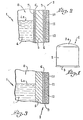
- a cartridge 1 or closed container containing a liquefied gas such as butane which is intended to be associated with a portable lighting, cooking, welding and similar apparatus. It is constituted by a cylindrical wall 2, the upper part of which is closed by a dome 2a while its lower part is closed by an added base 3 crimped relative to the base of the wall 2.
- the manufacture of such a cartridge is carried out in two separate operations.
- the first consists in cutting and stamping a strip or sheet of multilayer plastic material identi than that illustrated in fig. 2 to form the wall 2 and its dome 2a, while this hollow part is then turned over to be filled with liquid gas, the second operation comprises closing the hollow part from the bottom 3.
- Fig. 2 corresponds to a partial section of the wall 2 made in the immediate vicinity of the surface of the liquefied gas 4 contained in the cartridge 1. Of course, the latter is not completely filled so that the level 4a of the liquid is generally found slightly below the junction of the wall 2 with the dome 2a.
- the wall 2 consists of a metal core 5 consisting of a thin sheet of mild steel, the two faces of which are each protected by a layer 6 of non-ferrous metal such as tin.
- the assembly of the sheet 5 and its coatings 6 is called in the tinplate technique.
- the inner coating 6 of non-ferrous metal itself receives a layer 7 of protective varnish intended to isolate said coating from the useful content of the cartridge.
- the outer coating 6 of the sheet 5 receives a bonding varnish 9 facilitating the adhesion of a film of paint 10 entirely covering the wall 2 and its dome 2a.
- This film of paint constitutes support for inscriptions represented by the thickness 11.
- a coating 12 is applied to the entire outer surface of the wall 2 and its dome in order to constitute general protection.
- the starting point is a metallic product, known per se, in the form of a sheet or strip, without internal coating 6 and without layer 7 of protective varnish.
- This material is intended for the production of cartridges such as that 1 shown in FIG. 1.
- Fig. 3 is a view similar to that of FIG. 2; it shows that nothing has been changed with regard to the external face of the sheet 5, since there is its non-ferrous metallic coating 6, the layer 9 of bonding varnish, the film 10 of paint, the thickness 11 corresponding to the inscriptions, and finally the coating 12.
- Against the inner face of the sheet 5 is bare to be directly in contact, on the one hand with the liquefied gas 4, and on the other hand with the gas which is in space 8.
- the invention can also be applied to the packaging of aerosols in general, which can accept slight internal corrosion, to boxes, cans, cartridges, etc. of neutral products (that is to say non-aggressive), solid, liquid or gaseous, under pressure or not, for example paints, oils and varnishes.
- neutral products that is to say non-aggressive
- solid, liquid or gaseous under pressure or not, for example paints, oils and varnishes.
Landscapes
- Engineering & Computer Science (AREA)
- Mechanical Engineering (AREA)
- General Engineering & Computer Science (AREA)
- Packages (AREA)
- Filling Or Discharging Of Gas Storage Vessels (AREA)
- Laminated Bodies (AREA)
Description
- La présente invention est relative à divers emballages métalliques fermés, à usage unique, remplis avec un produit consommable, et dont au moins une paroi est constituée en tout ou partie par une tôle d'acier doux.
- Afin d'illustrer l'invention, on la décrira en référence à la fabrication de cartouches de petite capacité, à usage unique, perforables, et contenant un gaz de pétrole liquéfié, par exemple du butane.
- La présente demanderesse a déjà fabriqué et commercialisé de telles cartouches à des millions d'exemplaires pour l'alimentation d'appareils portatifs d'éclairage, de cuisson, de soudage, etc...
- La matière première permettant d'obtenir ces emballages perdus de gaz liquéfié est en général une tôle d'acier doux de faible épaisseur dont les deux faces sont pourvues d'un revêtement protecteur permanent contre la corrosion, qu'il s'agisse d'oxydation atmosphérique ou d'attaque par d'autres produits. La protection est réalisée de chaque côté de la tôle d'acier par une couche de très faible épaisseur d'un métal ou alliage inoxydable tel que l'étain, le chrome, le nickel, etc... Lorsqu'il s'agit d'étain, la matière première en question est généralement appelée fer blanc. On applique sur la couche de métal inoxydable une ou plusieurs couches de vernis de protection ou de finition.
- La matière première précédente est ensuite façonnée, par exemple par découpage et emboutissage, pour réaliser des emballages à usage unique qui sont ensuite remplis avec du butane liquéfié et fermés par un fond serti.
- On obtient ainsi des cartouches qui ne sont pas en règle générale attaquées de l'intérieur par leur contenu, à savoir l'hydrocarbure liquéfié, étant donné le caractère inerte de ce dernier. Mais dans certains cas particuliers, elles sont soumises néanmoins à une oxydation interne, c'est-à-dire initiée à partir du contenu de la cartouche, et qui progresse vers l'extérieur. Le cas d'une oxydation externe provenant de l'air ambiant n'est pas envisagé dans les présentes.
- Les conditions nécessaires au développement d'une oxydation interne, dans les cas particuliers précités, se rencontrent notamment dans les situations suivantes :
- 1. Le revêtement protecteur intérieur peut présenter des discontinuités ponctuelles ou quasi ponctuelles, résultant soit de défauts dans la fabrication du fer blanc, par exemple de défauts d'étincelage, soit de détériorations occasionnées par son façonnage, par exemple écaillage ou fissurage du revêtement au moment de l'emboutissage, notamment aux endroits où la feuille travaille à froid de manière importante.
- 2. Hormis le butane, le contenu de la cartouche présente toujours un certain nombre d'impuretés introduites en quantités infinitésimales au moment du remplissage ; parmi ces impuretés, on peut citer l'oxygène de l'air présent à l'état gazeux dans le ciel de la cartouche, et à l'état dissous dans le butane liquide. Par exemple, dans une cartouche d'environ 200 g de butane, se trouvent ainsi introduits au total environ 15 mg d'oxygène. De la même manière, de l'eau en très faible quantité est insérée dans la cartouche au moment du remplissage, notamment à partir de l'air atmosphérique.
- Au total, dans les cas particuliers précités, toutes les conditions pour une attaque électrochimique interne de la tôle métallique sont réunies, et l'on assiste alors au développement de points d'oxydation progressant de manière rayonnante vers l'extérieur de la cartouche. De tels points de corrosion peuvent se développer au point de percer de part en part la tôle métallique qui est en général de faible épaisseur, par exemple de l'ordre de quelques dixièmes de millimètres dans ces cas extrêmes, on aboutit alors à des micro-fuites de gaz butane, évidemment inacceptables pour des raisons de sécurité.
- La présente invention se propose de trouver une solution permettant de diminuer de manière substantielle les risques d'oxydation interne, tels qu'exposés précédemment.
- Suivant la présente invention, on a découvert que l'on diminuait ces risques en supprimant le revêtement protecteur permanent, et notamment la couche de métal ou alliage inoxydable, qui existent normalement du côté intérieur des emballages considérés précédemment. Et par conséquent, selon l'invention on obtient des emballages comportant du côté intérieur, soit une face nue en contact direct avec le produit consommable, soit une face initialement revêtue par un enduit non métallique, assurant une protection temporaire contre l'eau et l'oxygène avant façonnage et remplissage de l'emballage, la tôle étant à terme et du côté intérieur en contact avec le produit ; dans chacun de ces cas, le produit emballé n'est pas agressif à l'égard de l'acier doux.
- Pour la fabrication de cartouches de butane, on aboutit ainsi à des récipients perforables et à usage unique ne présentant du côté interne aucune protection effective, au sens de l'absence d'au moins une couche d'un matériau réellement efficace contre oxydation, par exemple un métal inoxydable.
- Conformément à l'invention, on a en effet découvert de manière surprenante que l'élimination de toute protection contre l'oxydation de la face intérieure diminuait ses risques de corrosion interne, tels qu'exposés précédemment. En effet, toute la surface intérieure de la cartouche, et non plus quelques discontinuités internes, ponctuelles ou quasi ponctuelles, se trouve exposée à l'action de la quantité infinitésimale d'oxygène présente dans le contenu de la cartouche. On opère ainsi, en quelque sorte, une dilution de l'oxygène présent dans la cartouche par rapport à toute la surface intérieure de celle-ci, au lieu de concentrer la même quantité d'agent oxydant sur quelques points de très faible superficie. Dans ces conditions, la quantité d'oxygène disponible dans une cartouche est insuffisante pour transformer la tôle métallique en oxyde ferreux ou ferrique sur toute sa surface intérieure et dans toute son épaisseur. On assiste seulement à une corrosion superficielle, donc très limitée en épaisseur, de toute la surface intérieure précitée, alors que, précédemment à l'invention, pour une surface très limitée des défauts de protection interne, la quantité d'oxygène disponible était très largement suffisante pour oxyder toute l'épaisseur de la tôle métallique.
- Bien entendu, le mécanisme de corrosion interne expliqué plus haut ne vaut que pour une oxydation, et suppose que le contenu de la cartouche est inerte par ailleurs, c'est-à-dire, n'exerce aucune action agressive contre la tôle métallique mise à nue.
- Concernant les réservoirs métalliques rechargeables, par exemple destinés à contenir des gaz de pétrole liquéfiés, il est connu de laisser nue la face interne de la tôle utilisée ; c'est par exemple ce que montre la demande de brevet français publiée sous le n° 2 291 446. Dans ce secteur technique, le contact direct de la tôle (du côté intérieur) et des traces éventuelles d'eau et d'oxygène ne soulève dans la pratique aucune difficulté, car ou il est prévu au moment de la conception et de la fabrication une surépaisseur de métal, dite de corrosion, destinée à être consommée par cette dernière pendant la durée de vie du réservoir, ou le métal utilisé est lui-même inoxydable.
- Outre la diminution de prix de la matière première nécessaire à la fabrication des cartouches, l'invention apporte en outre les avantages essentiels suivants :
- 1. Le façonnage du produit selon l'invention, notamment par emboutissage, peut se trouver facilité puisqu'il peut être moins soigné et précis qu'auparavant, du fait qu'on n'a plus à se préoccuper du maintien d'une continuité absolue de la protection permanente.
- 2. Pour des emballages à usage unique, ceux-ci une fois vides peuvent s'auto-détruire plus aisément, puisqu'en présence d'air atmosphérique, une corrosion totale par l'intérieur se propage très rapidement.
- Le dessin annexé, donné à titre d'exemple, permettra de mieux comprendre l'invention, les caractéristiques qu'elle présente et les avantages qu'elle est susceptible de procurer :
- Figure 1 est une vue en élévation d'une cartouche réalisée au moyen d'un matériau suivant l'invention.
- Figure 2 est une coupe partielle à grande échelle de la paroi d'une cartouche réalisée de manière classique.
- Figure 3 est une vue semblable à celle de fig. 2 mais illustrant une paroi établie conformément à l'invention pour constituer la cartouche de fig. 1.
- La fabrication et l'obtention d'emballages à usage unique remplis avec un produit inerte consommable, pose évidemment le problème de l'oxydation intermédiaire et temporaire de la face nue du matériau utilisé selon l'invention, tant que celui-ci n'est pas façonné et refermé sur lui-même, à l'état de cartouche, boîte, etc.
- Ce problème peut être résolu de différentes façons.
- On peut tout d'abord effectuer en continu, c'est-à-dire sans temps mort important entre les différentes opérations, l'obtention de la tôle d'acier comportant au moins d'un côté une face nue, le façonnage et le remplissage. Ceci suppose évidemment une organisation industrielle verticale des différentes opérations, dès l'obtention de la matière première de l'invention.
- Ensuite dans le cas où l'opération d'obtention de la tôle d'acier nue d'au moins un côté d'ine part, et les opérations de façonnage et remplissage d'autre part, ne peuvent pas être effectuées en continu, la tôle, recouverte par exemple, par un revêtement permanent d'un côté, est protégée temporairement de l'autre côté, avant façonnage et remplissage, contre toute oxydation. Cette protection temporaire peut être obtenue de différentes manières. Tout d'abord, la tôle d'acier telle que décrite précédemment, sous forme de demi- produit, peut être emballée à la sortie de l'unité de fabrication correspondante, dans un film plastique étanche, rempli éventuellement avec une atmosphère inerte. Ensuite,-la face nue de la tôle peut être recouverte par un enduit protecteur temporaire contre l'oxydation, de nature non métallique, par exemple matériau dit pelable ; subséquemment, l'enduit peut être éliminé avant que l'emballage soit complètement refermé sur lui-même, en présence du produit consommable, et dans ce cas l'enduit est éliminé immédiatement avant ou au cours du processus de façonnage et remplissage, par exemple en arrachant le matériau pelable ; ou subséquemment, l'enduit peut subsister du côté intérieur dans l'emballage terminé, contenant le produit consommable, c'est-à-dire après terminaison du processus de façonnage et remplissage, et dans ce cas, le produit consommable est à terme en contact avec la tôle métallique, soit parce que l'enduit est progressivement traversé par ledit produit et les agents de corrosion en quantité infinitésimale, soit parce que l'enduit disparaît dans le produit consommable, par exemple par dissolution dans ce dernier.
- On a représenté en fig. 1 une cartouche 1 ou récipient fermé renfermant un gaz liquéfié tel que le butane, et qui est destiné à être associé à un appareil portatif d'éclairage, de cuisson, de soudage et analogues. Elle est constituée par une paroi cylindrique 2 dont la partie supérieure est fermée par un dôme 2a tandis que sa partie inférieure est obturée par un fond rapporté 3 serti par rapport à la base de la paroi 2.
- La fabrication d'une telle cartouche s'effectue en deux opérations distinctes. La première consiste à découper et à emboutir une bande ou feuille de matière plastique multicouche identique à celle illustrée en fig. 2 pour former la paroi 2 et son dôme 2a, tandis qu'ensuite cette pièce crèuse est retournée pour être remplie de gaz liquide, la seconde opération comprend la fermeture de la pièce creuse par le fond 3.
- La fig. 2 correspond à une coupe partielle de la paroi 2 effectuée au voisinage immédiat de la surface du gaz liquéfié 4 que contient la cartouche 1. Bien entendu, celle-ci n'est pas complètement remplie si bien que le niveau 4a du liquide se trouve généralement en peu en dessous de la jonction de la paroi 2 avec le dôme 2a. La paroi 2 est constituée d'une âme métallique 5 consistant en une tôle mince d'acier doux dont les deux faces sont chacune protégées par une couche 6 de métal non ferreux tel que que l'étain. L'ensemble de la tôle 5 et de ses revêtements 6 est appelé dans la technique fer blanc. Le revêtement intérieur 6 de métal non ferreux reçoit lui-même une couche 7 de vernis protecteur destiné à isoler ledit revêtement du contenu utile de la cartouche. Le revêtement extérieur 6 de la tôle 5 reçoit un vernis d'accrochage 9 facilitant l'adhérence d'une pellicule de peinture 10 recouvrant entièrement la paroi 2 et son dôme 2a. Cette pellicule de peinture constitue support pour des inscriptions représentées par l'épaisseur 11. Enfin un enduit 12 est appliqué sur toute la surface extérieure de la paroi 2 et son dôme en vue de constituer une protection générale.
- Comme on l'a expliqué plus haut, suivant l'invention, on part d'un produit métallique, connu en soi, sous forme de feuille ou de bande, sans revêtement intérieur 6 et sans couche 7 de vernis protecteur. Ce matériau est destiné à la réalisation de cartouches telles que celle 1 représentée en fig. 1. La fig. 3 est une vue semblable à celle de fig. 2 ; elle montre que rien n'a été changé en ce qui concerne la face extérieure de la tôle 5, puisqu'on retrouve son revêtement métallique non ferreux 6, la couche 9 de vernis d'accrochage, la pellicule 10 de peinture, l'épaisseur 11 correspondant aux inscriptions, et enfin l'enduit 12. Par contre la face intérieure de la tôle 5 est nue pour être directement en contact, d'une part avec le gaz liquéfié 4, et d'autre part avec le gaz qui se trouve dans l'espace 8.
- En dehors des cartouches de butane, l'invention peut aussi être appliquée au conditionnement des aérosols en général, pouvant accepter une légère corrosion interne, aux boîtes, bidons, cartouches, etc... de produits neutres (c'est-à-dire non agressifs), solides, liquides ou gazeux, sous pression ou non, par exemple de peintures, huiles et vernis.
Claims (5)
1. Emballage fermé, à usage unique, comprenant une paroi en tôle d'acier doux, et contenant un produit consommable avec des quantités infinitésimales d'oxygène et d'eau, caractérisé en ce que, du côté intérieur, la tôle comporte une face nue en contact direct avec le produit, ce dernier étant non agressif à l'égard de l'acier doux.
2. Emballage fermé, à usage unique, comprenant une paroi en tôle d'acier doux, et contenant un produit consommable avec des quantités infinitésimales d'oxygène et d'eau, caractérisé en ce que, du côté intérieur, la tôle initialement revêtue par un enduit non métallique temporaire de protection contre l'eau et l'oxygène avant façonnage et remplissage est à terme en contact avec le produit consommable, ce dernier étant non agressif à l'égard de l'acier doux.
3. Emballage selon la revendication 2, caractérisé en ce que l'enduit temporaire de protection est soluble dans le produit consommable.
4. Emballage selon l'une quelconque des revendications 1 à 3, caractérisé en ce que le produit consommable est un gaz de pétrole liquéfié.
5. Emballage selon la revendication 4, caractérisé en ce qu'il a la forme d'une cartouche perforable.
Applications Claiming Priority (2)
| Application Number | Priority Date | Filing Date | Title |
|---|---|---|---|
| FR7837066A FR2444560A1 (fr) | 1978-12-18 | 1978-12-18 | Nouveau produit metallique sous forme de feuille, notamment pour la fabrication de divers emballages |
| FR7837066 | 1978-12-18 |
Publications (2)
| Publication Number | Publication Date |
|---|---|
| EP0013251A1 EP0013251A1 (fr) | 1980-07-09 |
| EP0013251B1 true EP0013251B1 (fr) | 1983-06-22 |
Family
ID=9216811
Family Applications (2)
| Application Number | Title | Priority Date | Filing Date |
|---|---|---|---|
| EP19790420070 Expired EP0013251B1 (fr) | 1978-12-18 | 1979-12-18 | Emballage fermé, à usage unique |
| EP19800900045 Expired EP0020687B1 (fr) | 1978-12-18 | 1980-07-01 | Emballage ferme, a usage unique |
Family Applications After (1)
| Application Number | Title | Priority Date | Filing Date |
|---|---|---|---|
| EP19800900045 Expired EP0020687B1 (fr) | 1978-12-18 | 1980-07-01 | Emballage ferme, a usage unique |
Country Status (7)
| Country | Link |
|---|---|
| EP (2) | EP0013251B1 (fr) |
| JP (1) | JPS6358318B2 (fr) |
| DE (1) | DE2966290D1 (fr) |
| ES (1) | ES254280Y (fr) |
| FR (1) | FR2444560A1 (fr) |
| GR (1) | GR67000B (fr) |
| WO (1) | WO1980001312A1 (fr) |
Families Citing this family (3)
| Publication number | Priority date | Publication date | Assignee | Title |
|---|---|---|---|---|
| US5330091A (en) * | 1992-10-09 | 1994-07-19 | The Boc Group, Inc. | Seamless cylinder shell construction |
| CN106704819A (zh) * | 2017-03-01 | 2017-05-24 | 苟仲武 | 一种基于液态气体驱动的蒸汽机车系统及其使用方法 |
| CN114321698B (zh) * | 2021-12-30 | 2022-07-19 | 大连科利德光电子材料有限公司 | 一种用于储存电子级一氧化氮的钢瓶及其加工方法 |
Family Cites Families (10)
| Publication number | Priority date | Publication date | Assignee | Title |
|---|---|---|---|---|
| DE718995C (de) * | 1939-03-23 | 1942-03-26 | Bandeisenwalzwerke Ag | Vorrichtung zum einseitigen Verzinnen von Metallbaendern, Blechen o. dgl. |
| FR923246A (fr) * | 1946-01-28 | 1947-07-01 | Procédé et dispositif pour le recouvrement de tôles à l'aide de métaux non ferreux | |
| US3035926A (en) * | 1960-01-04 | 1962-05-22 | Morris P Kirk & Son Inc | Protective composition for metals |
| FR1478771A (fr) * | 1966-05-03 | 1967-04-28 | American Can Co | Procédé pour former un récipient cylindrique |
| DE1801983A1 (de) * | 1968-07-22 | 1970-04-30 | Wahl Fa Jacob | Verfahren zum Schuetzen von Metalloberflaechen waehrend der Umformungsstufe |
| US3936549A (en) * | 1972-11-17 | 1976-02-03 | The Kohler Coating Machinery Corporation | Method and apparatus for applying a liquid coating to strip material |
| JPS5119906A (ja) * | 1974-08-12 | 1976-02-17 | Oki Electric Ind Co Ltd | Jidodenwakokanshisutemu |
| GB1495259A (en) * | 1974-11-15 | 1977-12-14 | Fulmer Res Inst Ltd | Gas containers |
| FR2304022A1 (fr) * | 1975-03-11 | 1976-10-08 | Grenoble Toleries | Pour perfectionnements apportes a la fabrication de recipients metalliques pour fluides sous pression |
| JPS5255417A (en) * | 1975-10-31 | 1977-05-06 | Nec Corp | Automatic exchange connection system |
-
1978
- 1978-12-18 FR FR7837066A patent/FR2444560A1/fr active Granted
-
1979
- 1979-12-14 DE DE8080900045T patent/DE2966290D1/de not_active Expired
- 1979-12-14 WO PCT/FR1979/000126 patent/WO1980001312A1/fr not_active Ceased
- 1979-12-14 JP JP55500096A patent/JPS6358318B2/ja not_active Expired
- 1979-12-18 EP EP19790420070 patent/EP0013251B1/fr not_active Expired
- 1979-12-18 GR GR60797A patent/GR67000B/el unknown
- 1979-12-18 ES ES1979254280U patent/ES254280Y/es not_active Expired
-
1980
- 1980-07-01 EP EP19800900045 patent/EP0020687B1/fr not_active Expired
Also Published As
| Publication number | Publication date |
|---|---|
| JPS55501031A (fr) | 1980-11-27 |
| EP0020687B1 (fr) | 1983-10-05 |
| JPS6358318B2 (fr) | 1988-11-15 |
| ES254280Y (es) | 1981-09-16 |
| EP0020687A1 (fr) | 1981-01-07 |
| WO1980001312A1 (fr) | 1980-06-26 |
| ES254280U (es) | 1981-02-16 |
| EP0013251A1 (fr) | 1980-07-09 |
| FR2444560B1 (fr) | 1982-02-19 |
| DE2966290D1 (en) | 1983-11-10 |
| FR2444560A1 (fr) | 1980-07-18 |
| GR67000B (fr) | 1981-05-18 |
Similar Documents
| Publication | Publication Date | Title |
|---|---|---|
| CA2597693C (fr) | Dispositif apte a delivrer des fluides, notamment medicamenteux sous pression | |
| FR2607109A1 (fr) | Bouteille a volume variable specialement en matiere plastique et son procede de fabrication | |
| FR2802180A1 (fr) | Dispositif formant un recipient permettant de conserver separement deux substances differentes | |
| EP0088731A1 (fr) | Soupape pour l'évacuation de la vapeur d'un contenant | |
| FR2584941A1 (fr) | Cartouche tubulaire filtrante et son application a la fabrication de vin mousseux en bouteille | |
| EP0013251B1 (fr) | Emballage fermé, à usage unique | |
| FR2716669A1 (fr) | Procédé de vidage d'un flacon et élément de bouchage conforme pour sa mise en Óoeuvre. | |
| FR2522308A1 (fr) | Baril en carton, etanche aux liquides, procede et dispositif pour sa fabrication | |
| EP3697548B1 (fr) | Couvercle pour boîte de conserve métallique, comprenant un anneau métallique et membrane pelable thermoscellée | |
| EP0642875B1 (fr) | Procédé et installation de fabrication et d'assemblage de bouteilles, notamment à gaz liquéfié, ainsi que de telles bouteilles | |
| EP1412263B1 (fr) | Dispositif a recipient rigide et poche cylindrique souple pour le conditionnement de fluides. | |
| EP1279885A1 (fr) | Procédé d'isolation thermique d'une structure metallique dont les deux faces sont soumises à des températures cryogéniques | |
| WO2003042049A1 (fr) | Recipient pour liquide et bouchon pour un tel recipient | |
| EP1765688A1 (fr) | Joints d"etancheite en materiau multicouche pour moyen de bouchage, typiquement pour une capsule de bouchage | |
| FR2557544A1 (fr) | Procede et dispositif pour la protection de substances perissables contenues dans des recipients contre l'influence de gaz nocifs, par exemple l'air de l'atmosphere | |
| BE852384A (fr) | Capsule et procede de fermeture | |
| FR2563187A1 (fr) | Boite combinee | |
| EP0029039A1 (fr) | Recipient a parois souples pour produits sous pression. | |
| EP1172303B1 (fr) | Capsule de bouchage à jupe plissée et joint pour bouteille de boisson gazeuse | |
| WO2008056056A1 (fr) | Joints d'etancheite en materiau multicouche pour moyen de bouchage, typiquement pour une capsule de bouchage | |
| EP4450133B1 (fr) | Dose flottante d'additif pour un extincteur à eau | |
| JP2008087846A (ja) | プラスチック容器 | |
| FR2555498A1 (fr) | Procede de fabrication d'un corps creux comportant une enveloppe externe moulee en caoutchouc et corps creux ainsi realises | |
| EP0039753A1 (fr) | Générateur de gaz pour cultures anaérobies | |
| FR2981335A1 (fr) | Perfectionnement aux contenants hermetiques destines a contenir une boisson gazeuse |
Legal Events
| Date | Code | Title | Description |
|---|---|---|---|
| PUAI | Public reference made under article 153(3) epc to a published international application that has entered the european phase |
Free format text: ORIGINAL CODE: 0009012 |
|
| AK | Designated contracting states |
Designated state(s): IT |
|
| 17P | Request for examination filed |
Effective date: 19801223 |
|
| ITF | It: translation for a ep patent filed | ||
| GRAA | (expected) grant |
Free format text: ORIGINAL CODE: 0009210 |
|
| AK | Designated contracting states |
Designated state(s): IT |
|
| PLBE | No opposition filed within time limit |
Free format text: ORIGINAL CODE: 0009261 |
|
| STAA | Information on the status of an ep patent application or granted ep patent |
Free format text: STATUS: NO OPPOSITION FILED WITHIN TIME LIMIT |
|
| 26N | No opposition filed |