EP0013256A1 - Appareil à défroisser les tissus - Google Patents
Appareil à défroisser les tissus Download PDFInfo
- Publication number
- EP0013256A1 EP0013256A1 EP79810140A EP79810140A EP0013256A1 EP 0013256 A1 EP0013256 A1 EP 0013256A1 EP 79810140 A EP79810140 A EP 79810140A EP 79810140 A EP79810140 A EP 79810140A EP 0013256 A1 EP0013256 A1 EP 0013256A1
- Authority
- EP
- European Patent Office
- Prior art keywords
- handle
- plug
- outlet
- water
- fabrics
- Prior art date
- Legal status (The legal status is an assumption and is not a legal conclusion. Google has not performed a legal analysis and makes no representation as to the accuracy of the status listed.)
- Granted
Links
- 239000004744 fabric Substances 0.000 title claims description 13
- XLYOFNOQVPJJNP-UHFFFAOYSA-N water Substances O XLYOFNOQVPJJNP-UHFFFAOYSA-N 0.000 claims abstract description 15
- 238000001816 cooling Methods 0.000 claims abstract description 4
- 238000009499 grossing Methods 0.000 claims description 8
- 238000010438 heat treatment Methods 0.000 claims description 3
- 238000005485 electric heating Methods 0.000 claims 1
- 230000000903 blocking effect Effects 0.000 abstract 1
- 238000007789 sealing Methods 0.000 abstract 1
- 238000009792 diffusion process Methods 0.000 description 1
- 230000000717 retained effect Effects 0.000 description 1
Images
Classifications
-
- D—TEXTILES; PAPER
- D06—TREATMENT OF TEXTILES OR THE LIKE; LAUNDERING; FLEXIBLE MATERIALS NOT OTHERWISE PROVIDED FOR
- D06F—LAUNDERING, DRYING, IRONING, PRESSING OR FOLDING TEXTILE ARTICLES
- D06F75/00—Hand irons
- D06F75/30—Hand irons of special external shape or form
-
- D—TEXTILES; PAPER
- D06—TREATMENT OF TEXTILES OR THE LIKE; LAUNDERING; FLEXIBLE MATERIALS NOT OTHERWISE PROVIDED FOR
- D06F—LAUNDERING, DRYING, IRONING, PRESSING OR FOLDING TEXTILE ARTICLES
- D06F87/00—Apparatus for moistening or otherwise conditioning the article to be ironed or pressed
Definitions
- the present invention relates to an apparatus for smoothing fabrics.
- a common appliance for smoothing fabrics consists of a body and a handle fixed on this body making it possible to hold and pass the said appliance over the fabrics to be smoothed.
- the body forms a reservoir of water energized and thus heated using two electrodes, said water being introduced by means of an opening made in said body.
- the latter further comprises a flat surface, which is provided on the one hand with orifices allowing the diffusion of the value of the heated water and on the other hand with a transverse brush.
- the invention proposes, by an adequate safety device, to eliminate this drawback by preventing the filling of the appliance when the latter is energized and to present an appliance for smoothing compared to existing ones.
- the subject of the invention is an apparatus for smoothing fabrics, comprising a body forming a water reservoir and provided with a handle and a transverse brush, means for electrically heating the water in this body, orifices for the outlet of the steam thus produced and which is projected onto the fabric to be smoothed.
- the apparatus is arranged so as to present at one of its ends means for fixing this handle to the body and means for closing the opening for filling the body and at its other end, means for fixing to the body of the device and an access opening, located opposite a cavity containing the outlet for supplying current to the electrical heating means, for the passage of an electrical plug intended to cooperate with the outlet, this plug preventing removal of the handle as long as it cooperates with the socket.
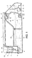
- Figs. 1 and 2 illustrate the apparatus for smoothing fabrics according to the invention. It consists of a handle 1 and a body 2 forming a reservoir 3 containing water 4. The energized water is heated using the electrodes 5 connected by the wires 6 to the contactors' 7 housed in a cavity 8 forming a socket for receiving the plug (not shown in fig. 1 and 2) to connect the device to the network.
- the water 4 gives off steam and this is diffused towards the outside by a duct 9 through a plate 10 provided with outlet orifices 11.
- the duct 9 formed from the wall 12 widens towards the outlet to receive the plate 10 and thus forms a chamber 24 in contact with the reservoir 3 by the said conduit 9.
- the said conduit 9 and the said chamber 24 are arranged in such a way that water cannot reach them when the apparatus to smooth the fabrics is in the working position as shown in fig. 1.
- a ball 13 housed in this chamber 24 is retained by the plate 10 so as to form a safety valve as we will see later.
- the plate 10 forms the extension of the face 14 of the body 2 of the device.
- an emerging transverse brush 15 is located on this face 14.
- the object of the invention is to prevent filling the tank 3 while the appliance is connected.
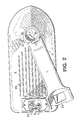
- the filling opening 16 was made to coincide with the end 17 of the handle 1, the said handle being able to pivot around its end 16 as shown in FIG. 2.
- the part 18 of the filling opening 16 is wedged between a locking finger 19 and a circular part 20 forming the plug of the filling opening 16.
- the part 18 forming the retaining element of the end 17 of the handle 1 represents only a part of the circular surface of the bottom of the filling opening 16 so that when the handle 1 pivots in the direction of the arrow as shown in FIG. 2, around its end 17, the latter is released, opening the filling opening 16.
- the end 21 of the handle 1 must be able to move. This is only possible if the plug housed in the cavity 8 has been removed beforehand, thereby releasing the end 21.
- the end 21 is arranged so as to have an opening 22 allowing the plug passing through the cavity 8. This plug beyond said cavity 8 thus fixedly retains the end 21 of the handle 1 then being in the position of FIG. 1.
- a stop 23 with a rim in contact with the end 21 of the handle 1 makes it possible to limit the vertical and pivoting movement of said handle 1, thus firmly fixing the end 21 of said handle when the plug is set.
- the handle 1 has been designed so as to release the filling opening 16 only if the plug housed in the cavity 8 forming a socket has been removed beforehand, thus allowing the handle 1 to pivot.
- Another safety device has been incorporated into the device for smoothing fabrics.
- the ball 13 housed in the chamber 24 prevents, when it moves in 13 ', from filling the reservoir through the conduit 9, the movement in 13' of the ball being automatic when the device is turned over so as to be filled by the outlet orifices 11 of the plate 10.
- cooling fins 25 have been incorporated into the body 2 of the device. These cooling fins 25 allow the user to avoid burning himself when his hand comes into contact with the body 2 of the device containing the water heated by the electrodes 5.
- the apparatus for smoothing the fabrics of the invention while being simple to use, presents clearly improved safety conditions compared to the previous apparatuses.
Landscapes
- Engineering & Computer Science (AREA)
- Textile Engineering (AREA)
- Treatment Of Fiber Materials (AREA)
- Cookers (AREA)
Abstract
Description
- La présente ipvention concerne un appareil à défroisser les tissus.
- Un appareil usuel à défroisser les tissus se compose d'un corps et d'une poignée fixée sur ce corps permettant de tenir et de faire passer le dit appareil sur les tissus à défroisser. Le corps forme un réservoir d'eau mise sous tension et chauffée ainsi à l'aide de deux électrodes, la dite eau étant introduite au moyen d'une ouverture pratiquée dans le dit corps. Ce dernier comporte en outre une surface plane, laquelle est munie d'une part d'orifices permettant la diffusion de la valeur de l'eau chauffée et d'autre part d'une brosse transversale. Ainsi, par la conjonction de l'action de la brosse et de la vapeur diffusée, les tissus peuvent être défroissés.
- Ces appareils présentent néanmoins de tels inconvénients qu'ils peuvent devenir dangereux pour l'homme. En effet, l'utilisateur peut sans autre remplir l'appareil d'eau par l'ouverture pratiquée à cet effet alors que l'appareil reste branché sur le réseau. L'eau étant sous tension, l'utilisateur risque l'électrocution au moment du remplissage.
- L'invention propose par un dispositif de sécurité adéquat de supprimer cet inconvénient en empêchant le remplissage de l'appareil lorsque celui-ci est sous tension et de présenter un appareil à défroisser amélioré par rapport à ceux existants.
- En effet, l'invention a pour objet un appareil à défroisser les tissus, comprenant un corps formant réservoir d'eau et muni d'une poignée et d'une brosse transversale, des moyens de chauffage électrique de l'eau dans ce corps, des orifices pour la sortie de la vapeur ainsi produite et que l'on projette sur le tissu à défroisser. L'appareil est agencé de manière à présenter à l'une de ses extrémités des moyens de fixation de cette poignée sur le corps et des moyens d'obturation de l'ouverture de remplissage du corps et à son autre extrémité, des moyens de fixation au corps de l'appareil et une ouverture d'accès, située en face d'une cavité contenant la prise d'amenée de courant aux moyens de chauffage électrique, pour le passage d'une fiche électrique destinée à coopérer avec la prise, cette fiche empêchant l'enlèvement de la poignée tant qu'elle coopère avec la prise.
- Les figures suivantes données à titre d'exemples représentent les formes d'exécution de l'appareil suivant l'invention.
- La fig. 1 représente l'appareil en coupe partielle,
- la fig. 2 représente une vue de dessus de l'appareil.
- Les fig. 1 et 2 illustrent l'appareil à défroisser les tissus selon l'invention. Il se compose d'une poignée 1 et d'un corps 2 formant un réservoir 3 contenant de l'eau 4. L'eau mise sous tension est chauffée à l'aide des électrodes 5 reliées par les fils 6 aux contacteurs'7 logés dans une cavité 8 formant une prise permettant de recevoir la fiche (non représentée sur les fig. 1 et 2) pour brancher l'appareil au réseau.
- L'eau 4 dégage de la vapeur et celle-ci est diffusée vers l'extérieur par un conduit 9 au travers d'une plaque 10 munie d'orifices de sortie 11. Le conduit 9 formé de la paroi 12 s'élargit vers la sortie pour recevoir la plaque 10 et forme ainsi une chambre 24 en contact avec le réservoir 3 par le dit conduit 9. Le dit conduit 9 et la dite chambre 24 sont agencés de telle manière que l'eau ne puisse les atteindre lorsque l'appareil à défroisser les tissus se trouve en position de travail comme le montre la fig. 1. Une bille 13 logée dans cette chambre 24 est retenue par la plaque 10 de manière à former une soupape de sécurité comme nous le verrons plus loin. La plaque 10 forme le prolongement de la face 14 du corps 2 de l'appareil. En outre, une brosse transversale 15 émergeante est située sur cette face 14.
- Le but de l'invention est d'empêcher de remplir le réservoir 3 pendant que l'appareil est branché. Pour cela on a fait coïncider l'ouverture de remplissage 16 avec l'extrémité 17 de la poignée 1, la dite poignée pouvant pivoter autour de son extrémité 16 comme le montre la fig. 2. Lorsque la poignée se trouve en position fermée comme le montre la fig. 1, la partie 18 de l'ouverture de remplissage 16 se trouve coincée entre un doigt de verrouillage 19 et une partie circulaire 20 formant le bouchon de l'ouverture de remplissage 16. La partie 18 formant l'élément de retenue de l'extrémité 17 de la poignée 1 ne représente qu'une partie de la surface circulaire du fond de l'ouverture de remplissage 16 de telle manière que lorsque la poignée 1 pivote dans le sens de la flèche comme le montre la fig. 2, autour de son extrémité 17, celle-ci se trouve libérée, débouchant l'ouverture de remplissage 16.
- Pour ce faire, il faut que l'extrémité 21 de la poignée 1 puisse se déplacer. Ceci n'est possible que si la fiche logée dans la cavité 8 a été préalablement enlevée, libérant ainsi l'extrémité 21. L'extrémité 21 est agencée de manière à comporter une ouverture 22 laissant passer la fiche se logeant dans la cavité 8. Cette fiche dépassant la dite cavité 8 retient ainsi fixement l'extrémité 21 de la poignée 1 se trouvant alors dans la position de la fig. 1. De plus, une butée 23 avec un rebord en contact avec l'extrémité 21 de la poignée 1 permet de limiter le mouvement vertical et pivotant de la dite poignée 1, fixant ainsi solidement l'extrémité 21 de la dite poignée lorsque la fiche est mise.
- On constate donc que la poignée 1 a été conçue de manière' à libérer l'ouverture de remplissage 16 seulement si la fiche logée dans la cavité 8 formant prise de courant a été préalablement enlevée, permettant ainsi à la poignée 1 de pivoter.
- Un autre dispositif de sécurité a été incorporé dans l'appareil à défroisser les tissus. En effet, la bille 13 logée dans la chambre 24 empêche, lorsqu'elle se déplace en 13', de remplir le réservoir par le conduit 9, le déplacement en 13' de la bille étant automatique lorsque l'appareil est retourné de manière à être rempli par les orifices de sortie 11 de la plaque 10.
- D'autre part, des ailettes de refroidissement 25 ont été incorporées au corps 2 de l'appareil. Ces ailettes de refroidissement 25 permettent à l'utilisateur d'éviter de se brûler lorsque sa main vient en contact avec le corps 2 de l'appareil contenant l'eau chauffée par les électrodes 5.
- Ainsi, l'appareil à défroisser les tissus de l'invention, tout en étant d'un usage simple, présente des conditions de sécurité nettement améliorées par rapport aux appareils antérieurs.
Claims (3)
Applications Claiming Priority (2)
| Application Number | Priority Date | Filing Date | Title |
|---|---|---|---|
| CH13029/78 | 1978-12-21 | ||
| CH1302978A CH626129A5 (fr) | 1978-12-21 | 1978-12-21 |
Publications (2)
| Publication Number | Publication Date |
|---|---|
| EP0013256A1 true EP0013256A1 (fr) | 1980-07-09 |
| EP0013256B1 EP0013256B1 (fr) | 1982-10-20 |
Family
ID=4388665
Family Applications (1)
| Application Number | Title | Priority Date | Filing Date |
|---|---|---|---|
| EP79810140A Expired EP0013256B1 (fr) | 1978-12-21 | 1979-10-31 | Appareil à défroisser les tissus |
Country Status (8)
| Country | Link |
|---|---|
| US (1) | US4366367A (fr) |
| EP (1) | EP0013256B1 (fr) |
| CA (1) | CA1132040A (fr) |
| CH (1) | CH626129A5 (fr) |
| DE (1) | DE2963899D1 (fr) |
| ES (1) | ES485702A1 (fr) |
| HK (1) | HK15185A (fr) |
| SG (1) | SG50083G (fr) |
Cited By (3)
| Publication number | Priority date | Publication date | Assignee | Title |
|---|---|---|---|---|
| EP0104048A3 (fr) * | 1982-09-22 | 1985-12-18 | Primeline (Imports) Limited | Appareil électrique à réservoir d'eau |
| EP0200807A1 (fr) * | 1984-06-14 | 1986-11-12 | Re Chin Zai | Combinaison aspirateur et fer à repasser à vapeur |
| EP2444543A4 (fr) * | 2009-06-16 | 2018-01-10 | Tsann Kuen (Zhangzhou) Enterprise Co., Ltd. | Fer électrique rotatif et machine à repasser à suspension le comportant |
Families Citing this family (33)
| Publication number | Priority date | Publication date | Assignee | Title |
|---|---|---|---|---|
| CA1208117A (fr) * | 1982-03-19 | 1986-07-22 | Marc Terraillon | Fer a repasser electrique |
| US4532411A (en) * | 1982-03-19 | 1985-07-30 | Marc Terraillon | Electric fabric steaming appliance having a detachable metallic sole-plate |
| US4496826A (en) * | 1983-02-14 | 1985-01-29 | Leonard Osrow | Hand-held shock-resistant electrolytically heated steam producing apparatus |
| US4536977A (en) * | 1984-03-21 | 1985-08-27 | Doyel John S | Portable, hand-held steaming or pressing device |
| US4688340A (en) * | 1985-01-16 | 1987-08-25 | Black & Decker Inc. | Travel steam and dry iron |
| USD294987S (en) | 1985-03-07 | 1988-03-29 | North American Philips Corporation | Fabric steamer |
| US4815224A (en) * | 1986-05-16 | 1989-03-28 | Sears, Roebuck & Company | Electric iron |
| USD307341S (en) | 1986-12-17 | 1990-04-17 | North American Philips Corp. | Fabric steamer |
| GB8909510D0 (en) * | 1989-04-29 | 1989-06-14 | Earlex Ltd | Steam generator |
| USD328163S (en) | 1991-08-28 | 1992-07-21 | E. Mishan & Sons, Inc. | Steamer handle |
| USD328164S (en) | 1991-08-28 | 1992-07-21 | E. Mishan & Sons, Inc. | Steamer body |
| DE4135650A1 (de) * | 1991-10-29 | 1993-05-06 | Braun Ag, 6000 Frankfurt, De | Buegeleisen |
| USD342814S (en) | 1991-11-04 | 1993-12-28 | 2331-0345 Quebec Inc. | Steam iron |
| USD340330S (en) | 1991-11-25 | 1993-10-12 | Seguljic Nicole M | Steam iron |
| DE4309241A1 (de) * | 1993-03-23 | 1994-09-29 | Wagner Gmbh J | Vorrichtung zum Ablösen von Tapeten |
| US5421110A (en) * | 1994-05-10 | 1995-06-06 | Black & Decker Inc. | Electric iron with reservoir fill-check float valve |
| US5404662A (en) * | 1994-05-10 | 1995-04-11 | Black & Decker Inc. | Steam iron with a vertical steaming feature |
| USD416655S (en) | 1998-09-29 | 1999-11-16 | Chun-Liang Lin | Electric iron |
| US7546701B2 (en) * | 2005-05-13 | 2009-06-16 | Ehsan Alipour | Automatic standby electric clothes iron |
| USD484654S1 (en) | 2003-04-17 | 2003-12-30 | E. Mishan & Sons, Inc. | Steamer |
| USD568017S1 (en) * | 2004-04-02 | 2008-04-29 | Goodway Electrical Co. Ltd. | Combined iron and accessory brush therefor |
| USD531774S1 (en) * | 2004-12-07 | 2006-11-07 | Euro Marketing 90 S.R.L. | Combined travel steam iron with brush or similar article |
| US20060191299A1 (en) * | 2004-12-15 | 2006-08-31 | Andrew Tobias | Garment steamer |
| WO2012054433A2 (fr) * | 2010-10-20 | 2012-04-26 | Euro-Pro Operating Llc | Centrale vapeur pour vêtements |
| CN201883321U (zh) * | 2010-11-26 | 2011-06-29 | 漳州灿坤实业有限公司 | 一种挂烫机蒸汽喷头 |
| RU2662209C2 (ru) * | 2013-08-26 | 2018-07-24 | Конинклейке Филипс Н.В. | Головка ручного отпаривателя |
| US20150191866A1 (en) | 2014-01-06 | 2015-07-09 | Techtronic Floor Care Technology Limited | Portable garment steamer |
| USD762935S1 (en) | 2015-09-24 | 2016-08-02 | Lior Dadon | Travel steamer |
| CN108360236B (zh) * | 2017-12-26 | 2023-10-20 | 宁波浩嘉电器有限公司 | 一种发热盘可旋转的蒸汽刷 |
| CN109058967B (zh) * | 2018-09-29 | 2024-10-01 | 奥佳华智能健康科技集团股份有限公司 | 一种具有蒸汽产生功能的装置 |
| USD845573S1 (en) * | 2018-12-07 | 2019-04-09 | Shenzhen Kean Digital Co., Ltd. | Iron |
| USD915696S1 (en) * | 2019-05-23 | 2021-04-06 | Shenzhen Simple-tech Electronic Technology Co., Ltd | Portable garment steamer |
| USD930925S1 (en) * | 2020-03-04 | 2021-09-14 | Conair Corporation | Garment steamer |
Citations (10)
| Publication number | Priority date | Publication date | Assignee | Title |
|---|---|---|---|---|
| DE573813C (de) * | 1930-09-03 | 1933-04-06 | Hermann Weiss | Elektrischer Verdampfer, bei dem die in den Fluessigkeitsbehaelter eintauchende Heizvorrichtung von dem abnehmbaren Behaelterdeckel getragen wird |
| US1927316A (en) * | 1928-01-03 | 1933-09-19 | Katzman Max | Electric vaporizer |
| US2384644A (en) * | 1941-05-08 | 1945-09-11 | Edward P Schreyer | Pressing iron |
| FR1017946A (fr) * | 1950-05-15 | 1952-12-22 | Fer à repasser ou appareil analogue | |
| FR2024201A1 (fr) * | 1968-11-25 | 1970-08-28 | Vilbiss Cy | |
| US3579262A (en) * | 1968-05-22 | 1971-05-18 | Champion Spark Plug Co | Electric steam vaporizer |
| US3646317A (en) * | 1970-11-02 | 1972-02-29 | Osrow Products Co Inc | Hand steaming device |
| GB1315083A (en) * | 1971-10-14 | 1973-04-26 | Raymond Ind Ltd | Device for use in cleaning or removing creases and wrinkles from materials |
| US3755649A (en) * | 1972-02-02 | 1973-08-28 | Osrow Prod Co Inc | Sewing steamer |
| GB1338108A (en) * | 1971-12-15 | 1973-11-21 | Doyel J S | Portable handheld steamer |
Family Cites Families (15)
| Publication number | Priority date | Publication date | Assignee | Title |
|---|---|---|---|---|
| US1806729A (en) * | 1931-05-26 | aitken | ||
| US1797457A (en) * | 1931-03-24 | Electric vaporizer | ||
| US1782069A (en) * | 1930-11-18 | henning | ||
| US1603425A (en) * | 1924-05-09 | 1926-10-19 | Steere Ernest Charles | Electric water heater |
| US1830875A (en) * | 1927-10-17 | 1931-11-10 | Izumiya Mata | Pressing iron |
| FR730065A (fr) | 1931-12-30 | 1932-08-05 | Dispositif électrique pourvu d'un interrupteur ou raccordement de sûreté, pour le chauffage ou la vaporisation d'un milieu | |
| US2076709A (en) * | 1933-01-30 | 1937-04-13 | Deutsch Simon | Spraying device |
| US2152122A (en) * | 1934-08-28 | 1939-03-28 | Fed Enameling & Stamping Compa | Automatic electric cooking utensil |
| US2323225A (en) * | 1940-09-03 | 1943-06-29 | James C Ledbetter | Steam pressing iron |
| US2385865A (en) * | 1943-02-04 | 1945-10-02 | Kollmeyer Margaret Agnes | Fountain brush |
| US2659989A (en) * | 1949-11-19 | 1953-11-24 | Casco Products Corp | Steam and dry flatiron |
| US2849736A (en) * | 1955-05-16 | 1958-09-02 | Albert G Kohle | Fabric steaming and brushing device |
| US3805425A (en) * | 1973-01-26 | 1974-04-23 | Rowenta Werke Gmbh | Brush devices |
| US3969607A (en) * | 1974-06-18 | 1976-07-13 | Osrow Products Company Inc. | Hand steaming device with automatic power interrupting means |
| US3997759A (en) * | 1974-11-18 | 1976-12-14 | Osrow Products Co., Inc. | Portable hand-manipulatable steamer for loosening the bond between wallpaper and a substrate |
-
1978
- 1978-12-21 CH CH1302978A patent/CH626129A5/fr not_active IP Right Cessation
-
1979
- 1979-10-31 DE DE7979810140T patent/DE2963899D1/de not_active Expired
- 1979-10-31 EP EP79810140A patent/EP0013256B1/fr not_active Expired
- 1979-11-05 ES ES485702A patent/ES485702A1/es not_active Expired
- 1979-11-15 US US06/094,659 patent/US4366367A/en not_active Expired - Lifetime
- 1979-11-21 CA CA340,308A patent/CA1132040A/fr not_active Expired
-
1983
- 1983-08-11 SG SG500/83A patent/SG50083G/en unknown
-
1985
- 1985-03-07 HK HK151/85A patent/HK15185A/xx unknown
Patent Citations (10)
| Publication number | Priority date | Publication date | Assignee | Title |
|---|---|---|---|---|
| US1927316A (en) * | 1928-01-03 | 1933-09-19 | Katzman Max | Electric vaporizer |
| DE573813C (de) * | 1930-09-03 | 1933-04-06 | Hermann Weiss | Elektrischer Verdampfer, bei dem die in den Fluessigkeitsbehaelter eintauchende Heizvorrichtung von dem abnehmbaren Behaelterdeckel getragen wird |
| US2384644A (en) * | 1941-05-08 | 1945-09-11 | Edward P Schreyer | Pressing iron |
| FR1017946A (fr) * | 1950-05-15 | 1952-12-22 | Fer à repasser ou appareil analogue | |
| US3579262A (en) * | 1968-05-22 | 1971-05-18 | Champion Spark Plug Co | Electric steam vaporizer |
| FR2024201A1 (fr) * | 1968-11-25 | 1970-08-28 | Vilbiss Cy | |
| US3646317A (en) * | 1970-11-02 | 1972-02-29 | Osrow Products Co Inc | Hand steaming device |
| GB1315083A (en) * | 1971-10-14 | 1973-04-26 | Raymond Ind Ltd | Device for use in cleaning or removing creases and wrinkles from materials |
| GB1338108A (en) * | 1971-12-15 | 1973-11-21 | Doyel J S | Portable handheld steamer |
| US3755649A (en) * | 1972-02-02 | 1973-08-28 | Osrow Prod Co Inc | Sewing steamer |
Cited By (3)
| Publication number | Priority date | Publication date | Assignee | Title |
|---|---|---|---|---|
| EP0104048A3 (fr) * | 1982-09-22 | 1985-12-18 | Primeline (Imports) Limited | Appareil électrique à réservoir d'eau |
| EP0200807A1 (fr) * | 1984-06-14 | 1986-11-12 | Re Chin Zai | Combinaison aspirateur et fer à repasser à vapeur |
| EP2444543A4 (fr) * | 2009-06-16 | 2018-01-10 | Tsann Kuen (Zhangzhou) Enterprise Co., Ltd. | Fer électrique rotatif et machine à repasser à suspension le comportant |
Also Published As
| Publication number | Publication date |
|---|---|
| HK15185A (en) | 1985-03-15 |
| ES485702A1 (es) | 1980-05-16 |
| SG50083G (en) | 1985-02-15 |
| CH626129A5 (fr) | 1981-10-30 |
| US4366367A (en) | 1982-12-28 |
| EP0013256B1 (fr) | 1982-10-20 |
| DE2963899D1 (en) | 1982-11-25 |
| CA1132040A (fr) | 1982-09-21 |
Similar Documents
| Publication | Publication Date | Title |
|---|---|---|
| EP0013256B1 (fr) | Appareil à défroisser les tissus | |
| EP2503053B1 (fr) | Appareil de repassage comportant une cavité de rangement d'un cordon | |
| EP3467193B1 (fr) | Appareil de défroissage équipé d'une chambre de vaporisation munie d'un orifice de nettoyage | |
| FR2795334A1 (fr) | Baton de ski | |
| FR2500018A1 (fr) | Fer a repasser a vapeur | |
| MC788A1 (fr) | Pistolet pour le lavage de surfaces telles que vitres, glaces, etc.... | |
| EP0067730A1 (fr) | Friteuse électrique | |
| EP1628559B1 (fr) | Appareil electromenager comportant deux sous-ensembles chauffants articules entre eux | |
| FR2696087A1 (fr) | Dispositif de verrouillage d'un couvercle et bouilloire comportant un tel dispositif. | |
| FR2785783A1 (fr) | Dispositif enfile-bas a poignees articulees | |
| FR2558575A3 (fr) | Appareil pour le chauffage automatique d'eau | |
| EP4298963A1 (fr) | Bouilloire comprenant un couvercle équipé d'au moins un organe de verrouillage étanche | |
| FR2742327A1 (fr) | Bouilloire electrique avec filtre | |
| FR2721695A3 (fr) | Four de cuisson comportant un élément chauffant électrique, amovible aux fins d'un nettoyage. | |
| FR2486317A1 (fr) | Dispositif escamotable de prise de courant | |
| FR2677674A3 (fr) | Fer a repasser electrique a vapeur. | |
| EP0157706A2 (fr) | Appareil générateur de vapeur pour le défroissage de tissus | |
| FR2708187A1 (fr) | Dispositif de soufflage d'air avec un premier embout sèche-cheveux et un deuxième embout sèche-mains. | |
| FR2489683A1 (fr) | Cafetiere electrique comportant un recipient d'eau froide amovible | |
| FR2658657A1 (fr) | Touche de commande de machine a laver pourvue d'un dispositif de securite contre un actionnement intempestif. | |
| FR2621259A1 (fr) | Dispositif de traitement a la vapeur utilisable notamment pour le decollage de papiers peints | |
| FR2750477A1 (fr) | Support electrifie de securite pour tube lumineux | |
| FR3156815A1 (fr) | Appareil de repassage comportant un fer à repasser sans fil. | |
| FR2686009A1 (fr) | Batteur-mixeur electrique a main. | |
| EP0568459A1 (fr) | Dispositif de sécurité pour défroisseur-repasseur et défroisseur-repasseur perfectionné muni d'un tel dispositif |
Legal Events
| Date | Code | Title | Description |
|---|---|---|---|
| PUAI | Public reference made under article 153(3) epc to a published international application that has entered the european phase |
Free format text: ORIGINAL CODE: 0009012 |
|
| AK | Designated contracting states |
Designated state(s): BE CH DE FR GB IT LU NL |
|
| 17P | Request for examination filed |
Effective date: 19801217 |
|
| ITF | It: translation for a ep patent filed | ||
| GRAA | (expected) grant |
Free format text: ORIGINAL CODE: 0009210 |
|
| AK | Designated contracting states |
Designated state(s): BE CH DE FR GB IT LU NL |
|
| PG25 | Lapsed in a contracting state [announced via postgrant information from national office to epo] |
Ref country code: LU Free format text: LAPSE BECAUSE OF NON-PAYMENT OF DUE FEES Effective date: 19821031 |
|
| REF | Corresponds to: |
Ref document number: 2963899 Country of ref document: DE Date of ref document: 19821125 |
|
| PGFP | Annual fee paid to national office [announced via postgrant information from national office to epo] |
Ref country code: LU Payment date: 19830921 Year of fee payment: 5 |
|
| PGFP | Annual fee paid to national office [announced via postgrant information from national office to epo] |
Ref country code: BE Payment date: 19840930 Year of fee payment: 6 |
|
| PGFP | Annual fee paid to national office [announced via postgrant information from national office to epo] |
Ref country code: CH Payment date: 19841005 Year of fee payment: 6 |
|
| PGFP | Annual fee paid to national office [announced via postgrant information from national office to epo] |
Ref country code: NL Payment date: 19871031 Year of fee payment: 9 |
|
| PG25 | Lapsed in a contracting state [announced via postgrant information from national office to epo] |
Ref country code: CH Effective date: 19881031 Ref country code: BE Effective date: 19881031 |
|
| BERE | Be: lapsed |
Owner name: TERRAILLON MARC Effective date: 19881031 Owner name: TERSON Effective date: 19881031 |
|
| PG25 | Lapsed in a contracting state [announced via postgrant information from national office to epo] |
Ref country code: NL Effective date: 19890501 |
|
| NLV4 | Nl: lapsed or anulled due to non-payment of the annual fee | ||
| REG | Reference to a national code |
Ref country code: CH Ref legal event code: PL |
|
| ITTA | It: last paid annual fee | ||
| REG | Reference to a national code |
Ref country code: FR Ref legal event code: CD Ref country code: FR Ref legal event code: CA |
|
| PGFP | Annual fee paid to national office [announced via postgrant information from national office to epo] |
Ref country code: GB Payment date: 19931021 Year of fee payment: 15 |
|
| PGFP | Annual fee paid to national office [announced via postgrant information from national office to epo] |
Ref country code: DE Payment date: 19931111 Year of fee payment: 15 |
|
| PG25 | Lapsed in a contracting state [announced via postgrant information from national office to epo] |
Ref country code: GB Effective date: 19941031 |
|
| GBPC | Gb: european patent ceased through non-payment of renewal fee |
Effective date: 19941031 |
|
| PG25 | Lapsed in a contracting state [announced via postgrant information from national office to epo] |
Ref country code: DE Effective date: 19950701 |
|
| PGFP | Annual fee paid to national office [announced via postgrant information from national office to epo] |
Ref country code: FR Payment date: 19971031 Year of fee payment: 19 |
|
| PG25 | Lapsed in a contracting state [announced via postgrant information from national office to epo] |
Ref country code: FR Free format text: LAPSE BECAUSE OF NON-PAYMENT OF DUE FEES Effective date: 19990630 |
|
| REG | Reference to a national code |
Ref country code: FR Ref legal event code: ST |
|
| PLBE | No opposition filed within time limit |
Free format text: ORIGINAL CODE: 0009261 |
|
| STAA | Information on the status of an ep patent application or granted ep patent |
Free format text: STATUS: NO OPPOSITION FILED WITHIN TIME LIMIT |