EP0013573A1 - Méthode et dispositif pour régler la position d'un rayon porteur de charges dans une machine-outil à rayon porteur de charges - Google Patents
Méthode et dispositif pour régler la position d'un rayon porteur de charges dans une machine-outil à rayon porteur de charges Download PDFInfo
- Publication number
- EP0013573A1 EP0013573A1 EP80100128A EP80100128A EP0013573A1 EP 0013573 A1 EP0013573 A1 EP 0013573A1 EP 80100128 A EP80100128 A EP 80100128A EP 80100128 A EP80100128 A EP 80100128A EP 0013573 A1 EP0013573 A1 EP 0013573A1
- Authority
- EP
- European Patent Office
- Prior art keywords
- measuring
- measuring range
- measurement
- path
- signal
- Prior art date
- Legal status (The legal status is an assumption and is not a legal conclusion. Google has not performed a legal analysis and makes no representation as to the accuracy of the status listed.)
- Granted
Links
- 230000001105 regulatory effect Effects 0.000 title claims abstract description 6
- 238000000034 method Methods 0.000 title claims description 37
- 239000002245 particle Substances 0.000 title 2
- 230000005855 radiation Effects 0.000 claims abstract description 32
- 238000012545 processing Methods 0.000 claims abstract description 23
- 238000003754 machining Methods 0.000 claims abstract description 22
- 239000002800 charge carrier Substances 0.000 claims abstract description 15
- 238000005259 measurement Methods 0.000 claims description 43
- 239000000463 material Substances 0.000 claims description 15
- 239000000945 filler Substances 0.000 claims description 3
- 238000005520 cutting process Methods 0.000 claims description 2
- 230000001276 controlling effect Effects 0.000 claims 1
- 230000003993 interaction Effects 0.000 claims 1
- 238000003466 welding Methods 0.000 abstract description 55
- 238000010894 electron beam technology Methods 0.000 abstract description 37
- 230000003287 optical effect Effects 0.000 abstract 1
- 238000012937 correction Methods 0.000 description 19
- 238000007493 shaping process Methods 0.000 description 13
- 230000008569 process Effects 0.000 description 12
- 230000000630 rising effect Effects 0.000 description 8
- 230000000007 visual effect Effects 0.000 description 8
- 239000003990 capacitor Substances 0.000 description 7
- 230000008859 change Effects 0.000 description 7
- 238000004804 winding Methods 0.000 description 7
- 230000006870 function Effects 0.000 description 6
- 239000002184 metal Substances 0.000 description 6
- 229910052751 metal Inorganic materials 0.000 description 6
- 238000012935 Averaging Methods 0.000 description 5
- 238000009795 derivation Methods 0.000 description 5
- 238000006073 displacement reaction Methods 0.000 description 5
- 238000007654 immersion Methods 0.000 description 5
- 238000010586 diagram Methods 0.000 description 4
- 238000011156 evaluation Methods 0.000 description 4
- 230000002123 temporal effect Effects 0.000 description 4
- 238000011161 development Methods 0.000 description 3
- 230000018109 developmental process Effects 0.000 description 3
- 239000000523 sample Substances 0.000 description 3
- XEEYBQQBJWHFJM-UHFFFAOYSA-N Iron Chemical compound [Fe] XEEYBQQBJWHFJM-UHFFFAOYSA-N 0.000 description 2
- 230000002411 adverse Effects 0.000 description 2
- 230000003321 amplification Effects 0.000 description 2
- 230000015572 biosynthetic process Effects 0.000 description 2
- 230000007423 decrease Effects 0.000 description 2
- 230000000694 effects Effects 0.000 description 2
- 239000000155 melt Substances 0.000 description 2
- 230000005405 multipole Effects 0.000 description 2
- 238000003199 nucleic acid amplification method Methods 0.000 description 2
- 230000004044 response Effects 0.000 description 2
- 101100536354 Drosophila melanogaster tant gene Proteins 0.000 description 1
- 201000009310 astigmatism Diseases 0.000 description 1
- 230000008901 benefit Effects 0.000 description 1
- 230000033228 biological regulation Effects 0.000 description 1
- 230000000295 complement effect Effects 0.000 description 1
- 239000000356 contaminant Substances 0.000 description 1
- 239000013078 crystal Substances 0.000 description 1
- 230000001419 dependent effect Effects 0.000 description 1
- 238000001514 detection method Methods 0.000 description 1
- 238000010438 heat treatment Methods 0.000 description 1
- 229910052742 iron Inorganic materials 0.000 description 1
- 230000007246 mechanism Effects 0.000 description 1
- 238000003801 milling Methods 0.000 description 1
- 238000012544 monitoring process Methods 0.000 description 1
- 238000010606 normalization Methods 0.000 description 1
- 238000002360 preparation method Methods 0.000 description 1
- 238000003672 processing method Methods 0.000 description 1
- 238000005070 sampling Methods 0.000 description 1
- 238000005507 spraying Methods 0.000 description 1
- 230000001960 triggered effect Effects 0.000 description 1
- 238000009941 weaving Methods 0.000 description 1
Images







Classifications
-
- B—PERFORMING OPERATIONS; TRANSPORTING
- B23—MACHINE TOOLS; METAL-WORKING NOT OTHERWISE PROVIDED FOR
- B23K—SOLDERING OR UNSOLDERING; WELDING; CLADDING OR PLATING BY SOLDERING OR WELDING; CUTTING BY APPLYING HEAT LOCALLY, e.g. FLAME CUTTING; WORKING BY LASER BEAM
- B23K15/00—Electron-beam welding or cutting
- B23K15/02—Control circuits therefor
Definitions
- the present invention relates to a method and a device for position control of a charge carrier beam, in particular an electron beam, in a charge carrier beam machine tool.
- a preferred field of application of the method according to the invention is position control in charge carrier beam welding, in particular electron beam welding.
- the method according to the invention can also be used with advantage in other charge beam processing methods, e.g. when electron beam milling, cutting, engraving etc.
- Electron beam welding machines are e.g. known from US-PS 2,793,281.
- additional wire The wire or ribbon-shaped additional material (hereinafter referred to as "additional wire” for short) is usually introduced into the welding area at an angle, ie with a non-zero angle with respect to the central axis of the electron beam.
- the distance calculated in the welding direction (x-direction) between the point of impact of the electron beam and the position of the additional wire in the plane of the workpiece surface can be changed by magnetic fields with a perpendicular to the beam direction (z-direction) and to Component directed in the welding direction (component in the y direction) and / or by changing the working distance in the beam direction (z direction), ie changes in the distance between the beam generation system and the workpiece surface.
- FIGS. 11 to 13 it is also known to scan a part of the workpiece surface lying in the welding direction in front of the current welding area with the electron beam in order to measure the position of a joint to be welded and / or its width.
- the electron beam is deflected along a path which essentially has the shape of an equilateral triangle, the corner formed by the two identical sides lying in the welding area and the base side opposite this corner extending essentially perpendicular to the welding direction.
- the present invention has for its object to further develop a method of the latter type so that it can be used to compensate for position errors of the electron beam in the feed or welding direction and transversely thereto, in each case with respect to a fixed machine axis (in particular the axis of the beam generation system) can be caused by interference magnetic fields and / or changes in working distance.
- the position of at least a part of a measuring path traversed by the beam impact spot on the workpiece surface is thus determined with respect to at least one measuring range limit, and at least one signal is generated which can be used to regulate the beam position.
- the method according to the invention can be used to detect and compensate for undesirable deviations in the position of the electron beam in the machining direction and perpendicular to it and to the beam direction, and in particular also when welding with additional material (additional wire) which is in the welding direction keep the calculated distance between the additional wire and the beam constant in the plane of the workpiece surface at a predetermined value, so that perfect welds can be achieved even with uneven workpiece surfaces and the presence of magnetic fields of different intensities.
- additional material additional wire
- a special development of the invention additionally creates the possibility of measuring an offset (height difference) of two workpiece edges, which form a joint to be welded, in the z-direction and, if necessary, of taking compensation measures.
- FIG. 1 shows a workpiece arrangement 10 with two workpiece parts 10a and 10b, which have two mutually opposite edges, which form a joint 12 to be welded.
- the joint 12 is welded by means of an electron beam 14, which is generated by a beam generation system, not shown, of a conventional electron beam welding machine.
- the electron beam 14 is periodically deflected ("wagged") transversely to the joint 12 in the y direction, which is indicated in FIG. 1 by a double arrow 16.
- the Electron beam is moved along the joint 12 by means of a relative movement between the beam generation system and the workpiece arrangement 10 which is effected by means of a support or the like.
- the central beam axis (ie the axis of the beam without deflection or wagging) is generally directed towards the center of the joint 12 and moves along the joint in the welding or x direction. Where the beam wagged (in the y direction) hits the workpiece arrangement, it creates a weld pool 18 which travels along the joint with the beam and leaves a weld seam 20 when it solidifies.
- the central beam axis usually coincides with the axis of the beam generating system.
- the Wedelung 16 causing beam deflection is briefly, for example for a few milliseconds, interrupted and the beam is along a triangular path 22 'of the hereinafter "Meßtriangel" will be referred to as deflected in a known manner.
- the measuring triangle essentially has the shape of an equilateral triangle with two sides 22a and 22b, which run obliquely to the x direction and which meet at a corner approximately in the middle of the weld pool 18, and a base side 22c which is transverse to the welding direction x and joint 12, i.e. essentially in the y direction.
- At least one of the other sides 22a, 22b which are to be referred to below as "side edges" of the measuring triangle, is now used in conjunction with two sensors, preferably X-ray radiation sensors, to measure the different values field boundaries have, for measurement purposes and E rzeu- supply of signals used with which more information about the geometrical relationships obtained in the vicinity of the welding area and / or the beam position can be controlled.
- two X-ray radiation sensors 24 and 26 are used, which respond to the X-ray radiation that the electron beam impinging on the metallic workpiece parts 10a and 10b generates.
- the power of the electron beam can be measured during the measuring period in which it passes through the measuring string 22, e.g. by a corresponding increase in the negative voltage at a Wehnelt electrode of the beam generation system from the welding power to a lower power, which can be, for example, in the order of 10 watts.
- the first sensor 24 has a field of view 28 that extends obliquely to the central beam direction 30 of the electron beam 14 in the xz plane in the manner shown and one that is parallel to the y direction (that is perpendicular to the plane of the drawing in FIG. 2) runs) has running upper limit 28a.
- the X-ray radiation sensor can be used as sensor 24, which is used in the known method according to DE-OS 28 21 028 for y-beam position and joint width measurement (sensor 32 in FIGS. 4 and 8 of the published patent application).
- the first sensor 24 can therefore For example, be arranged in the xz plane and the second sensor 26 in a plane which, viewed in the welding direction, lies at a certain distance, which is smaller than the x dimension of the measuring triangle 22, in front of the yz plane containing the central beam axis 30.
- the measuring triangle 22, which is emitted by the beam 14 in e.g. two milliseconds and with a repetition frequency of e.g. a few hertz to a few hundred hertz can be generated and dimensioned in a known manner.
- the base side 22c, which is essentially parallel to the y direction, can, as before, be used for the y position measurement of the beam with respect to the joint and / or for the joint width measurement.
- FIG. 3 the geometric conditions in the vicinity of the welding point on a scale of 10: 1 are shown enlarged in a section in the xz plane. This figure is mainly referred to in the following explanation of the present method.
- Level 34 again shows the plane which contains the intersection line 35 of the rear visual field boundaries 28a and 32a.
- the central beam direction 30 intersects the plane 34 at a target point of impact 36.
- the central beam direction 30 moves in the x direction.
- An additional wire 38 is fed in the xz plane at an angle ⁇ so that it passes through the plane 34 at a desired distance x behind the central beam direction 30 of the undeflected beam and enters the weld pool (not shown in FIG. 3).
- the beam passes through the M dining triangel 22, wherein the beam spot during the passage of the side edges 22a and 22b (Fig. 1) both in the x-direction moves the y-direction as well as in.
- the beam impact point finally reaches a point 40 (FIG. 1) on the intersection line 35 and thereby simultaneously enters the field of view of the two sensors 24 and 26 (FIG. 2), the output signal of which then increases accordingly.
- a corrective beam deflection of the amount .DELTA.x in the x-direction is therefore required to establish the desired distance x D between the point 42a, where the additional wire 38 reaches the plane 34a, and the actual beam impact point 36a.
- the beam correction ⁇ x is composed of the beam deflection ⁇ SB caused by the interference magnetic field, which can be reversed, and the correction ⁇ SZ ⁇ z ⁇ tg ⁇ caused by the change in the working distance, into which the feed angle ⁇ of the additional wire is included.
- Equation (4) contains the machine constants S tg a and tg ⁇ the measured variables S B and S R.
- the quantity S B can be measured directly with the sensor 2, the measurement quantity S R with the sensor 1, they each correspond to the x component of the beam deflection during a side flank of the measuring triangle, that is to say the Ab measured in the x direction stood between the beginning (point 36a) of the triangular deflection path and the point where the beam impact point exceeds the field of view boundaries 32a or 28a of the second sensor 32 or that of the first sensor 24.
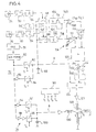
- a device is described below with reference to FIGS. 4 and 5 with which undesired displacements of the beam impact point in the x direction, which were measured in the manner described above, can be compensated for or corrected.
- the output signal from sensor 24 is fed to a pulse shaping circuit 50 (e.g. a Schmitt trigger circuit) which converts the output signal from sensor 24 into a rectangular pulse 52 (FIG. 5C) which has steep leading and trailing edges.
- the leading edge or trailing edge of the rectangular pulse 52 occur when the beam impact spot passes through the viewing area boundary 28a when passing through the measuring triangle and enters or exits the measuring area 28 of the sensor 24.
- a pulse generator circuit 54 which can be triggered by the rising leading edge is connected to the pulse shaping circuit 50 and is e.g. can consist of a monostable multivibrator and, when the leading edge of each pulse 52 occurs, supplies a rectangular pulse 56 (FIG. 5E) which is fed to an input of an AND circuit 58.
- the output of the second sensor 26 is connected to a pulse shaping circuit 60, which supplies rectangular output pulses 62 with steep leading and trailing edges to a pulse generator circuit 64 which, when the leading edge of each rectangular pulse 62 occurs, a short rectangular pulse 66 to an input of a second AND Circuit 68 provides.
- the second inputs of the AND circuits 58 and 68 will a trapezoidal x-deflection signal 70 is supplied by an x-deflection circuit 72, which causes the x-deflection during the measuring periods in which the measuring triangle 22 is passed.
- the y-deflection is effected by a y-deflection circuit 74 during each measurement period an SAE g ezahnsignal generated 76, as shown in Fig. 5B.
- the x deflection circuit 72 may, for example, contain an oscillator 78, the output signal of which is converted by a pulse shaping circuit 80 into a sequence of square-wave pulses having a constant area. These stretching pulses are fed directly to one input of a gate circuit 82 and to one input of a gate circuit 84 via an inverter 86. The outputs of the gate circuits 82 and 84 are connected to one another and to an integrating capacitor 88. Gate 82 is gated by a gate pulse T 1 (FIG. 5G) during the rising edge 70 of the trapezoidal x deflection signal each measurement period so that it then passes the pulses from pulse shaping circuit 80 to integrating capacitor 88 where it produces the rising edge 70a can be integrated. The frequency of the output signal of the oscillator 78 is so high that the rising edge 70a, which in practice is a step function, is sufficiently smooth.
- the gate circuit 84 is switched through during the falling edge 70b of the trapezoidal x deflection signal 70 by a gate pulse T 2 . Since the pulses then passed through the gate circuit 84 due to the inverter 86 have the opposite polarity as the pulses from the gate circuit 82, the charge on the capacitor 88 is reduced again to zero, producing the falling edge 70b.
- the gate pulses T, and T 2 are generated by a clock 90, which can be constructed in a known manner.
- the y deflection circuit 74 is constructed similarly. It contains a gate circuit 92, to which the pulses from the pulse shaping circuit 80 are fed via an inverter 94, and a second gate circuit 96, to which the pulses are fed from the pulse shaping circuit 80 via a non-inverting amplifier circuit 98, which has twice the amplification level as the inverter 94.
- the outputs of the gate circuits 92 and 96 are connected to one another and to an integrating capacitor 100.
- the gate circuit 92 is switched through by the clock generator 90 during the falling edges 76 and 76c of the sawtooth signal 76 by gate pulses T 3 , while the gate circuit 96 is switched through by the clock generator 90 during the rising edge 76b of the sawtooth by a gate pulse T 4 . Since the pulses that are passed through the gate circuit 96 are twice as large as the pulses from the gate circuit 92 because of the difference in the amplification levels of the inverter 94 and the amplifier circuit 98, the rising edge 76b is steeper than the edges 76a and 76c.
- the polarity and amplitude of the control pulses T1 to T 4 shown in FIGS. 5G and 5H are intended to symbolize the polarity and amplitude of the pulses which are passed through by the relevant gate circuits 82, 84, 92 and 96 during the duration of the relevant pulses.
- the x deflection signal which arises at the integrating capacitor 88, is fed to the signal input of the gate circuits 58 and 68.
- the pulses supplied by the pulse generator circuits 54 and 64 to the control inputs of these gate circuits thus cut out a pulse (for example the pulse 102 in FIG. 5F) from the edge 70a of the trapezoidal x deflection signal 70, the amplitude of which corresponds to the amplitude of the trapezoidal x deflection signal 70 corresponds to the moment of occurrence of the leading edge of the pulse 52 or 62.
- Holding circuits 104, 106 are connected to the outputs of the gate circuits 58 and 68, respectively, which hold the sampled signal amplitude until the next sampling during the next measuring period.
- a signal which corresponds to S R is thus available at the output of the holding circuit 104, while a signal which corresponds to S B is available at the output of the holding circuit 106.
- both S R and S B are equal to S 0 .
- differential amplifiers 108 and 112 Two subtraction circuits shown as differential amplifiers 108 and 112 are used to form the differences required to implement equation (4).
- the two inputs of the differential amplifier 108 are connected to the outputs of the holding circuits 104 and 106.
- One input of differential amplifier 112 is connected to the output of holding circuit 106, while at the other input there is a bias voltage corresponding to S o , which is generated by a preferably adjustable bias voltage source 114.
- the output of the differential amplifier 108 is connected to an input of a summing circuit 120 via an amplifier 116, the gain of which is adjustable so that the factor tg ⁇ tg ⁇ can be set.
- the output of the differential amplifier 112 is connected to the other input of the summing circuit.
- a signal is therefore available at the output of summing circuit 120 which is proportional to ⁇ x.
- This signal is preferably fed via an amplitude setting element 122, for example a potentiometer (or a controllable amplifier) to a further summing circuit 124, in which it is combined with the x deflection signal from the integrating capacitor 188.
- the combined x deflection signal is fed via a power amplifier 126 x deflection coils 128 to the electron beam welding machine, which is not shown in any more detail and which can be designed in a known manner.
- SR and SB are both equal to S 0 , so that the output signals of differential amplifiers 108 and 112 are also equal to zero.
- the conditions at the target position of the beam impact point are shown in the left side of FIG. 5.
- the right side of FIG. 5 applies to conditions as have been explained with reference to the lower part of FIG. 3.
- the pulses 56 and 66 no longer occur in the middle of the rising edge 70a of the trapezoidal x-deflection signal (time t 4 ), but at times t ' 4 and t " 4 , as represented by the pulses 56' and 66 ' Accordingly, the output pulses 102 'and 102 "of the gate circuits 58 and 68 also have an amplitude which deviates from the target value (pulse 102; corresponding to SO ), so that a correction signal is produced which compensates for the deviation ⁇ x. Otherwise, the operation of the device should be apparent from the above explanation in connection with FIGS. 4 and 5.
- only one side flank 22a of the measuring triangle was used for measuring purposes and therefore only detected any deviation of the surface of one workpiece part 10a. If desired, however, the other side flank 22b of the measuring triangle can also be used for measuring purposes and the position of the surface of the workpiece part 10b can also be detected. It is only necessary to use additional pulse generator circuits corresponding to the pulse generator circuits 54 and 64, which are responsive to the trailing edge of the pulses 52 and 62, respectively. The gate pulses generated by these pulse generator circuits then control further gate circuits corresponding to the gate circuits 58 and 68, the output signals of which are then processed accordingly to form a further signal ⁇ x ', as was described above for the generation of the signal ⁇ x.
- an average value can be formed and this average value can then be supplied to the adder circuit 124 as a correction signal.
- An additional or alternative use of the signal ⁇ x ' is to form a signal corresponding to the absolute value of the difference (Ax - Ax') and to generate a warning signal if this difference exceeds a predetermined value.
- two differential amplifiers for positive or negative differences
- a connected threshold circuit the outputs of which are connected to an alarm circuit via an OR gate
- a correction signal ⁇ x corresponding to the average height level of the surfaces of the workpiece parts 10a and 10b can also be generated by implementing the following equation:
- An additional pulse generator circuit 54 ' is connected to the output of the pulse shaping circuit 50 and responds to the trailing edges of the output pulses 52 of the pulse shaping circuit 50 .
- the output pulses 56 '(FIG. 5E) of the pulse generator circuit 54' control an additional gate circuit 58 ', the signal input of which is connected to the integrating capacitor 88 and the signal output of which is connected to a holding circuit 104'.
- the output signal of the hold circuit 104 ' is fed together with the output signal of the hold circuit 104 to an averaging circuit 140, in which the output signals of the hold circuits 104 and 104' are summed and adjusted in amplitude so that the Dif Output amplifier 108 supplied output signal of the circuit arrangement 140 corresponds to the right bracket expression in equation (5).
- undesired displacements of the beam impact point in the y direction (or more precisely, displacements of the central beam direction in the y direction at the location of the workpiece surface), which are caused by magnetic interference fields with an x component, can also be detected.
- a further measuring field boundary 150 (FIG. 1) which is parallel to the welding direction (x) and at a distance from the central beam direction 30 (ie at a distance from the joint 12) and in the example according to FIG. 1 is perpendicular to the workpiece surface.
- the measuring field limit 150 can be determined by a separate sensor 152, e.g. an X-ray sensor, but is preferably formed by a sharp lateral measuring field boundary (34d 'in FIGS. 13a and 13c) of a single sensor 27' (FIG. 9), as can be explained with reference to FIGS. 9 to 14.
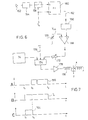
- the circuit arrangement according to FIG. 4 can be supplemented by a circuit arrangement of the type shown in FIG. 6 when the additional sensor is used.
- the additional sensor can be, for example, an X-ray sensor 152 corresponding to sensors 24 and 26.
- a pulse shaping circuit 154 is connected to its output, which corresponds to pulse shaping circuit 50 or 60 and generates an output signal 156 (FIG. 7A) with steep edges.
- the output of the pulse shaping circuit 154 is connected via a gate circuit 158 to a reset input R of a flip-flop 160.
- the pulse-shaped control signal T 4 (FIG. 5H) is fed to the control input of the gate circuit 158, so that the gate circuit 158 is transparent, while the beam is the base side 22c of the measuring triangle 22 (Fig. 1) passes through.
- the control signal T 4 is simultaneously fed to a set input S of the flip-flop 160, which is set by the rising leading edge of the control signal T 4 and, when set, generates an output signal 164 (FIG. 7C) on an output line 162.
- the flip-flop is reset at a variable time t 5 by the leading edge of the shaped output signal 156 of the sensor 152, so that the duration of the output signal 164 of the flip-flop corresponds to the time that the beam has during the measuring period from the beginning of the base side 22c to the limit of the field of view 150 needed. This route is designated y in FIG. 1.
- the output signal 164 of the flip-flop 160 is integrated by an integrating circuit 166 and converted into a DC voltage of corresponding magnitude, which is fed to an input of a subtracting circuit shown as a differential amplifier 168.
- a voltage Vy o is supplied to the other input of the subtracting circuit from an adjustable bias voltage source 170.
- the voltage Vy o corresponds to the setpoint value of y 1 , that is to say the value which the distance between the beginning of the base side 22c and the line of sight limit 150 has if there is no interference magnetic field.
- An error voltage thus occurs at the output of the differential amplifier 168, which represents the magnitudes and signs of the displacements of the beam impingement point in the y direction caused by the interference magnetic field.
- This error voltage is fed via an amplitude adjuster 172 to a summing circuit 174, in which the error voltage is combined with the y deflection voltage 76 (FIG. 5B) or a frond voltage deflecting the beam between the measuring periods in the y direction.
- the frond voltage can be a sinusoidal voltage of, for example, a few 100 or 1000 Hz frequency and is supplied via a line 176.
- the exit of the summing scarf device is coupled to the y deflection coils 130 via a corresponding power amplifier 178.
- the described exemplary embodiments can of course be modified in a wide variety of ways, and the measures explained can in part also be used individually or in other combinations than those described above.
- the height of the measuring triangle calculated in the x direction can be, for example, 6 mm, and the length of the base side 22c can also be 6 mm.
- a measuring period that is to say the time between t 0 and t 3 (FIG. 5A), can be a few milliseconds, for example 2 milliseconds, and the measuring periods can follow one another with a repetition frequency of, for example, 1 Hz to a few hundred Hertz.
- the beam voltage and the beam current are advantageously the same during the measurement period as during welding or machining.
- the speed at which the beam is deflected during the measuring period is expediently so high that there is no undesirable influence on the workpiece.
- An X-ray sensor usually contains a type of counter tube or a scintillation crystal in combination with a photomultiplier. Such sensors deliver an output signal consisting of short pulses, the frequency (number per unit of time) of which depends on the intensity of the X-rays.
- the accuracy of the determination of the point in time at which the beam passes through the sensor measuring range limits depends on a number of parameters, including the beam current strength and the beam focusing (ie the beam diameter on the workpiece surface).
- the rise time of the frequency function for the pulses delivered by the sensor changes, for example in the event of changes in the radiation intensity and thus also the point in time at which a counter value threshold (that is to say a certain number of pulses per unit of time or pulse frequency) is reached by which the exceeding of the measuring range limit is defined.
- the slope of the rise or fall in the frequency function of the sensor output signal decreases, and statistical shifts in time of these rise and fall processes can occur, and thus the point in time at which the count value, which is considered to have exceeded the measuring range limit, is reached , more uncertain. Since the position of this point in time at a reference point in time (for example the beginning of the measuring period) determines the size of the measuring signal, which is then used for position correction, the accuracy of this correction depends on the exactness of the determination of the relevant point in time.
- the preferred embodiment of the invention which is described below with reference to FIGS. 8 to 15, allows a more precise determination of the point in time which is relevant for the derivation of the correction signal, so that a better position correction is possible.
- only a single sensor is required in this embodiment.
- the averaged time therefore allows a much more precise determination of any deviations in the desired distance between the focal spot and because of the spatially fixed, known relationship between the measuring path and the wire feed point (usually both the sensor and the feed mechanism for the additional wire are attached to a common holder with the beam generation system) Wire feed point and thus a correspondingly more precise correction.
- the height of the surface of the workpiece does not change so that the sensor measuring range does not shift on the workpiece surface. But if two sheets to be welded do not match in thickness or if the surfaces are not completely flat, the surface of one sheet is at a different height than that of the other. If the axis of the field of view of the sensor is at an angle to the workpiece surface, then according to the rules of radiation optics, the two parts of the measuring range on the surfaces of the two metal sheets on both sides of the weld joint move relative to each other, so that the area boundaries at the joint no longer merge, but parallel to each other are offset.
- An expedient embodiment of the invention therefore consists in forming a time average from all four different times at which the beam on the measuring path exceeds the measuring range limits, on the basis of which the control signal is then derived and the correction is carried out.
- the position of the measuring range can be determined relatively easily keep constant with respect to the wire immersion point.
- the measuring path is based on the current focal spot, which does not necessarily coincide with the central axis of the jet gun, but must be regulated to compensate for external influences on the desired processing area, the position of the measuring path to the measuring range limits depends on such external influences, and the times when they are exceeded
- the measuring range limits by the beam passing through the measuring path therefore contain information about the positional deviations between the focal spot and the beam gun axis or the machine parts and positions which are related to it in a known spatial relationship, such as the immersion point of the wire supplied as additional material for the weld joint. If the feed direction is again referred to as the x direction, then deviations ⁇ x from the desired distance between the focal spot and the wire immersion point can be determined and corrected in the manner described above.
- the preferred method also allows more precise measurement of deviations of the focal spot from the cannon axis in the y direction running transversely to the feed direction, that is to say lateral emigration ⁇ y of the focal spot with respect to the cannon axis.
- the beam is passed through a measuring path section which crosses the two other measuring range limits running parallel to the weld joint, and the mean value is formed from these two crossing times, which coincides with the y position of the gun axis in the case of symmetrical or undisturbed conditions. This is not the case, then the focal spot has migrated out of this y target position due to interference magnetic fields, ie its y position no longer coincides with that of the cannon or machine axis and must be returned to this target position by an appropriate correction.
- FIG. 8 the welding of two sheets 14 'and 16' with the aid of an electron beam, which is supplied by a beam generation system or a beam gun 30 ', is shown as an illustrative example of a machining process.
- the position of the jet gun is adjusted so that the jet 10 'strikes the weld joint 12' between the sheets 14 'and 16' and generates such a high energy density that a focal spot 18 'is created in which the material melts.
- additional material is carried out e.g. in the form of a wire 20 'from a nozzle 21' behind the focal spot 18 '.
- the focal spot forms the processing point and travels in the feed direction x along the joint 12 '.
- the finished weld is designated 24 '.
- the beam 10 ' can be deflected - conveniently with the help of suitable magnetic fields. Such a case is shown in dash-dot lines in the drawing. Without deflection, the beam 10 "would strike the sheet metal surface next to the joint 12 '. With the help of two magnets 26' and 28 ', magnetic fields of such strength are generated that the beam hits the joint 12' exactly and produces the focal spot 18". Such a focal spot correction may also be necessary if the joint 12 'is straight, if the beam is deflected from its normal course by interference fields or the jet gun 30 'is not exactly positioned.
- the beam 10 ' which in this illustration coincides with the central axis 31' of the beam gun 30 'and runs in the z direction, ends up in the focal spot 18', which is shown here in the sheet metal surface 34 '.
- the beam 10 ' is deflected away from the focal spot 18' along a measuring path, the course of which will be explained in more detail, and then returns to the focal spot 18 'for further processing.
- a measuring area lying in front of the processing point (focal spot 18 ') with pairwise parallel boundary lines or area boundaries is defined on the surface 34', the two of which cross the joint 12 'extending area boundaries 34a' and 34b 'are shown in Fig. 2, while the other two area boundaries are in front of and behind the paper plane.
- the beam 10 'deflected in the x-direction now exceeds the limit 34a' upon entering the measuring range, whereupon the sensor 27 'detects an X-ray radiation resulting from the impingement of the beam 10' on the material surface 34 'and accordingly more pulses per Unit of time provides, i.e. changes the pulse rate from the rest value to a radiation detection value. Ver if the beam 10 'leaves the measuring range beyond the limit 34b', then the sensor 27 'no longer detects any radiation and the pulse rate falls back to the idle value.
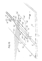
- FIG. 10 shows in perspective the relationships shown in FIG. 9 from the side.
- the three coordinate directions, x for the feed direction of the machining process, y for the transverse direction thereto and z for the perpendicular (direction of the beam gun axis 31 ') are also drawn in here.
- the beam 10 ' is deflected back and forth in the direction of the double arrow W, so that it detects the sheet metal edges on both sides for processing.
- the machining process is interrupted for such a short time that the welding process is not disturbed, and during the measuring period the beam 10 'is guided by a corresponding deflection along a measuring path 22' running through the measuring range, which starts from the focal spot 18 'and returns to it .
- all other parameters of the beam such as beam current and focusing, can advantageously be left constant.
- the output signal of the sensor 27 ' changes since it only perceives the background radiation as long as the beam 10' is outside the measuring range enclosed by the limits 34a 'to 34d'.
- the X-ray radiation which arises from points of the surface 34 ′ lying outside the measuring range when the beam 10 ′ strikes, is not perceived by the sensor. If, on the other hand, the beam impact point enters the measuring range, the X-ray radiation emanating from this point of impact reaches the sensor, which registers it by a sudden increase in its output pulse rate or the frequency function. As long as the beam 10 'strikes the material surface 34' within the measuring range with the limits 34a 'to 34d', the pulse rate of the sensor 27 'is higher than at beam impact points outside the measuring range.
- FIGS. 11 and 12 show the radiation intensity determined in the measuring range, and thus the size of the pulse rate J, over time. 11, when the focus is optimal, a relatively steep jump occurs when the beam, for example, exceeds the limit 34a 'of the measuring range at point 40a' and enters the measuring range. Since the I mpulsrate before and not absolute behind the jump con- s tant runs, the lower and upper mean value in the figure are entered.
- FIG. 11b shows a case with a larger beam diameter (defocusing), which leads to the change in the frequency function taking place more slowly than in FIG. 11a and the time range ⁇ t within which the evaluation circuit responds becomes correspondingly larger, so that the time of exceedance can be determined even less precisely, that is, it becomes less clear.
- a similar effect occurs when the beam current is too small, where the radiation intensity is not so strong and therefore the upper pulse rate is lower, so that the count value at which the evaluation circuit responds is more likely to occur in the flatter upper part of the frequency curve. This also makes the unsharpness range ⁇ t larger than in the case of FIG. 11a.
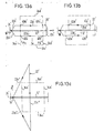
- Figure 13 illustrates only a few measurement path forms for the derivation of different control signals.
- the rectangular measuring area with the limits 34a 'to 34d' is traversed by a measuring path 22 'elongated in the feed direction x with the sections 22a' to 22e '.
- the measuring path crosses the measuring range limits 34a' and 34b 'at the points 40a' and 40b ', and in the course of this measuring path section the sensor output signal looks approximately as shown in FIG.
- the much more exact temporal mean value T M between the actual switching points in time at points 40a 'and 40b' is thus determined in the method described here defines the exact center of the measurement range along its boundaries 34c 'and 34d'.
- the unsharpness ranges ⁇ t E and ⁇ t A as well as the exact mean time T M are indicated for illustration.
- the situation can be determined the focal spot 18 'with respect to a machine reference point - such as the beam gun axis - in the x direction agree and regulate in a desired manner so that, for example, the distance between the focal spot 18 'and the immersion point of the additional wire 20' in the weld pool in the x-direction can be kept at an optimum value.
- a measuring path as shown in FIG. 13c as a triangle is suitable for determining the position in the y direction, one corner point of which lies in the focal spot 18 'and the opposite side 22c "of which the measuring range limits 34c' and 34d 'and between them the joint 12'
- the return and return sections of the measuring path are designated 22a "and 22e".
- a sensor output signal with a frequency curve of the type illustrated in FIG. 12 is again generated.
- an exact time value is again obtained for the derivation of a control signal for an Ay position control, for example for tracking the wire feed point with respect to the focal spot.
- FIG. 14 An arrangement is schematically illustrated in FIG. 14, with the aid of which the sensor signals can be evaluated to form the desired control signals.
- the sensor 27 On the basis of the X-rays detected in the measuring range, the sensor 27 'emits pulses, the frequency of which corresponds to the radiation intensity. These pulses are fed to a normalization circuit 41 ', in which the pulses are subjected to pulse shaping. It is also determined how many pulses occur per unit of time, and the corresponding count values are then stored in an intermediate memory 42 ', for example in the form of a RAM memory. The count values from the memory locations called are transferred from this buffer into a computer 43 '; a clock circuit 44 'can be used for this purpose, which switches the ON-LINE into the buffer 42' the entered count values can be saved in the computer cycle.
- the computer 43 ' is also connected to the beam deflection circuit 47' and, on the basis of the beam deflection signals determining the measurement path and the count values taken from the buffer 42 ', calculates the relevant points in time, including the mean value T M , and finally also calculates the desired control signals.
- the corresponding output signals of the computer 43 ' are converted with the aid of an information converter 45', which is usually also referred to as an interface, into control signals which, for example, the deflection coils 26 'and 28' (FIG. 8) 46 are fed to the respective actuator 'suitable, which then brings about the desired correction of the position of the beam gun or beam deflection.
- the current in the coils 26 'and 28' can be changed in opposite directions by the control signals so that there is a desired parallel displacement of the beam 10 ".
- the control signals can be supplied to a support controller (not shown) which adjusts the workpiece arrangement in y -Direction. So that the beam is centered with respect to the joint to be welded.
- the beam intensity is reduced during the measuring period.
- the same beam power is preferably used during the measuring period as during the actual machining process, e.g. of welding.
- the beam parameters that are optimal for the machining process are different from the beam parameters that are optimal for the measuring process.
- a typical example of this is the hardening of a workpiece with an electron beam, in which an electron beam of relatively large cross-section is used, which is unfavorable for measuring purposes, as was explained above with reference to FIGS. 11a and 11b. Even when welding, the beam is often not focused as sharply as possible on the workpiece surface.
- a stigmator 144 is now additionally provided, which is preferably arranged between the focusing lens 136 and a workpiece arrangement 146 to be welded.
- the stigmator 144 is connected to a stigmator control unit 148.
- the stigmator 144 and the associated control unit 148 are shown in more detail in FIG. 16.
- the stigmator is a device for generating a multipole field, e.g. a six-pole field.
- the stigmator 144 includes an annular magnetic core 150 with six internally projecting poles and three windings 152a, 152b and 152c.
- Each of the windings is connected to a circuit arrangement in the stigmator control unit 148, for the sake of simplicity only the circuit arrangement 148a for the winding 152a is shown in FIG. 16.
- This circuit arrangement contains two with their emitter-collector paths between a positive (+) and negative (-) terminal of an earth-symmetrical voltage source (not shown) and the one terminal of the winding 152a connected complementary transistors 154 and 156.
- the other terminal of this winding is grounded.
- the base electrodes of the two transistors are coupled to the output of a digital / analog converter 158, the input of which is connected to a corresponding output 159a of a microcomputer 160.
- the circuit arrangement 148a can be controlled by the computer in such a way that a current of the desired amplitude and polarity flows through the winding 152a.
- the windings 152b and 152c can be controlled in a corresponding manner, so that a desired multipole field can be generated in the region of the beam 110, which causes a stigmatic distortion of the beam cross section. This is shown in Fig. 17.
- the round one during welding (Exaggeratedly large) beam cross-section 110a is advantageously deformed during welding by the field of stigmator 144 so that, as shown at 110b, it has a fine tip 110c.
- the measuring range limit e.g. the measuring range limit 34b '(see also 13) so that the sensor only detects the part of the beam impact leak formed by the tip 110c. If the beam is then deflected in the direction of the arrow over the weld joint 12 ', the fine tip results in a very sharp and well-defined sensor output signal.
- FIG. 18 shows, it may also be expedient to "astigmatize" the beam such that it has a tip 110c 'running in the scanning direction (arrow).
- the measuring range limit 34d ' is exceeded, an output signal with a profile as shown in FIG. 19 is obtained.
- This course offers the possibility of using a threshold value circuit to generate a well-defined sensor signal, which occurs in FIG. 19, for example, at time t 0 .
- the computer 160 which is controlled by a clock generator, is programmed in such a way that it initiates a measuring process at specific time intervals or after a predetermined feed distance.
- the measuring program is read from a suitably programmed memory.
- Deflection power supply 142 is supplied with deflection signals from the computer, which result in the desired course of the measurement path (e.g. 22 'in FIG. 13).
- the computer also supplies digital control signals to the stigmator control unit 148, which are converted by the digital / analog converters 158 into control signals for the transistors 154, 156. As a result, the beam cross section is astigmatically distorted in the desired manner. Otherwise, the device works in the manner described above.
- the astigmatic deformation of the beam cross section described and the stigmator 144 which can be controlled as desired in the course of a processing and / or measuring process can also be used advantageously in charge beam processing devices other than those described above.
- a "fast" auxiliary focusing lens 144a is preferably arranged close behind the main focusing lens 136, which e.g. can contain an iron coreless coil with a correspondingly low self-induction, so that the field generated by the auxiliary focusing lens can be switched over quickly.
- the refractive power of the auxiliary focusing lens can e.g. to about 20% of the refractive power of the main focusing lens 136.
- the auxiliary focusing lens can be powered by a control circuit similar to control circuit 148a in FIG. 16.
- auxiliary focusing lens 144a which together with the unchanged field of the main focusing lens 136 ensures a sharp focusing of the electron beam 110 on the surface 146 of the workpiece (Fig. 15) and accordingly gives very accurate measured values.
- the control of the current of the auxiliary focusing lens can be done by the computer 160, as described above in connection with the stigmator.
Landscapes
- Engineering & Computer Science (AREA)
- Mechanical Engineering (AREA)
- Welding Or Cutting Using Electron Beams (AREA)
Applications Claiming Priority (4)
| Application Number | Priority Date | Filing Date | Title |
|---|---|---|---|
| DE2901148 | 1979-01-12 | ||
| DE19792901148 DE2901148A1 (de) | 1979-01-12 | 1979-01-12 | Verfahren und einrichtung zur positionsregelung eines ladungstraegerstrahls in einer ladungstraegerstrahl-werkzeugmaschine |
| DE19792937094 DE2937094A1 (de) | 1979-09-13 | 1979-09-13 | Verfahren zur regelung der position des strahlfleckes und/oder der zusatzmaterialzufuehrung bei einer maschine zur bearbeitung von werkstuecken mittels ladungstraegerstrahl |
| DE2937094 | 1979-09-13 |
Publications (2)
| Publication Number | Publication Date |
|---|---|
| EP0013573A1 true EP0013573A1 (fr) | 1980-07-23 |
| EP0013573B1 EP0013573B1 (fr) | 1982-07-28 |
Family
ID=25777374
Family Applications (1)
| Application Number | Title | Priority Date | Filing Date |
|---|---|---|---|
| EP80100128A Expired EP0013573B1 (fr) | 1979-01-12 | 1980-01-11 | Méthode et dispositif pour régler la position d'un rayon porteur de charges dans une machine-outil à rayon porteur de charges |
Country Status (3)
| Country | Link |
|---|---|
| US (1) | US4348576A (fr) |
| EP (1) | EP0013573B1 (fr) |
| DE (1) | DE3060679D1 (fr) |
Cited By (1)
| Publication number | Priority date | Publication date | Assignee | Title |
|---|---|---|---|---|
| EP3972771B1 (fr) | 2019-05-21 | 2023-07-12 | Techmeta Engineering Sas | Appareil à souder par faisceau d'électrons |
Families Citing this family (59)
| Publication number | Priority date | Publication date | Assignee | Title |
|---|---|---|---|---|
| US4620288A (en) * | 1983-10-26 | 1986-10-28 | American Semiconductor Equipment Technologies | Data handling system for a pattern generator |
| FR2559695B1 (fr) * | 1984-02-20 | 1995-04-21 | Mitsubishi Electric Corp | Procede et appareil pour detecter et reguler la position d'un faisceau electronique de soudage |
| DE3442207A1 (de) * | 1984-11-19 | 1986-05-28 | Leybold-Heraeus GmbH, 5000 Köln | Elektronenstrahl-istpositionsgeber |
| DE4031545A1 (de) * | 1990-10-05 | 1992-04-09 | Hell Rudolf Dr Ing Gmbh | Verfahren und vorrichtung zur herstellung einer texturwalze |
| US5294771A (en) * | 1991-12-17 | 1994-03-15 | Rolls-Royce Plc | Electron beam welding |
| WO2001002128A1 (fr) * | 1999-07-05 | 2001-01-11 | Siemens Aktiengesellschaft | Procede permettant de decrire une trajectoire ideale predefinie a l'aide d'un faisceau de particules ou d'ondes et utilisation dudit procede |
| US20020063567A1 (en) * | 2000-11-30 | 2002-05-30 | Applied Materials, Inc. | Measurement device with remote adjustment of electron beam stigmation by using MOSFET ohmic properties and isolation devices |
| US8992816B2 (en) | 2008-01-03 | 2015-03-31 | Arcam Ab | Method and apparatus for producing three-dimensional objects |
| CN102470439B (zh) | 2009-07-15 | 2016-03-02 | 阿卡姆股份公司 | 制造三维物体的方法和设备 |
| AU2010295585B2 (en) | 2009-09-17 | 2015-10-08 | Sciaky, Inc. | Electron beam layer manufacturing |
| DE102009052392A1 (de) * | 2009-11-09 | 2011-12-15 | Carl Zeiss Nts Gmbh | SACP-Verfahren und teilchenoptisches System zur Ausführung eines solchen Verfahrens |
| WO2011123195A1 (fr) | 2010-03-31 | 2011-10-06 | Sciaky, Inc. | Méthodologie de balayage, et appareil et système pour la fabrication de couches par faisceau d'électrons au moyen d'un système de commande en boucle fermée |
| CN104023948B (zh) | 2011-12-28 | 2016-07-06 | 阿卡姆股份公司 | 用于在无模成形中检测缺陷的方法和设备 |
| WO2013098135A1 (fr) | 2011-12-28 | 2013-07-04 | Arcam Ab | Procédé et appareil pour fabriquer des articles tridimensionnels poreux |
| US9383460B2 (en) | 2012-05-14 | 2016-07-05 | Bwxt Nuclear Operations Group, Inc. | Beam imaging sensor |
| US9535100B2 (en) | 2012-05-14 | 2017-01-03 | Bwxt Nuclear Operations Group, Inc. | Beam imaging sensor and method for using same |
| US9561542B2 (en) | 2012-11-06 | 2017-02-07 | Arcam Ab | Powder pre-processing for additive manufacturing |
| DE112013006029B4 (de) | 2012-12-17 | 2025-05-08 | Arcam Ab | Verfahren und Vorrichtung zum Ausbilden eines dreidimensionalen Gegenstands |
| WO2014095200A1 (fr) | 2012-12-17 | 2014-06-26 | Arcam Ab | Procédé et appareil d'impression 3d |
| US9550207B2 (en) | 2013-04-18 | 2017-01-24 | Arcam Ab | Method and apparatus for additive manufacturing |
| US9676031B2 (en) | 2013-04-23 | 2017-06-13 | Arcam Ab | Method and apparatus for forming a three-dimensional article |
| US9415443B2 (en) | 2013-05-23 | 2016-08-16 | Arcam Ab | Method and apparatus for additive manufacturing |
| US9468973B2 (en) | 2013-06-28 | 2016-10-18 | Arcam Ab | Method and apparatus for additive manufacturing |
| US9505057B2 (en) | 2013-09-06 | 2016-11-29 | Arcam Ab | Powder distribution in additive manufacturing of three-dimensional articles |
| US9676033B2 (en) | 2013-09-20 | 2017-06-13 | Arcam Ab | Method for additive manufacturing |
| US10434572B2 (en) | 2013-12-19 | 2019-10-08 | Arcam Ab | Method for additive manufacturing |
| US9802253B2 (en) | 2013-12-16 | 2017-10-31 | Arcam Ab | Additive manufacturing of three-dimensional articles |
| US10130993B2 (en) | 2013-12-18 | 2018-11-20 | Arcam Ab | Additive manufacturing of three-dimensional articles |
| US9789563B2 (en) | 2013-12-20 | 2017-10-17 | Arcam Ab | Method for additive manufacturing |
| US9789541B2 (en) | 2014-03-07 | 2017-10-17 | Arcam Ab | Method for additive manufacturing of three-dimensional articles |
| US20150283613A1 (en) | 2014-04-02 | 2015-10-08 | Arcam Ab | Method for fusing a workpiece |
| US9310188B2 (en) * | 2014-08-20 | 2016-04-12 | Arcam Ab | Energy beam deflection speed verification |
| US10786865B2 (en) | 2014-12-15 | 2020-09-29 | Arcam Ab | Method for additive manufacturing |
| US9721755B2 (en) * | 2015-01-21 | 2017-08-01 | Arcam Ab | Method and device for characterizing an electron beam |
| US11014161B2 (en) | 2015-04-21 | 2021-05-25 | Arcam Ab | Method for additive manufacturing |
| US10807187B2 (en) | 2015-09-24 | 2020-10-20 | Arcam Ab | X-ray calibration standard object |
| US11571748B2 (en) | 2015-10-15 | 2023-02-07 | Arcam Ab | Method and apparatus for producing a three-dimensional article |
| US10525531B2 (en) | 2015-11-17 | 2020-01-07 | Arcam Ab | Additive manufacturing of three-dimensional articles |
| US10610930B2 (en) | 2015-11-18 | 2020-04-07 | Arcam Ab | Additive manufacturing of three-dimensional articles |
| US11247274B2 (en) | 2016-03-11 | 2022-02-15 | Arcam Ab | Method and apparatus for forming a three-dimensional article |
| US10549348B2 (en) | 2016-05-24 | 2020-02-04 | Arcam Ab | Method for additive manufacturing |
| US11325191B2 (en) | 2016-05-24 | 2022-05-10 | Arcam Ab | Method for additive manufacturing |
| US10525547B2 (en) | 2016-06-01 | 2020-01-07 | Arcam Ab | Additive manufacturing of three-dimensional articles |
| US10792757B2 (en) | 2016-10-25 | 2020-10-06 | Arcam Ab | Method and apparatus for additive manufacturing |
| US10987752B2 (en) | 2016-12-21 | 2021-04-27 | Arcam Ab | Additive manufacturing of three-dimensional articles |
| US11059123B2 (en) | 2017-04-28 | 2021-07-13 | Arcam Ab | Additive manufacturing of three-dimensional articles |
| US11532760B2 (en) | 2017-05-22 | 2022-12-20 | Howmedica Osteonics Corp. | Device for in-situ fabrication process monitoring and feedback control of an electron beam additive manufacturing process |
| US11292062B2 (en) | 2017-05-30 | 2022-04-05 | Arcam Ab | Method and device for producing three-dimensional objects |
| US11185926B2 (en) | 2017-09-29 | 2021-11-30 | Arcam Ab | Method and apparatus for additive manufacturing |
| US10529070B2 (en) | 2017-11-10 | 2020-01-07 | Arcam Ab | Method and apparatus for detecting electron beam source filament wear |
| US10821721B2 (en) | 2017-11-27 | 2020-11-03 | Arcam Ab | Method for analysing a build layer |
| US11072117B2 (en) | 2017-11-27 | 2021-07-27 | Arcam Ab | Platform device |
| US12350754B2 (en) | 2017-12-22 | 2025-07-08 | Arcam Ab | Electron beam source and the use of the same |
| US11517975B2 (en) | 2017-12-22 | 2022-12-06 | Arcam Ab | Enhanced electron beam generation |
| US11267051B2 (en) | 2018-02-27 | 2022-03-08 | Arcam Ab | Build tank for an additive manufacturing apparatus |
| US10800101B2 (en) | 2018-02-27 | 2020-10-13 | Arcam Ab | Compact build tank for an additive manufacturing apparatus |
| US11400519B2 (en) | 2018-03-29 | 2022-08-02 | Arcam Ab | Method and device for distributing powder material |
| EP3597333A1 (fr) * | 2018-07-19 | 2020-01-22 | Howmedica Osteonics Corporation | Système et procédé d'analyses de profils et de localisation de faisceau d'électrons en cours de procédé |
| RU2760201C9 (ru) * | 2020-12-30 | 2021-12-21 | федеральное государственное бюджетное образовательное учреждение высшего образования "Национальный исследовательский университет "МЭИ" (ФГБОУ ВО "НИУ "МЭИ") | Способ электронно-лучевой сварки с осцилляцией луча |
Citations (3)
| Publication number | Priority date | Publication date | Assignee | Title |
|---|---|---|---|---|
| CH476995A (fr) * | 1967-05-05 | 1969-08-15 | Onera (Off Nat Aerospatiale) | Procédé pour l'élaboration d'un matériau dans une enceinte par traitement thermique et installation pour sa mise en oeuvre |
| DE2122412A1 (en) * | 1970-03-24 | 1972-11-16 | Steigerwald Strahltechnik GmbH, 8000 München | Electron beam welded focusing device |
| US3775581A (en) * | 1971-06-23 | 1973-11-27 | Welding Research Inc | Seam tracking method |
Family Cites Families (9)
| Publication number | Priority date | Publication date | Assignee | Title |
|---|---|---|---|---|
| DE1615507U (de) | 1949-09-14 | 1950-11-02 | Ludwig Edel Fa | Glasschild. |
| DE903017C (de) * | 1951-01-31 | 1954-02-01 | Sueddeutsche Lab G M B H | Herstellung kleiner Kugeln aus hochschmelzbaren Materialien |
| DE1515197C3 (de) * | 1964-05-06 | 1974-08-15 | Steigerwald Strahltechnik Gmbh, 8000 Muenchen | Energiestrahl-Schweiß verfahren |
| GB1179161A (en) * | 1967-01-20 | 1970-01-28 | Vickers Ltd | Electron-Beam Welding. |
| GB1209034A (en) * | 1967-04-25 | 1970-10-14 | Welding Inst | Improvements relating to electron beam welding |
| DE2013950C3 (de) * | 1970-03-24 | 1975-02-20 | Steigerwald Strahltechnik Gmbh, 8000 Muenchen | Verfahren zum Verändern der Fokuslage längs der Strahlachse eines zum Schweißen dienenden Elektronenstrahls |
| DD110198A1 (fr) * | 1974-02-22 | 1974-12-12 | ||
| DE2821028A1 (de) | 1977-05-13 | 1978-11-16 | Steigerwald Strahltech | Verfahren und einrichtung zur strahlpositionsregelung in einem ladungstraegerstrahlgeraet |
| DD136355A1 (de) | 1978-04-14 | 1979-07-04 | Manfred Spiegler | Verfahren zum automatisierten elektronenstrahlschweissen mit zusatzwerkstoff |
-
1980
- 1980-01-08 US US06/110,555 patent/US4348576A/en not_active Expired - Lifetime
- 1980-01-11 DE DE8080100128T patent/DE3060679D1/de not_active Expired
- 1980-01-11 EP EP80100128A patent/EP0013573B1/fr not_active Expired
Patent Citations (4)
| Publication number | Priority date | Publication date | Assignee | Title |
|---|---|---|---|---|
| CH476995A (fr) * | 1967-05-05 | 1969-08-15 | Onera (Off Nat Aerospatiale) | Procédé pour l'élaboration d'un matériau dans une enceinte par traitement thermique et installation pour sa mise en oeuvre |
| GB1224233A (en) * | 1967-05-05 | 1971-03-03 | Onera (Off Nat Aerospatiale) | Improvements in and relating to heat treatment of materials |
| DE2122412A1 (en) * | 1970-03-24 | 1972-11-16 | Steigerwald Strahltechnik GmbH, 8000 München | Electron beam welded focusing device |
| US3775581A (en) * | 1971-06-23 | 1973-11-27 | Welding Research Inc | Seam tracking method |
Cited By (1)
| Publication number | Priority date | Publication date | Assignee | Title |
|---|---|---|---|---|
| EP3972771B1 (fr) | 2019-05-21 | 2023-07-12 | Techmeta Engineering Sas | Appareil à souder par faisceau d'électrons |
Also Published As
| Publication number | Publication date |
|---|---|
| DE3060679D1 (en) | 1982-09-16 |
| EP0013573B1 (fr) | 1982-07-28 |
| US4348576A (en) | 1982-09-07 |
Similar Documents
| Publication | Publication Date | Title |
|---|---|---|
| EP0013573B1 (fr) | Méthode et dispositif pour régler la position d'un rayon porteur de charges dans une machine-outil à rayon porteur de charges | |
| DE2458370C2 (de) | Energiestrahl-Gravierverfahren und Einrichtung zu seiner Durchführung | |
| DE2631250C3 (de) | Verfahren und Vorrichtung zur selbsttätigen Führung eines Schweißbrenners auf Schweißfugenmitte | |
| DE3443803C2 (de) | Spurfehlersignalerzeuger | |
| DE3505857C2 (fr) | ||
| DE3875539T2 (de) | Automatisches lichtbogen-schweissverfahren. | |
| EP2830813B1 (fr) | Procédé de détermination des paramètres d'un faisceau de porteurs de charge, dispositif de mesure et dispositif à faisceau de porteurs de charge avec un tel dispositif de mesure | |
| DE2821028A1 (de) | Verfahren und einrichtung zur strahlpositionsregelung in einem ladungstraegerstrahlgeraet | |
| CH623497A5 (fr) | ||
| DE1225775B (de) | Verfahren und Einrichtung zur Bearbeitung eines Werkstueckes mittels eines Ladungstraegerstrahles | |
| DE2153695B2 (de) | Verfahren und Einrichtung zur Re gelung des Strahlstroms in technischen Ladungstragerstrahlgeraten, insb Elek tronenstrahl Materialbearbeitungsma schinen | |
| DE1125096B (de) | Verfahren zum Herstellen einer Schweisszone gewuenschter Querschnittsform beim Ladungstraegerstrahl-Schweissen | |
| EP0098244A1 (fr) | Procédé et dispositif de mise au point d'un rayon de lumière sur un objet | |
| WO2020007984A1 (fr) | Procédé et dispositif pour vérifier la position d'un foyer d'un rayon laser par rapport à une pièce ouvrée | |
| DE1765852C3 (de) | Vorrichtung zur Bearbeitung von Werkstoffen mit magnetisch fokussierten Ladungsträgerstrahlen | |
| DE2901148A1 (de) | Verfahren und einrichtung zur positionsregelung eines ladungstraegerstrahls in einer ladungstraegerstrahl-werkzeugmaschine | |
| DE2731142B2 (de) | Verfahren zur Feststellung der Lage eines Elektronenstrahls in bezug auf auf einem Objekt, angeordnete Ausrichtmarkierungen und Vorrichtung zur Durchführung des Verfahrens | |
| DE3718177C2 (fr) | ||
| DE2937646C2 (de) | Verfahren und Vorrichtung zum Nachführen des Elektronenstrahles beim Elektronenstrahlschweißen | |
| DE2937094A1 (de) | Verfahren zur regelung der position des strahlfleckes und/oder der zusatzmaterialzufuehrung bei einer maschine zur bearbeitung von werkstuecken mittels ladungstraegerstrahl | |
| EP0309930A1 (fr) | Procédé pour suivre un rayon d'électrons le long de l'interstice existant entre deux pièces à souder lors du soudage par rayon d'électrons | |
| DE3037230C2 (de) | Elektronenoptik für eine Elektronenstrahlschweißmaschine | |
| DE102018127986A1 (de) | Verfahren zum Betreiben einer Einrichtung zur additiven Herstellung eines dreidimensionalen Objekts | |
| DE2360829C3 (de) | Verfahren und Vorrichtung zur Messung des Brennfleckdurchmessers auf einem Werkstück bei einer ElektronenstrahlschweiBanlage | |
| DE69602149T2 (de) | Gerät zur lasergeführten Funkenerodierbearbeitung |
Legal Events
| Date | Code | Title | Description |
|---|---|---|---|
| PUAI | Public reference made under article 153(3) epc to a published international application that has entered the european phase |
Free format text: ORIGINAL CODE: 0009012 |
|
| AK | Designated contracting states |
Designated state(s): BE DE FR GB IT SE |
|
| 17P | Request for examination filed | ||
| RAP1 | Party data changed (applicant data changed or rights of an application transferred) |
Owner name: MESSER GRIESHEIM GMBH |
|
| RAP1 | Party data changed (applicant data changed or rights of an application transferred) |
Owner name: MESSER GRIESHEIM GMBH |
|
| GRAA | (expected) grant |
Free format text: ORIGINAL CODE: 0009210 |
|
| AK | Designated contracting states |
Designated state(s): BE DE FR GB IT SE |
|
| PG25 | Lapsed in a contracting state [announced via postgrant information from national office to epo] |
Ref country code: SE Effective date: 19820728 Ref country code: IT Free format text: LAPSE BECAUSE OF FAILURE TO SUBMIT A TRANSLATION OF THE DESCRIPTION OR TO PAY THE FEE WITHIN THE PRESCRIBED TIME-LIMIT;WARNING: LAPSES OF ITALIAN PATENTS WITH EFFECTIVE DATE BEFORE 2007 MAY HAVE OCCURRED AT ANY TIME BEFORE 2007. THE CORRECT EFFECTIVE DATE MAY BE DIFFERENT FROM THE ONE RECORDED. Effective date: 19820728 Ref country code: BE Effective date: 19820728 |
|
| REF | Corresponds to: |
Ref document number: 3060679 Country of ref document: DE Date of ref document: 19820916 |
|
| PGFP | Annual fee paid to national office [announced via postgrant information from national office to epo] |
Ref country code: FR Payment date: 19840116 Year of fee payment: 5 |
|
| PGFP | Annual fee paid to national office [announced via postgrant information from national office to epo] |
Ref country code: DE Payment date: 19850213 Year of fee payment: 6 |
|
| PG25 | Lapsed in a contracting state [announced via postgrant information from national office to epo] |
Ref country code: DE Effective date: 19861001 |
|
| GBPC | Gb: european patent ceased through non-payment of renewal fee | ||
| PG25 | Lapsed in a contracting state [announced via postgrant information from national office to epo] |
Ref country code: FR Free format text: LAPSE BECAUSE OF NON-PAYMENT OF DUE FEES Effective date: 19870930 |
|
| REG | Reference to a national code |
Ref country code: FR Ref legal event code: ST |
|
| PG25 | Lapsed in a contracting state [announced via postgrant information from national office to epo] |
Ref country code: GB Effective date: 19881118 |
|
| PLBE | No opposition filed within time limit |
Free format text: ORIGINAL CODE: 0009261 |
|
| STAA | Information on the status of an ep patent application or granted ep patent |
Free format text: STATUS: NO OPPOSITION FILED WITHIN TIME LIMIT |