EP0309930A1 - Procédé pour suivre un rayon d'électrons le long de l'interstice existant entre deux pièces à souder lors du soudage par rayon d'électrons - Google Patents
Procédé pour suivre un rayon d'électrons le long de l'interstice existant entre deux pièces à souder lors du soudage par rayon d'électrons Download PDFInfo
- Publication number
- EP0309930A1 EP0309930A1 EP88115642A EP88115642A EP0309930A1 EP 0309930 A1 EP0309930 A1 EP 0309930A1 EP 88115642 A EP88115642 A EP 88115642A EP 88115642 A EP88115642 A EP 88115642A EP 0309930 A1 EP0309930 A1 EP 0309930A1
- Authority
- EP
- European Patent Office
- Prior art keywords
- electron beam
- joint
- butt joint
- time
- workpieces
- Prior art date
- Legal status (The legal status is an assumption and is not a legal conclusion. Google has not performed a legal analysis and makes no representation as to the accuracy of the status listed.)
- Granted
Links
Images



Classifications
-
- B—PERFORMING OPERATIONS; TRANSPORTING
- B23—MACHINE TOOLS; METAL-WORKING NOT OTHERWISE PROVIDED FOR
- B23K—SOLDERING OR UNSOLDERING; WELDING; CLADDING OR PLATING BY SOLDERING OR WELDING; CUTTING BY APPLYING HEAT LOCALLY, e.g. FLAME CUTTING; WORKING BY LASER BEAM
- B23K15/00—Electron-beam welding or cutting
- B23K15/0013—Positioning or observing workpieces, e.g. with respect to the impact; Aligning, aiming or focusing electron beams
Definitions
- the invention relates to a method for guiding an electron beam along the butt joint of two workpieces to be welded during electron beam welding, this electron beam being controllable by a deflection system and a detector device being provided which distinguishes the beams emanating from the butt joint from the rays emanating from the workpieces go out, and which has a connecting device which carries out a scanning of the workpieces while crossing the butt joint at least once.
- the beam can be adjusted in such a way that the position of the workpieces to be welded is determined and the position of the weld joint is measured at one point before each welding process. The measured value is then saved and used as the setpoint for the further welding process.
- the effect is usually exploited that the backscattering behavior of the electrons in the area of the butt joint differs from the backscattering behavior on flat workpieces.
- the current of the backscattered electrons one can determine whether the electron beam is hitting the joint or a workpiece.
- a method for automatic welding of a workpiece by means of a focused electron beam along a welding gap is already known, in which the backscattered electrons are measured before the actual welding process and used to obtain several position data of the weld joint (DE-PS 30 43 635).
- the workpiece is moved along its welding gap past the point of impact of the electron beam, this point of impact being positionally corrected using the stored position data.
- the various position data are formed by averaging a large number of individual measurements in which a scanning beam is moved within a predetermined distance along the weld joint and at different points across the weld joint.
- the large number of individual measurements is intended to reduce the influence of any incorrect measurements.
- Such incorrect measurements occur again and again in practice because the gap pulses required for determining the position data are absent, e.g. B. because a gap is too narrow or false "gap pulses" are generated by interference pulses.
- a disadvantage of this known method is that it can only be used if the error rate in the individual measurements does not exceed a certain level.
- the difference between the number of individual measurements and the number of gap signals occurring is formed within a predetermined distance, and the difference value is compared with a predetermined tolerance value, an error signal being emitted when the tolerance value is exceeded. There is no correlation of measurement errors.
- Methods are also known for tracking an electron beam along the butt joint of two parts to be welded during electron beam welding, in which the electron beam is guided across the butt joint several times and in which the position of the butt joint is determined during the transverse movement by collecting reflected electrons (DE- OS 22 20 335, DE-PS 29 37 646).
- a position signal is generated in each scanning cycle, which is buffered and controls the further operation of a deflection unit, with several measurement values being obtained from the joint pulses within each scanning cycle and averaging being carried out.
- a disadvantage of all these methods is that they require averaging of several measurement data.
- an electron beam welding method in which a pulse is generated when the electron beam crossing the butt joint passes zero, while another pulse is generated when the electron beam and the butt joint cross (DD-PS 110 198). If the two pulses occur at different times, the beam deflection or the position of the workpiece is changed.
- the disadvantage here is that a pulse must always come and the absence of pulses is not taken into account.
- the invention has for its object to quickly and reliably detect the position of a weld joint at one or more points along this weld joint either continuously during the welding process or even outside the welding process, even if there are statistical and / or systematic errors.
- This object is achieved in that the time (z. B. t2 - t1) of a joint pulse when scanning the workpieces in a first direction and the maximum of the deflection signal is compared with the time (t3 - t2) between the maximum of the deflection signal and The occurrence of a joint pulse during the subsequent scanning of the workpieces in the opposite direction, and that if the difference exceeds a predetermined value, the determined joint position, which corresponds to the time (t4 - t3), is rejected and a new scanning process begins, while then, If the difference between the setpoint and actual value does not exceed the specified value, the determined joint position is used to control the electron beam.
- the invention thus relates to a method for tracking an electron beam along the butt joint of two workpieces to be welded during electron beam welding.
- This procedure consists of a basic procedure and an additional procedure.
- the time (t4 - t3) is measured, which elapses from the impact of a joint scanning beam on the butt joint of two workpieces to be welded to one another until the deflection curve shape crosses zero.
- the electron beam is readjusted via a deflection system.
- the additional method prevents interference pulses from falsifying the measurement instead of a joint pulse.
- FIG. 1 shows the principle of an arrangement known per se, in which the method according to the invention can be used.
- This arrangement has two workpieces 1, 2 to be welded to one another, which abut each other along a butt joint 3.
- a strongly focused electron beam 4 is directed onto the butt joint 3, while the workpieces 1, 2 are continuously moved along the main direction of the butt joint indicated by an arrow 5.
- the electron beam 4 originates from a stationary device and the workpieces 1, 2 are moved
- the invention can also be used in arrangements in which the workpieces 1, 2 remain stationary and the electron beam 4 is moved.
- a deflection system 6 with two x deflection coils 7 and two y deflection coils 8 is provided to influence the direction of the electron beam 4.
- the y deflection coils 8 cause deflections of the electron beam 4 transversely to the butt joint 3, while the x deflection coils 7, with appropriate electrical control, cause deflections of the electron beam 4 parallel to the main direction of the butt joint 3 indicated by arrow 5.
- the electron beam 4 passes through the opening of a metallic collecting plate 9, which is arranged at a distance above the workpieces 1, 2 parallel to the workpiece surface and is connected to earth potential via an electrical resistor 10. If the electron beam 4 strikes the smooth or almost smooth surfaces of the workpieces 1, 2, then 1, 2 electrons are reflected by these workpieces. These reflected electrons are then collected by the collecting plate 9 and diverted to earth via the resistor 10. In this way, a constant voltage drop occurs across the resistor 10. If the electron beam 4 strikes the butt joint 3, the electrons are at least partially absorbed by the joint, as a result of which the backscattered current is reduced. When the electron beam 4 hits the butt joint 3, fewer electrons are guided onto the collecting plate 9. The current through resistor 10 is reduced and, accordingly, the voltage drop across resistor 10.
- the electron beam striking the workpieces 1, 2 or the butt joint 3 not only causes electrons to be backscattered, but also causes X-rays 11. These X-rays 11 arise because the electrons are slowed down as they pass through matter. Since the braking of the electron beams in the butt joint 3 is less than in the workpieces 1, 2, more X-rays 11 are emitted when the electron beam 4 strikes the workpieces 1, 2. These X-rays or a part of these X-rays 11 can via an imaging system, for example an aperture 12 with a hole 13, on a position-sensitive sensor 14, for. B. a lateral diode.
- an evaluation circuit 15 which evaluates the currents of the position-sensitive sensor, it can be determined via the intensity of the incident X-ray radiation whether the X-ray beam 4 strikes the butt joint 3 or the workpieces 1, 2, and the exact position regardless of the intensity the point of impact.
- the device based on the detection of the X-rays 11 can be used as an alternative or in addition to the device which is based on the principle of collecting backscattered electrons.
- the voltage changes 18 and 18 ' are converted into normalized joint pulses 19 and 19', as shown in Fig. 2B in the diagram as U F.
- a measuring phase 17, 18, 18 'and a welding phase 16 the measuring phase 17, 18, 18' being connected to a waving of the electron beam 4 transversely to the butt joint 3.
- This waving is indicated in FIG. 1 by the reference number 20.
- the waving can also be carried out by an isolated measuring system, for example by a laser transceiver, which transmits a bundled light beam over the workpieces 1, 2 and the butt joint leads and recognizes the butt joint 3 on the basis of the received light signal.
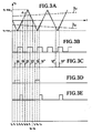
- FIG. 3A shows the y coordinate of the path s of a beam scanning the butt joint 3 over time.
- the y coordinate of the butt joint 3 is shown in dashed lines, once as a positive y coordinate 321 and once as a negative y coordinate 322. If the two workpieces 1, 2 are passed under the electron beam 4, the scanning beam is first deflected in the negative direction, where it meets the butt joint 322 at the time t 1. At the time t 1, a joint pulse 19 is consequently generated and detected (FIG. 3C). Since a maximum scanning amplitude s ymax- or s ymax + is provided symmetrically to an imaginary center line, which coincides with the t-axis in FIG.
- the scanning beam pivots over the butt joint 322 to the point s ymax- from where it is returned to the s ymax + position. In this way, he crosses the butt joint 322 again at time t3, whereupon another joint pulse 19 'is generated. Then the Ab cuts Taststrahl at time t4 the line of symmetry, which coincides with the time axis in FIG. 3A. Then he crosses the butt joint 321 at the time t5, whereupon a joint pulse 23 is formed, which is shown in dashed lines in Fig. 3C.
- the scanning beam reaches the maximum deflection s ymax + , from where it returns and cuts the butt joint 321 again, which results in the generation of a butt joint pulse 23 ', which is also shown in dashed lines in Fig. 3C.
- the butt joint pulses 23, 23 ' are shown in dashed lines because they relate to the butt joint 321, which is only accepted as a butt joint with a deviation in the opposite polarity. In reality there is only one butt joint, e.g. B. the butt joint 322, which is why only the butt joint pulses belonging to this butt joint 322 are shown with solid lines.
- the scanning beam After the scanning beam has crossed the butt joint 321, it arrives at the time t8 to the plane of symmetry and cuts the butt joint 322 at time t,, which results in the butt joint pulse 19 ⁇ .
- the scanning beam At the time t10 the scanning beam has reached its maximum negative y-deflection s ymax- and returns from there to the axis of symmetry, again crossing the butt joint 322 at the time t11 generating a butt joint pulse 19 ⁇ .
- the rest of the process proceeds in a corresponding manner, which is why its detailed description is dispensed with.
- the method according to the invention is based on the fact that pulses can only be joint pulses if they occur symmetrically or almost symmetrically (joint inclination) to the turning points of the deflection function at times t2 and t6. With the help of the joint impulses received, the following steps are carried out:
- a time counter is set in motion, which counts the time that passes until the point s ymax- at the time t 2 . From time t2 to time t3, that is until the occurrence of the next joint pulse 19 ', the time counter counts backwards, so that when the butt joint 3 is parallel to the line of symmetry, the total amount of the time counter must be zero.
- the butt joint 322 does not run parallel to the line of symmetry, which is identical to the time axis t, but it is inclined to this. Since the time t2 - t1 is greater than the time t3 - t2, there is an excess in the time counter, which indicates the inclination of the butt joint 322.
- the maximum permissible inclination is set by means of a device 44 (not shown in FIG. 3) with which the measuring windows can be determined. It is now assumed that the joint pulses are simulated by interference pulses that occur before or after the actual target time of the joint pulses. In order to eliminate these interference pulses, it is assumed according to the invention that a joint pulse that occurs before the appearance of the joint pulse 19 or 19 'can actually only be an interference pulse.
- FIG. 4 shows at 24 how the scanning beam runs transversely to the butt joint when it is timed in the manner shown in FIG. 3A. It can be seen here that it only moves along the y-axis, ie its x-deflection is zero. Such an x-deflection is not required absolutely, if the scanning beam is stationary and the workpieces are moved under it in the x-direction. In this way, he automatically scans the butt joint 3 at different positions. Due to the movement of the workpieces, the continuous transverse deflection 24 changes into a band.
- the scanning beam In order to be able to determine the course of the butt joint 3 during welding, it is possible for the scanning beam to make one or more jumps in the x direction, as is indicated by the double arrows 25 to 27. Instead of discrete jumps, zigzag movements of the scanning beam are also possible, as shown, for example, in FIG. 4 of DE-PS 29 37 646, or circular movements, as identified by reference number 28. Zigzag movements occur when moving in the x and y directions at the same time.
- the control of the x and y coordinates of the scanning beam takes place in a manner known per se. If the scanning beam is realized by the electron beam 4 itself, the deflection system 6 can be controlled accordingly. If the scanning beam is independent of the electron beam, it depends on the type of beam which deflection is used.
- FIG. 5 shows a block diagram which illustrates the processing of the butt joint pulses.
- This block diagram shows an essentially known arrangement in the right part, while the addition according to the invention is shown in the left part.
- the known arrangement has a triangular generator 30 which is connected to a control logic 31, the output of which leads to an AND gate 32 and which also controls a measurement counter 33 which is connected to the output of the AND gate 32.
- the measuring counter 33 is followed by a measured value memory 34, the output of which leads to a converter 35.
- the output signals of the measured value memory 34 and of the measuring counter 33 are sent to a comparator 42 which compares the last correct measured value stored with the new measured value.
- An oscillator 36 clocks the AND gate 32.
- the measured value memory 34 is not provided in known arrangements.
- the supplement according to the invention contains control logic 37, which controls an AND gate 39 via a line 38, which is clocked by the oscillator 36.
- the output of the AND gate 39 leads to a control counter 40, which is also connected to the control logic 37 via a line 41.
- a connection leads from the control counter 40 to a comparator 43, which in turn leads to a device 44 with which the measurement windows can be determined.
- the output of the comparator 43 is also connected to the input of the control logic 37.
- a connection line 45 leads from the control logic 37 to the measured value memory 34.
- the control logic 31 is connected to the control logic 37 via a line 46. Joint control signals 31 and control logic 37 are supplied with joint pulses via a line 47.
- the joint pulses are given to a counter 48, the number of pulses t0 within the time. . . t8 or t2. . . t10 counts. If the number exceeds a certain value, the determined position is discarded and a new scan is carried out.
- This counter 48 exchanges information in both directions with the control logic 37.
- the triangle generator 30 is closely connected to the control logic 31, which also generates further pulses in addition to the pulses shown in FIG. 3B. For example, it gives the measuring counter 33 a polarity signal and a storage pulse, while it generates the measuring window according to FIG. 3E and feeds the AND gate 32 to the pulse curve according to FIG. 3B with the joint pulse 19 '. Within these measurement windows, the pulses of the oscillator 36 are counted into the measurement counter 33 by the AND gate 32.
- the converter 35 converts the counter reading of the measuring counter 33 into an analog voltage corresponding to the gap deviation.
- the control according to the invention is carried out with the joint pulses and with various signals which are sent from the control logic 31 via the line 46 to the control logic 37.
- This control logic 37 generates a gate signal, which is sent to the AND gate 39 via the line 38 and which is shown in FIG. 3D. It also generates a polarity and advance signal which is fed to the control counter 40 via line 41. During the gate signal, the pulses of the oscillator 36 are counted in the control counter 40 and compared with the measurement window which is defined in the device 44. Depending on the result of this comparison, a memory pulse is generated in the control logic 37 and fed to the measured value memory 34 via the line 45.
Landscapes
- Engineering & Computer Science (AREA)
- Mechanical Engineering (AREA)
- Welding Or Cutting Using Electron Beams (AREA)
Applications Claiming Priority (2)
| Application Number | Priority Date | Filing Date | Title |
|---|---|---|---|
| DE3732880 | 1987-09-30 | ||
| DE3732880A DE3732880C1 (de) | 1987-09-30 | 1987-09-30 | Verfahren zum Nachfuehren eines Elektronenstrahls entlang der Stossfuge zweier zu verschweissender Werkstuecke beim Elektronenstrahlschweissen |
Publications (2)
| Publication Number | Publication Date |
|---|---|
| EP0309930A1 true EP0309930A1 (fr) | 1989-04-05 |
| EP0309930B1 EP0309930B1 (fr) | 1992-07-29 |
Family
ID=6337173
Family Applications (1)
| Application Number | Title | Priority Date | Filing Date |
|---|---|---|---|
| EP88115642A Expired - Lifetime EP0309930B1 (fr) | 1987-09-30 | 1988-09-23 | Procédé pour suivre un rayon d'électrons le long de l'interstice existant entre deux pièces à souder lors du soudage par rayon d'électrons |
Country Status (2)
| Country | Link |
|---|---|
| EP (1) | EP0309930B1 (fr) |
| DE (2) | DE3732880C1 (fr) |
Cited By (1)
| Publication number | Priority date | Publication date | Assignee | Title |
|---|---|---|---|---|
| DE102009050521A1 (de) * | 2009-10-23 | 2011-04-28 | Pro-Beam Ag & Co. Kgaa | Thermisches Materialbearbeitungsverfahren |
Families Citing this family (5)
| Publication number | Priority date | Publication date | Assignee | Title |
|---|---|---|---|---|
| DE4142144A1 (de) * | 1991-12-20 | 1993-06-24 | Messer Griesheim Gmbh | Verfahren zum erfassen von elektronenstrahlmaschinen-zustaenden |
| AU2010295585B2 (en) | 2009-09-17 | 2015-10-08 | Sciaky, Inc. | Electron beam layer manufacturing |
| EP2555902B1 (fr) | 2010-03-31 | 2018-04-25 | Sciaky Inc. | Méthode de balayage de trame pour la construction de pièces couche par couche à l'aide d'un faisceau d'electrons controlé en boucle fermée |
| DE102020213858A1 (de) * | 2020-11-04 | 2022-05-05 | Robert Bosch Gesellschaft mit beschränkter Haftung | Vorrichtung und Verfahren zum Bestimmen einer Lage einer Strahltaille eines fokussierten Strahls relativ zu einer Referenzoberfläche |
| DE102024207322A1 (de) * | 2024-08-01 | 2026-02-05 | Pro-Beam Gmbh & Co. Kgaa | Verfahren und Vorrichtung zum Fügen eines ersten Bauteils und eines zweiten Bauteils mittels eines Elektronenstrahls |
Citations (3)
| Publication number | Priority date | Publication date | Assignee | Title |
|---|---|---|---|---|
| DE2937646B1 (de) * | 1979-09-18 | 1980-12-11 | Eichhorn Friedrich Prof Dr Ing | Verfahren und Vorrichtung zum Nachfuehren des Elektronenstrahles beim Elektronenstrahlschweissen |
| DE2937094A1 (de) * | 1979-09-13 | 1981-04-02 | Steigerwald Strahltechnik Gmbh, 8031 Puchheim | Verfahren zur regelung der position des strahlfleckes und/oder der zusatzmaterialzufuehrung bei einer maschine zur bearbeitung von werkstuecken mittels ladungstraegerstrahl |
| DE3043635C1 (de) * | 1980-11-19 | 1987-05-07 | Institut für Kerntechnik und Energiewandlung e.V., 7000 Stuttgart | Verfahren und Anordnung zum automatischen Elektronenstrahlschweißen |
Family Cites Families (6)
| Publication number | Priority date | Publication date | Assignee | Title |
|---|---|---|---|---|
| DE1299498B (de) * | 1964-07-24 | 1969-07-17 | Steigerwald Strahltech | Vorrichtung zur UEberwachung des Strahlauftreffbereichs in Korpuskularstrahl-Bearbeitungsgeraeten |
| GB1179161A (en) * | 1967-01-20 | 1970-01-28 | Vickers Ltd | Electron-Beam Welding. |
| FR1542746A (fr) * | 1967-09-07 | 1968-10-18 | Combustible Nucleaire | Contrôle radiographique in situ de pièces soudées par bombardement électronique |
| US3775581A (en) * | 1971-06-23 | 1973-11-27 | Welding Research Inc | Seam tracking method |
| DE2354509C2 (de) * | 1973-10-31 | 1975-02-13 | Mahle Gmbh, 7000 Stuttgart | Anordnung zur Messung der Schweißnahttiefe beim Schweißen mit Ladungsträgerstrahlen |
| SE7805518L (sv) * | 1977-05-13 | 1978-11-14 | Steigerwald Strahltech | Forfarande och anordning for energibestralning |
-
1987
- 1987-09-30 DE DE3732880A patent/DE3732880C1/de not_active Expired
-
1988
- 1988-09-23 DE DE8888115642T patent/DE3873239D1/de not_active Expired - Fee Related
- 1988-09-23 EP EP88115642A patent/EP0309930B1/fr not_active Expired - Lifetime
Patent Citations (3)
| Publication number | Priority date | Publication date | Assignee | Title |
|---|---|---|---|---|
| DE2937094A1 (de) * | 1979-09-13 | 1981-04-02 | Steigerwald Strahltechnik Gmbh, 8031 Puchheim | Verfahren zur regelung der position des strahlfleckes und/oder der zusatzmaterialzufuehrung bei einer maschine zur bearbeitung von werkstuecken mittels ladungstraegerstrahl |
| DE2937646B1 (de) * | 1979-09-18 | 1980-12-11 | Eichhorn Friedrich Prof Dr Ing | Verfahren und Vorrichtung zum Nachfuehren des Elektronenstrahles beim Elektronenstrahlschweissen |
| DE3043635C1 (de) * | 1980-11-19 | 1987-05-07 | Institut für Kerntechnik und Energiewandlung e.V., 7000 Stuttgart | Verfahren und Anordnung zum automatischen Elektronenstrahlschweißen |
Cited By (3)
| Publication number | Priority date | Publication date | Assignee | Title |
|---|---|---|---|---|
| DE102009050521A1 (de) * | 2009-10-23 | 2011-04-28 | Pro-Beam Ag & Co. Kgaa | Thermisches Materialbearbeitungsverfahren |
| US8314358B2 (en) | 2009-10-23 | 2012-11-20 | Pro-Beam Ag & Co. Kgaa | Thermal material-processing method |
| DE102009050521B4 (de) | 2009-10-23 | 2023-02-16 | Pro-Beam Ag & Co. Kgaa | Thermisches Materialbearbeitungsverfahren |
Also Published As
| Publication number | Publication date |
|---|---|
| DE3732880C1 (de) | 1988-12-08 |
| EP0309930B1 (fr) | 1992-07-29 |
| DE3873239D1 (de) | 1992-09-03 |
Similar Documents
| Publication | Publication Date | Title |
|---|---|---|
| EP0770445B1 (fr) | Méthode de contrôle et de positionnement d'un faisceau ou d'un jet pour l'usinage d'une pièce | |
| EP0367924B1 (fr) | Procédé et dispositif pour déterminer la position d'un joint d'une soudure pour le soudage à laser | |
| DE102008049821B4 (de) | Abstandssensor und Verfahren zur Ermittlung eines Abstands und/oder von Abstandsschwankungen zwischen einem Bearbeitungslaser und einem Werkstück | |
| EP0013573B1 (fr) | Méthode et dispositif pour régler la position d'un rayon porteur de charges dans une machine-outil à rayon porteur de charges | |
| DE3833022C2 (fr) | ||
| DE4405376C1 (de) | Verfahren zum Erfassen von Objekten in einem Überwachungsbereich | |
| DE102015015330B4 (de) | Bearbeitungsvorrichtung und Verfahren zum Überwachen eines mit einer Bearbeitungsvorrichtung ausgeführten Bearbeitungsprozesses | |
| DE2602001C3 (de) | Vorrichtung zur Überprüfung einer bearbeiteten Oberfläche eines Werkstucks | |
| DE19917509C1 (de) | Optoelektronische Vorrichtung | |
| DE3822143A1 (de) | Verschiebungssensor mit optischer abtastung | |
| DE102017126867A1 (de) | Laserbearbeitungssystem und Verfahren zur Laserbearbeitung | |
| EP2886239A1 (fr) | Procédé et dispositif de surveillance et de régulation de la trajectoire d'usinage lors d'un processus d'assemblage à laser | |
| EP0254772A2 (fr) | Méthode de la détermination du diamètre des roues de véhicules sur rail et dispositif pour cela | |
| CH621275A5 (fr) | ||
| DE4039318A1 (de) | Einrichtung zur erfassung der hoehenlage einer laserbearbeitungsvorrichtung bezueglich eines werkstuecks | |
| EP0309930B1 (fr) | Procédé pour suivre un rayon d'électrons le long de l'interstice existant entre deux pièces à souder lors du soudage par rayon d'électrons | |
| CH623497A5 (fr) | ||
| DE2258158C3 (de) | Schaltungsanordnung für einen Detektor zum Feststellen von Fehlern in einer bewegten Materialbahn | |
| DE3516664A1 (de) | Optische anordnung zur passiven entfernungsbestimmung | |
| DE2646838C3 (de) | Vorrichtung zum automatischen Regeln von Systemen auf die Mitte von Schweißspalten, Schweißfugen oder Schweißnah tuberhohungen | |
| DE3043635C1 (de) | Verfahren und Anordnung zum automatischen Elektronenstrahlschweißen | |
| EP4306998A1 (fr) | Capteur optique | |
| DE3203720C2 (de) | Gerät zur Erkennung von auf Gegenständen angebrachten, optischen Codemarken | |
| DE2937646C2 (de) | Verfahren und Vorrichtung zum Nachführen des Elektronenstrahles beim Elektronenstrahlschweißen | |
| EP0617256B1 (fr) | Procédé pour déterminer le diamètre d'une circonférence d'une zone ou d'un train de zones et dispositif le mettant en oeuvre |
Legal Events
| Date | Code | Title | Description |
|---|---|---|---|
| PUAI | Public reference made under article 153(3) epc to a published international application that has entered the european phase |
Free format text: ORIGINAL CODE: 0009012 |
|
| AK | Designated contracting states |
Kind code of ref document: A1 Designated state(s): CH DE FR GB IT LI |
|
| 17P | Request for examination filed |
Effective date: 19890408 |
|
| 17Q | First examination report despatched |
Effective date: 19900907 |
|
| RAP1 | Party data changed (applicant data changed or rights of an application transferred) |
Owner name: PTR PRAEZISIONSTECHNIK GMBH |
|
| GRAA | (expected) grant |
Free format text: ORIGINAL CODE: 0009210 |
|
| AK | Designated contracting states |
Kind code of ref document: B1 Designated state(s): CH DE FR GB LI |
|
| PG25 | Lapsed in a contracting state [announced via postgrant information from national office to epo] |
Ref country code: FR Effective date: 19920729 |
|
| REF | Corresponds to: |
Ref document number: 3873239 Country of ref document: DE Date of ref document: 19920903 |
|
| PG25 | Lapsed in a contracting state [announced via postgrant information from national office to epo] |
Ref country code: CH Effective date: 19920930 Ref country code: LI Effective date: 19920930 |
|
| GBT | Gb: translation of ep patent filed (gb section 77(6)(a)/1977) | ||
| EN | Fr: translation not filed | ||
| REG | Reference to a national code |
Ref country code: CH Ref legal event code: PL |
|
| PLBE | No opposition filed within time limit |
Free format text: ORIGINAL CODE: 0009261 |
|
| STAA | Information on the status of an ep patent application or granted ep patent |
Free format text: STATUS: NO OPPOSITION FILED WITHIN TIME LIMIT |
|
| 26N | No opposition filed | ||
| REG | Reference to a national code |
Ref country code: GB Ref legal event code: IF02 |
|
| PGFP | Annual fee paid to national office [announced via postgrant information from national office to epo] |
Ref country code: GB Payment date: 20050913 Year of fee payment: 18 |
|
| PGFP | Annual fee paid to national office [announced via postgrant information from national office to epo] |
Ref country code: DE Payment date: 20050929 Year of fee payment: 18 |
|
| PG25 | Lapsed in a contracting state [announced via postgrant information from national office to epo] |
Ref country code: DE Free format text: LAPSE BECAUSE OF NON-PAYMENT OF DUE FEES Effective date: 20070403 |
|
| GBPC | Gb: european patent ceased through non-payment of renewal fee |
Effective date: 20060923 |
|
| PG25 | Lapsed in a contracting state [announced via postgrant information from national office to epo] |
Ref country code: GB Free format text: LAPSE BECAUSE OF NON-PAYMENT OF DUE FEES Effective date: 20060923 |