EP0013701A1 - Procédé et dispositif de préservation de pièces non symétrique en rotation par application d'un revêtement suivant le procédé par immersion - Google Patents
Procédé et dispositif de préservation de pièces non symétrique en rotation par application d'un revêtement suivant le procédé par immersion Download PDFInfo
- Publication number
- EP0013701A1 EP0013701A1 EP19790104376 EP79104376A EP0013701A1 EP 0013701 A1 EP0013701 A1 EP 0013701A1 EP 19790104376 EP19790104376 EP 19790104376 EP 79104376 A EP79104376 A EP 79104376A EP 0013701 A1 EP0013701 A1 EP 0013701A1
- Authority
- EP
- European Patent Office
- Prior art keywords
- workpiece
- coating
- rotation
- axis
- coating agent
- Prior art date
- Legal status (The legal status is an assumption and is not a legal conclusion. Google has not performed a legal analysis and makes no representation as to the accuracy of the status listed.)
- Ceased
Links
- 239000011248 coating agent Substances 0.000 title claims abstract description 72
- 238000000576 coating method Methods 0.000 title claims abstract description 41
- 238000000034 method Methods 0.000 title claims abstract description 36
- 238000007598 dipping method Methods 0.000 title abstract description 7
- 230000033001 locomotion Effects 0.000 claims description 24
- 238000007654 immersion Methods 0.000 claims description 10
- 230000001133 acceleration Effects 0.000 claims description 3
- 238000013519 translation Methods 0.000 claims description 2
- 230000000977 initiatory effect Effects 0.000 claims 1
- 210000003903 pelvic floor Anatomy 0.000 claims 1
- 230000014616 translation Effects 0.000 claims 1
- 239000000463 material Substances 0.000 description 3
- 230000004323 axial length Effects 0.000 description 2
- 239000003795 chemical substances by application Substances 0.000 description 2
- 238000005246 galvanizing Methods 0.000 description 2
- 239000013040 bath agent Substances 0.000 description 1
- 239000003086 colorant Substances 0.000 description 1
- 238000005260 corrosion Methods 0.000 description 1
- 230000007797 corrosion Effects 0.000 description 1
- 230000018109 developmental process Effects 0.000 description 1
- 238000001035 drying Methods 0.000 description 1
- 238000004070 electrodeposition Methods 0.000 description 1
- 230000001788 irregular Effects 0.000 description 1
- 239000007788 liquid Substances 0.000 description 1
- 210000000056 organ Anatomy 0.000 description 1
- 239000003973 paint Substances 0.000 description 1
- 230000002028 premature Effects 0.000 description 1
- 239000003755 preservative agent Substances 0.000 description 1
- 230000003014 reinforcing effect Effects 0.000 description 1
- 230000000630 rising effect Effects 0.000 description 1
- 238000005245 sintering Methods 0.000 description 1
Images

Classifications
-
- B—PERFORMING OPERATIONS; TRANSPORTING
- B05—SPRAYING OR ATOMISING IN GENERAL; APPLYING FLUENT MATERIALS TO SURFACES, IN GENERAL
- B05C—APPARATUS FOR APPLYING FLUENT MATERIALS TO SURFACES, IN GENERAL
- B05C3/00—Apparatus in which the work is brought into contact with a bulk quantity of liquid or other fluent material
- B05C3/02—Apparatus in which the work is brought into contact with a bulk quantity of liquid or other fluent material the work being immersed in the liquid or other fluent material
- B05C3/04—Apparatus in which the work is brought into contact with a bulk quantity of liquid or other fluent material the work being immersed in the liquid or other fluent material with special provision for agitating the work or the liquid or other fluent material
-
- B—PERFORMING OPERATIONS; TRANSPORTING
- B05—SPRAYING OR ATOMISING IN GENERAL; APPLYING FLUENT MATERIALS TO SURFACES, IN GENERAL
- B05C—APPARATUS FOR APPLYING FLUENT MATERIALS TO SURFACES, IN GENERAL
- B05C3/00—Apparatus in which the work is brought into contact with a bulk quantity of liquid or other fluent material
- B05C3/02—Apparatus in which the work is brought into contact with a bulk quantity of liquid or other fluent material the work being immersed in the liquid or other fluent material
- B05C3/09—Apparatus in which the work is brought into contact with a bulk quantity of liquid or other fluent material the work being immersed in the liquid or other fluent material for treating separate articles
- B05C3/10—Apparatus in which the work is brought into contact with a bulk quantity of liquid or other fluent material the work being immersed in the liquid or other fluent material for treating separate articles the articles being moved through the liquid or other fluent material
Definitions
- the invention relates to a method for preserving workpieces by applying a coating using the rotary dipping method, in which the workpiece is immersed at most up to its axis of rotation in the coating agent.
- the invention also relates to at least one device for carrying out the rotary dipping process, the workpiece being held directly by organs of the device during the coating process.
- GB-PS 644 16Q a method and a device is disclosed, which has a rotary dipping method to the content.
- a larger object in the form of a vehicle body is partially immersed in a coating agent bath and rotated about a horizontal axis.
- the body is coated in particular with coating agent on the outside.
- the disadvantage here is that the applied coating agent coating is uneven and accordingly has too thin spots that cause premature corrosion or the like, and on the other hand has too thick spots that result in an uneconomical consumption of coating agent, apart from that of that the coating structure having irregular structures looks ugly.
- the rotational speed of the workpiece to be coated must be set so that all areas of the workpiece are coated, the speed is selected so that it is lower than that at which the coating agent runs down the workpiece.
- a correspondingly long coating time must be accepted.
- the object of the invention is to provide a method for preserving workpieces by applying a coating using the rotary dipping method, with which a uniform coating application can be achieved in a simple manner with simultaneously reduced consumption of coating agent.
- the object is also to create a device with which such a method can be carried out.
- the angular velocity of the rotational movement of the workpiece is controlled as a function of the angle of immersion, the angle of exchange being formed between the level surface of the coating agent in the immersion bath and the side surface of the workpiece to be coated, which is to be exchanged.
- a device for carrying out the improved method is that the device mentioned in the introduction is provided according to the invention with a control unit, which with the operating parameters relevant to the coating process, such as angular acceleration of the rotational and possibly the translational movement of the workpiece, type and temperature of the Coating agent, etc., is programmable so that the drive motor for the workpiece or for the conveying part of the device moving the workpiece through the immersion bath is controlled accordingly.
- a control unit which with the operating parameters relevant to the coating process, such as angular acceleration of the rotational and possibly the translational movement of the workpiece, type and temperature of the Coating agent, etc.
- the workpiece can be coated considerably more economically by means of the solution according to the invention and the achievement of a uniformly thick coating job, since the coating process runs optimally.
- the latter in particular, means that the coating agent consumption 'is considerably reduced, since a thick coating is partially to now avoided, and since the duration of the coating process is also reduced because the rotational speed of the temporarily higher workpiece to be coated. is considered the lowest speed required.
- the former is advantageously the case when an area of a workpiece side is emerging from the bath in order not to allow the inherent tendency to drip off of the coating agent just applied to be successful, in order to avoid the consequently unevenly thick coating. Overall, the coating process can therefore be carried out at considerably lower costs than before, since the consumption of coating agent in particular is greatly reduced.
- the procedure can also be such that the workpiece is adjusted about a further axis that runs horizontally and transversely to the axis of rotation. This ensures that places that are difficult to access inside or outside the workpiece, such as e.g. Niches, undercuts, corners, etc., can be coated in a simple manner, it being avoided that coating agent which is no longer required is left at these points because it can flow away more easily from it. This also reduces coating agent consumption.
- the device is developed, for example, in such a way that its gripping devices holding the workpiece are articulated on holders of the device.
- This makes it possible to adjust the workpiece about a horizontal axis that is horizontal to the axis of rotation, j M as can be done either on one side or in opposite directions and during the rotation of the workpiece is carried out frequently.
- the corners, undercuts, etc. are better reached with coating agent in this way and excess agent is removed again.
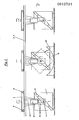
- the overhead conveyor for the container 1 consists of two parallel and horizontal support rails 2, 3, which stand on a support, not shown, and on which a carriage 4 can be moved over the four rollers 5 and 6 shown is, driven by the electric motors 7, 8.
- the carriage 4 With the carriage 4 are two vertical brackets 9, 10 with gimbal joints 11, 12 in connection, the axes of rotation of which form a common axis of rotation of the two gripping devices 13, 14.
- brackets 9, 10 can be adjusted up or down depending on the drive direction, in order to be able to raise and lower the container 1 relative to the stationary parts of the system.
- the brackets are made of vertical parts 16 out, which in turn are connected to the carriage 4.
- An electric motor 17 is connected to the axis of the gripping device 14 via a gear, while the axis of rotation of the other gripping device 13 is freely rotatable in the pivot bearing 11 there. In operation, this motor 17 will set the device 14 and thus also the container 1 during the coating and possibly also afterwards in rotation about the axis of rotation 18, which is also the longitudinal axis of the container, so that the lower part of the container through it Coating agent 19 is moved in the plunge pool 20.
- the container 1 is fastened to the conveyor in the position shown on the left in FIG. 1, in that the two double-armed devices 13, 14 are attached diagonally to the end faces of the container and the angled gripping elements 13a, 14a grasp the corresponding corners of the container.
- the gripping elements 13a, 14a should be telescopically adjustable, for example radially to the axis 18, and finally also be ascertainable in the working position.
- the gripping elements have a sufficient axial length in order not to slide off the container, in particular when it is tilted, as will become clear.
- the container By actuating the drive 15, the container is raised to a certain extent, whereupon the motors 7, 8 are adjusted in order to move the carriage 4 centrally over the plunge pool 20 into the middle position according to FIG.
- the container 1 By correspondingly opposite operation of the drive 15, the container 1 is lowered to such an extent that, according to the illustration, it just dips into the coating agent 19 with its lower horizontal side.
- the motor 17 is then set in order to set the container 1 in rotation about its longitudinal axis 18 in order to carry out the coating.
- this is important make sure that the distance between the center and longitudinal axis 18 extending over the pool 20 to the pool floor must be slightly larger than the longest possible radial extent of the workpiece or container 1 to be coated.
- the bottom of the immersion basin 20 is formed in the shape of a part of a circle in cross section, which means that in comparison to a basin with a rectangular cross section, correspondingly less coating agent needs to be filled in.
- the area of the container 1 emerging from the coating agent forms an angle ⁇ with the surface or the mirror of the coating agent 19, which changes periodically in the course of the rotational movement.
- this angle is between 0 ° and 90 ° depending on the advanced rotation. Due to these different exchange angles, the coating agent also runs back from the container walls into the immersion pool 20 at different speeds, which could give rise to uneven layer thicknesses if the coating agent has an unfavorable viscosity.
- the angular velocity of the rotational movement as a function of the angle ⁇ can be controlled in such a way that smaller angles are assigned a larger angular speed and larger angles a lower angular speed.
- the container is raised again via the drive 15, and expediently in such a way that any dripping of the coating agent which may still occur occurs over an edge which is later not visible on the finished product.
- this will be one of the lower edges of the stand area.
- the container 1 After lifting, the container 1 is then moved further with the conveyor, that is to say roughly into the position shown on the right in FIG. 1, and finally deposited there. After loosening the gripping elements 13, 14, the conveyor can return to its starting position or another position and pick up a new container there.
- the container rotates continuously or intermittently, and the direction of rotation can also be changed. If the brackets or their partial areas, which have the gripping devices, are not designed to be axially resilient, the axial length of the gripping elements 13a, 14a provides sufficient scope to accommodate the inclined position of the container enable.
- the inclination is effected by actuating one of the drives 15. If necessary, it can also be tilted in opposite directions. For this purpose, for example, the container end that was raised first is then lowered again without getting into the bathroom, and then the other is raised.
- the device can also be designed such that at least one of the brackets 9, 10 on the carriage 4 is designed to be pivotable about a horizontal transverse axis; or the portion of the same that carries the gripping device. Additionally or alternatively, at least one of the two gripping devices can also be axially resiliently mounted in the associated holder.
- the conveying unit can return to its starting position or can also assume a different position and pick up a new container there.
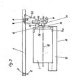
- a programmed control unit 21 is motion in dependence ⁇ from Austauchwinkel provided which controls the motor 17 with respect to its running time and speed, in particular in dependence on the following pre-programmed or even during the coating obtained data, - for controlling the angular velocity of rotation namely duration and angular velocity or angular acceleration of the rotational movement, shape and instantaneous position of the part to be coated as well as type and temperature of the coating agent.
- This on the Beschich tion process influencing factors and also the data that are required for a fully automatic sequence of the method could be stored on a data carrier. By simply replacing this data carrier, it is possible to switch to a different and pre-stored program without long setup and set-up times.
- the data for the respective rotational position of the container 1 can be scanned by means of a cam disk 22 which can be rotated with it, the scanned data obtained in this way being evaluated in the control unit 21 in order to initiate the control processes.
- a translatory movement in the direction of the axis of rotation 18 or also transversely thereto can be superimposed on the rotational movement of the container 1.
- a translation movement transverse to the axis of rotation would run perpendicular to the plane of the drawing in the exemplary embodiment according to FIG. 3.
- a prerequisite for carrying out such a longitudinal movement would of course be that the plunge pool 20 be given a different and adapted shape.
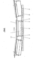
- FIG. 4 shows, on the other hand, a possibility for a translatory movement in the direction of the axis of rotation 18 First face into the coating bath.
- the container longitudinal axis and the bath surface form an angle ⁇ .
- the rotation process previously described in connection with the other exemplary embodiment begins.
- the travel movement and the rotation movement are now running at the same time, so that the container 1 rotates through the coating bath, wherein individually considered container parts perform a helical movement.
- the container 1 Due to the later rising course of the support rails 2, 3, the container 1 is moved out of the bath at the angle ⁇ .
- the rotational movement is stopped.
- the coating material begins to drip when the coating process has not yet been completed.
- the procedure can be such that a holder, e.g. the holder 9 is designed to be movable along the carrier of the carriage 4, so that this holder can assume the position shown in broken lines in FIG.
- the cardan joint axis 12 of the gripping device 14 is designed such that the latter can also be held in the desired inclined position.
- a holding member 23 comprising the axle body 12, which is one of the piston rod 24 Cylinder 25 is held.
- the cylinder 25 is arranged on the holder 10, which is stabilized by an additional reinforcing rib 26, and can be moved vertically. When this cylinder is actuated, the axis of rotation 18 ′ of the gripping device 14 is inclined.
- the above-mentioned inclination of the workpiece can also be carried out when the coating process is in full swing or when the workpiece is replaced. In addition to a good internal coating, this shortens the overall duration of the coating process.
- the coating agent to be applied in the normal or electrodeposition process which can be liquid or consist of a fluidized coating material, can be circulated in the immersion tank in order to achieve a uniform density of the respective coating agent.
Landscapes
- Coating Apparatus (AREA)
Applications Claiming Priority (2)
| Application Number | Priority Date | Filing Date | Title |
|---|---|---|---|
| DE2902352 | 1979-01-22 | ||
| DE19792902352 DE2902352C3 (de) | 1979-01-22 | 1979-01-22 | Verfahren und Vorrichtung zum Tauchbeschichten von Werkstücken, insbesondere von Containern |
Publications (1)
| Publication Number | Publication Date |
|---|---|
| EP0013701A1 true EP0013701A1 (fr) | 1980-08-06 |
Family
ID=6061130
Family Applications (1)
| Application Number | Title | Priority Date | Filing Date |
|---|---|---|---|
| EP19790104376 Ceased EP0013701A1 (fr) | 1979-01-22 | 1979-11-08 | Procédé et dispositif de préservation de pièces non symétrique en rotation par application d'un revêtement suivant le procédé par immersion |
Country Status (2)
| Country | Link |
|---|---|
| EP (1) | EP0013701A1 (fr) |
| DE (1) | DE2902352C3 (fr) |
Cited By (3)
| Publication number | Priority date | Publication date | Assignee | Title |
|---|---|---|---|---|
| GB2134012A (en) * | 1982-12-03 | 1984-08-08 | G O M International Limited | Coating plastic bottles |
| GB2202863A (en) * | 1987-02-28 | 1988-10-05 | Honda Motor Co Ltd | Automotive bodies surface treatment |
| CN113677823A (zh) * | 2019-02-20 | 2021-11-19 | 欧瑞康表面处理解决方案股份公司普费菲孔 | 用于在模块式涂覆设备中输送并移动基片的优化系统和方法 |
Families Citing this family (9)
| Publication number | Priority date | Publication date | Assignee | Title |
|---|---|---|---|---|
| DE4025062A1 (de) * | 1989-08-10 | 1991-02-14 | Vaillant Joh Gmbh & Co | Verfahren zum beschichten eines gegenstandes |
| US5863408A (en) * | 1995-06-06 | 1999-01-26 | Yamaha Hatsudoki Kabushiki Kaisha | Method and device for surface treatment |
| RU2150097C1 (ru) * | 1997-03-17 | 2000-05-27 | Извозчиков Илья Борисович | Устройство для обработки и пропитки гистологических образцов |
| DE10047968A1 (de) † | 2000-09-27 | 2002-04-18 | Flaekt Ab | Vorrichtung und Verfahren zur Oberflächenbehandlung von Werkstücken |
| DE20022321U1 (de) * | 2000-12-20 | 2001-06-07 | Eisenmann Maschinenbau KG (Komplementär: Eisenmann-Stiftung), 71032 Böblingen | Anlage zur Behandlung, insbesondere zum Lackieren, von Gegenständen, insbesondere von Fahrzeugkarosserien |
| DE102007063061A1 (de) * | 2007-12-28 | 2009-07-09 | Eisenmann Anlagenbau Gmbh & Co. Kg | Tauchbehandlungsanlage |
| DE202008017911U1 (de) | 2007-12-28 | 2010-10-21 | Eisenmann Anlagenbau Gmbh & Co. Kg | Tauchbehandlungsanlage |
| DE102008010400A1 (de) † | 2008-02-21 | 2009-10-29 | Eisenmann Anlagenbau Gmbh & Co. Kg | Hängebahnsystem und Tauchbehandlungsanlage mit einem solchen |
| CN116061362B (zh) * | 2022-12-27 | 2024-08-30 | 安徽和佳医疗用品科技有限公司 | Pvc医用手套生产用浸胶装置 |
Citations (12)
| Publication number | Priority date | Publication date | Assignee | Title |
|---|---|---|---|---|
| GB121233A (en) * | 1918-03-06 | 1918-12-12 | Thomas Tucker | Apparatus for Painting or Coating Metal Drums and like Vessels. |
| US2169816A (en) * | 1937-11-10 | 1939-08-15 | Continental Can Co | Method of coating can bodies |
| GB644169A (en) * | 1948-03-17 | 1950-10-04 | Carrier Engineering Co Ltd | Improvements in or relating to methods of and apparatus for cleaning, rustproofing, prime coating and spray painting sheet metal articles such as vehicle bodies |
| DE822062C (de) * | 1948-03-17 | 1951-11-22 | Carrier Engineering Co Ltd | Verfahren zum Befoerdern von aus Blech bestehenden Koerpern, vorzugs-weise Fahrzeugkoerpern, durch eine Anlage zum Reinigen, Verhueten des Rostens, Grundieren und Bespruehen mit einer Farbfluessigkeit und Vorrichtung zur Durchfuehrung des Verfahrens |
| FR1036676A (fr) * | 1951-02-14 | 1953-09-10 | Procédé et dispositif de peinture au trempé | |
| GB716790A (en) * | 1950-09-29 | 1954-10-13 | Rheem Mfg Co | Improved method and apparatus for processing surfaces of tubular containers and other articles |
| GB860955A (en) * | 1958-02-19 | 1961-02-15 | Hilary Page Sensible Toys Ltd | Method of and apparatus for the dip-coating of articles |
| US3028260A (en) * | 1958-09-05 | 1962-04-03 | Ball Brothers Co Inc | Method of coating containers |
| GB936147A (en) * | 1958-09-26 | 1963-09-04 | Saint Gobain | Improvements in or relating to a process and apparatus for coating articles |
| FR1421907A (fr) * | 1964-01-31 | 1965-12-17 | Carrier Engineering Co Ltd | Perfectionnements aux procédés de décapage et d'application d'anti-rouille, de couche d'impression, et de peinture sur des articles de tôle, tels que les carrosseries de véhicules |
| DE1922751A1 (de) * | 1969-05-03 | 1970-11-05 | Herberts & Co Gmbh Dr Kurt | Vorrichtung und Verfahren zum Beschichten von Gegenstaenden mit fluessigen Beschichtungsmitteln |
| DE2821192A1 (de) * | 1978-05-13 | 1979-11-15 | Ind Werke Transportsysteme Gmb | Verfahren und anlage zum konservieren von teilen durch auftragen einer beschichtung im tauchverfahren |
Family Cites Families (1)
| Publication number | Priority date | Publication date | Assignee | Title |
|---|---|---|---|---|
| GB1454495A (en) * | 1973-05-21 | 1976-11-03 | Lucas Electrical Ltd | Methods of coating articles |
-
1979
- 1979-01-22 DE DE19792902352 patent/DE2902352C3/de not_active Expired
- 1979-11-08 EP EP19790104376 patent/EP0013701A1/fr not_active Ceased
Patent Citations (12)
| Publication number | Priority date | Publication date | Assignee | Title |
|---|---|---|---|---|
| GB121233A (en) * | 1918-03-06 | 1918-12-12 | Thomas Tucker | Apparatus for Painting or Coating Metal Drums and like Vessels. |
| US2169816A (en) * | 1937-11-10 | 1939-08-15 | Continental Can Co | Method of coating can bodies |
| GB644169A (en) * | 1948-03-17 | 1950-10-04 | Carrier Engineering Co Ltd | Improvements in or relating to methods of and apparatus for cleaning, rustproofing, prime coating and spray painting sheet metal articles such as vehicle bodies |
| DE822062C (de) * | 1948-03-17 | 1951-11-22 | Carrier Engineering Co Ltd | Verfahren zum Befoerdern von aus Blech bestehenden Koerpern, vorzugs-weise Fahrzeugkoerpern, durch eine Anlage zum Reinigen, Verhueten des Rostens, Grundieren und Bespruehen mit einer Farbfluessigkeit und Vorrichtung zur Durchfuehrung des Verfahrens |
| GB716790A (en) * | 1950-09-29 | 1954-10-13 | Rheem Mfg Co | Improved method and apparatus for processing surfaces of tubular containers and other articles |
| FR1036676A (fr) * | 1951-02-14 | 1953-09-10 | Procédé et dispositif de peinture au trempé | |
| GB860955A (en) * | 1958-02-19 | 1961-02-15 | Hilary Page Sensible Toys Ltd | Method of and apparatus for the dip-coating of articles |
| US3028260A (en) * | 1958-09-05 | 1962-04-03 | Ball Brothers Co Inc | Method of coating containers |
| GB936147A (en) * | 1958-09-26 | 1963-09-04 | Saint Gobain | Improvements in or relating to a process and apparatus for coating articles |
| FR1421907A (fr) * | 1964-01-31 | 1965-12-17 | Carrier Engineering Co Ltd | Perfectionnements aux procédés de décapage et d'application d'anti-rouille, de couche d'impression, et de peinture sur des articles de tôle, tels que les carrosseries de véhicules |
| DE1922751A1 (de) * | 1969-05-03 | 1970-11-05 | Herberts & Co Gmbh Dr Kurt | Vorrichtung und Verfahren zum Beschichten von Gegenstaenden mit fluessigen Beschichtungsmitteln |
| DE2821192A1 (de) * | 1978-05-13 | 1979-11-15 | Ind Werke Transportsysteme Gmb | Verfahren und anlage zum konservieren von teilen durch auftragen einer beschichtung im tauchverfahren |
Cited By (4)
| Publication number | Priority date | Publication date | Assignee | Title |
|---|---|---|---|---|
| GB2134012A (en) * | 1982-12-03 | 1984-08-08 | G O M International Limited | Coating plastic bottles |
| GB2202863A (en) * | 1987-02-28 | 1988-10-05 | Honda Motor Co Ltd | Automotive bodies surface treatment |
| GB2202863B (en) * | 1987-02-28 | 1991-01-16 | Honda Motor Co Ltd | Automotive bodies surface treatment |
| CN113677823A (zh) * | 2019-02-20 | 2021-11-19 | 欧瑞康表面处理解决方案股份公司普费菲孔 | 用于在模块式涂覆设备中输送并移动基片的优化系统和方法 |
Also Published As
| Publication number | Publication date |
|---|---|
| DE2902352A1 (de) | 1980-07-24 |
| DE2902352C3 (de) | 1982-05-19 |
| DE2902352B2 (de) | 1980-12-04 |
Similar Documents
| Publication | Publication Date | Title |
|---|---|---|
| DE69000264T2 (de) | Vorrichtung zum markieren der oberflaeche von kaese- oder wurstwaren mittels laser. | |
| DE3715969C2 (fr) | ||
| DE4410477C1 (de) | Vorrichtung zur Oberflächenbehandlung von Fahrzeugkarosserien | |
| EP0013701A1 (fr) | Procédé et dispositif de préservation de pièces non symétrique en rotation par application d'un revêtement suivant le procédé par immersion | |
| DE10359280A1 (de) | Sprühbeschichtungsvorrichtung | |
| DE69012706T2 (de) | Herstellungsverfahren und Anlage zum Beschichten von Strukturteilen von Kraftfahrzeugen. | |
| EP0489292B1 (fr) | Procédé de glaçage des pièces en argile ou en porcelaine | |
| DE2800296A1 (de) | Vorrichtung zum fuellen von formen mit gefaerbten moertelmassen und zur bildung von zeichnungen auf der sichtbaren oberflaeche von ziegeln, kunststeinen o.dgl. mit hilfe von teilungstrennanordnungen | |
| DE2102458A1 (de) | Vorrichtung und Verfahren zum Behandeln, insbesondere Glavanisieren von Werkstücken | |
| DE20217416U1 (de) | Vorrichtung zum Beschichten eines Werkstücks mit Pulver | |
| EP1329264A2 (fr) | Méthode et appareil de traitement d'objets, en particulier pour le revêtement d'objets | |
| DE2307331A1 (de) | Vorrichtung zur entwicklung von flachdruckplatten | |
| DE3108549A1 (de) | Verfahren und vorrichtung zum glasieren keramischer hohlkoerper | |
| DE2821192C3 (de) | Verfahren und Anlage zum Tauchbeschichten von Teilen | |
| DE2443003C2 (de) | Verfahren zur Herstellung eines aus thermoplastischem oder thermohärtendem Kunststoff bestehenden Belags auf der inneren Oberfläche eines Hohlkörpers, sowie Vorrichtung zur Durchführung des Verfahrens | |
| DE19613927C1 (de) | Verfahren und Vorrichtung zum Beschichten von Kleinteilen | |
| DE2904176A1 (de) | Verfahren und vorrichtung zum konservieren von werkstuecken durch beschichten im tauchverfahren | |
| DE3915549C2 (fr) | ||
| EP0844054A1 (fr) | Dispositif d'émaillage avec table tournante | |
| WO1993010911A1 (fr) | Dispositif de conditionnement exterieur de vehicules a moteur | |
| DE102005008741B4 (de) | Verfahren und Vorrichtung zum selektiven Befüllen von regelmässig angeordneten wabenartigen Strukturen | |
| EP1171244B1 (fr) | Procede et dispositif pour la peinture de carrosseries de vehicules | |
| DE7406370U (de) | Schleifmaschine fuer die anbringung von dekorationsschliffen an hohl und pressglaesern | |
| DE102005037451B4 (de) | Verfahren und Vorrichtung zur Herstellung eines wenigstens zwei Komponenten enthaltenden stiftförmigen kosmetischen Produkts, wie Lippenpflegestift oder dergleichen | |
| CH687442A5 (de) | Einrichtung zum Reinigen von Gebinden. |
Legal Events
| Date | Code | Title | Description |
|---|---|---|---|
| PUAI | Public reference made under article 153(3) epc to a published international application that has entered the european phase |
Free format text: ORIGINAL CODE: 0009012 |
|
| AK | Designated contracting states |
Designated state(s): BE FR GB IT NL |
|
| 17P | Request for examination filed |
Effective date: 19810119 |
|
| RAP1 | Party data changed (applicant data changed or rights of an application transferred) |
Owner name: KRUSE, KARL-HERMANN |
|
| STAA | Information on the status of an ep patent application or granted ep patent |
Free format text: STATUS: THE APPLICATION HAS BEEN REFUSED |
|
| 18R | Application refused |
Effective date: 19830826 |