EP1329264A2 - Méthode et appareil de traitement d'objets, en particulier pour le revêtement d'objets - Google Patents
Méthode et appareil de traitement d'objets, en particulier pour le revêtement d'objets Download PDFInfo
- Publication number
- EP1329264A2 EP1329264A2 EP03009433A EP03009433A EP1329264A2 EP 1329264 A2 EP1329264 A2 EP 1329264A2 EP 03009433 A EP03009433 A EP 03009433A EP 03009433 A EP03009433 A EP 03009433A EP 1329264 A2 EP1329264 A2 EP 1329264A2
- Authority
- EP
- European Patent Office
- Prior art keywords
- coating
- workpiece
- roller
- workpieces
- transport device
- Prior art date
- Legal status (The legal status is an assumption and is not a legal conclusion. Google has not performed a legal analysis and makes no representation as to the accuracy of the status listed.)
- Withdrawn
Links
Images


Classifications
-
- B—PERFORMING OPERATIONS; TRANSPORTING
- B05—SPRAYING OR ATOMISING IN GENERAL; APPLYING FLUENT MATERIALS TO SURFACES, IN GENERAL
- B05C—APPARATUS FOR APPLYING FLUENT MATERIALS TO SURFACES, IN GENERAL
- B05C1/00—Apparatus in which liquid or other fluent material is applied to the surface of the work by contact with a member carrying the liquid or other fluent material, e.g. a porous member loaded with a liquid to be applied as a coating
- B05C1/04—Apparatus in which liquid or other fluent material is applied to the surface of the work by contact with a member carrying the liquid or other fluent material, e.g. a porous member loaded with a liquid to be applied as a coating for applying liquid or other fluent material to work of indefinite length
- B05C1/08—Apparatus in which liquid or other fluent material is applied to the surface of the work by contact with a member carrying the liquid or other fluent material, e.g. a porous member loaded with a liquid to be applied as a coating for applying liquid or other fluent material to work of indefinite length using a roller or other rotating member which contacts the work along a generating line
- B05C1/0826—Apparatus in which liquid or other fluent material is applied to the surface of the work by contact with a member carrying the liquid or other fluent material, e.g. a porous member loaded with a liquid to be applied as a coating for applying liquid or other fluent material to work of indefinite length using a roller or other rotating member which contacts the work along a generating line the work being a web or sheets
- B05C1/0834—Apparatus in which liquid or other fluent material is applied to the surface of the work by contact with a member carrying the liquid or other fluent material, e.g. a porous member loaded with a liquid to be applied as a coating for applying liquid or other fluent material to work of indefinite length using a roller or other rotating member which contacts the work along a generating line the work being a web or sheets the coating roller co-operating with other rollers, e.g. dosing, transfer rollers
-
- B—PERFORMING OPERATIONS; TRANSPORTING
- B05—SPRAYING OR ATOMISING IN GENERAL; APPLYING FLUENT MATERIALS TO SURFACES, IN GENERAL
- B05B—SPRAYING APPARATUS; ATOMISING APPARATUS; NOZZLES
- B05B13/00—Machines or plants for applying liquids or other fluent materials to surfaces of objects or other work by spraying, not covered by groups B05B1/00 - B05B11/00
- B05B13/02—Means for supporting work; Arrangement or mounting of spray heads; Adaptation or arrangement of means for feeding work
- B05B13/0221—Means for supporting work; Arrangement or mounting of spray heads; Adaptation or arrangement of means for feeding work characterised by the means for moving or conveying the objects or other work, e.g. conveyor belts
- B05B13/0242—Means for supporting work; Arrangement or mounting of spray heads; Adaptation or arrangement of means for feeding work characterised by the means for moving or conveying the objects or other work, e.g. conveyor belts the objects being individually presented to the spray heads by a rotating element, e.g. turntable
-
- B—PERFORMING OPERATIONS; TRANSPORTING
- B05—SPRAYING OR ATOMISING IN GENERAL; APPLYING FLUENT MATERIALS TO SURFACES, IN GENERAL
- B05C—APPARATUS FOR APPLYING FLUENT MATERIALS TO SURFACES, IN GENERAL
- B05C1/00—Apparatus in which liquid or other fluent material is applied to the surface of the work by contact with a member carrying the liquid or other fluent material, e.g. a porous member loaded with a liquid to be applied as a coating
- B05C1/02—Apparatus in which liquid or other fluent material is applied to the surface of the work by contact with a member carrying the liquid or other fluent material, e.g. a porous member loaded with a liquid to be applied as a coating for applying liquid or other fluent material to separate articles
- B05C1/022—Apparatus in which liquid or other fluent material is applied to the surface of the work by contact with a member carrying the liquid or other fluent material, e.g. a porous member loaded with a liquid to be applied as a coating for applying liquid or other fluent material to separate articles to the outer surface of hollow articles
-
- B—PERFORMING OPERATIONS; TRANSPORTING
- B05—SPRAYING OR ATOMISING IN GENERAL; APPLYING FLUENT MATERIALS TO SURFACES, IN GENERAL
- B05C—APPARATUS FOR APPLYING FLUENT MATERIALS TO SURFACES, IN GENERAL
- B05C1/00—Apparatus in which liquid or other fluent material is applied to the surface of the work by contact with a member carrying the liquid or other fluent material, e.g. a porous member loaded with a liquid to be applied as a coating
- B05C1/02—Apparatus in which liquid or other fluent material is applied to the surface of the work by contact with a member carrying the liquid or other fluent material, e.g. a porous member loaded with a liquid to be applied as a coating for applying liquid or other fluent material to separate articles
- B05C1/027—Apparatus in which liquid or other fluent material is applied to the surface of the work by contact with a member carrying the liquid or other fluent material, e.g. a porous member loaded with a liquid to be applied as a coating for applying liquid or other fluent material to separate articles only at particular parts of the articles
-
- B—PERFORMING OPERATIONS; TRANSPORTING
- B05—SPRAYING OR ATOMISING IN GENERAL; APPLYING FLUENT MATERIALS TO SURFACES, IN GENERAL
- B05C—APPARATUS FOR APPLYING FLUENT MATERIALS TO SURFACES, IN GENERAL
- B05C1/00—Apparatus in which liquid or other fluent material is applied to the surface of the work by contact with a member carrying the liquid or other fluent material, e.g. a porous member loaded with a liquid to be applied as a coating
- B05C1/04—Apparatus in which liquid or other fluent material is applied to the surface of the work by contact with a member carrying the liquid or other fluent material, e.g. a porous member loaded with a liquid to be applied as a coating for applying liquid or other fluent material to work of indefinite length
- B05C1/08—Apparatus in which liquid or other fluent material is applied to the surface of the work by contact with a member carrying the liquid or other fluent material, e.g. a porous member loaded with a liquid to be applied as a coating for applying liquid or other fluent material to work of indefinite length using a roller or other rotating member which contacts the work along a generating line
-
- B—PERFORMING OPERATIONS; TRANSPORTING
- B05—SPRAYING OR ATOMISING IN GENERAL; APPLYING FLUENT MATERIALS TO SURFACES, IN GENERAL
- B05C—APPARATUS FOR APPLYING FLUENT MATERIALS TO SURFACES, IN GENERAL
- B05C13/00—Means for manipulating or holding work, e.g. for separate articles
- B05C13/02—Means for manipulating or holding work, e.g. for separate articles for particular articles
- B05C13/025—Means for manipulating or holding work, e.g. for separate articles for particular articles relatively small cylindrical objects, e.g. cans, bottles
Definitions
- the invention relates to a method and a device for processing, in particular Coating of workpieces.
- the coating of rotationally symmetrical and in particular hollow cylindrical workpieces, e.g. to prepare the surfaces concentrically arranged, with each other cylinder to be connected by a vibration-damping material, such as e.g. as Engine suspensions or shock absorbers are required in vehicle construction conventionally, for example, by means of a conveyor chain be introduced into a coating device in which a corresponding Coating medium sprayed onto the workpieces or against the workpieces is whirled.
- the thickness of one that is deposited on the respective workpiece Layer can, for example, in the dwell time of the workpiece the coating device can be controlled.
- the invention has for its object a method and a device for processing, in particular coating of in particular cylindrical workpieces to create through which also within the framework of a largely automated Machining, especially coating process with high productivity qualitatively high-quality coatings of the respective workpieces can be achieved.
- the workpiece in an advantageous manner, it becomes possible for the workpiece to be coated during the coating with the coating medium is stable and low-vibration store and the coating roller defined with the workpiece surface inside To get in touch.
- the workpiece wobbles in a reliable manner prevented. Even large and comparatively heavy workpieces can be compared rotated at high speed and coated reliably.
- the support roller pair arrangement contains for carrying out a workpiece outer coating for the workpiece held on a mandrel, for example, according to a preferred embodiment of the invention at the same time a for coating coating roller provided for the coating medium.
- a for coating coating roller provided for the coating medium.
- the two Rollers of the support roller pair arrangement preferably rotate with the same Circumferential speed.
- the product supply of the coating material to the two Coating rollers of the pair of coating rollers can, e.g. by a transfer roller can be controlled independently and individually for each roller.
- a separate one and retractable into the workpiece e.g. also provided independently rotating drivable coating roller.
- the workpiece to be coated is rotated during the coating process, either by frictional entrainment on the support and / or coating roller pair arrangement or forcibly by either with the support and / or Coating roller pair arrangement coupled or separate drive device for the coating roller.
- the drive torque is preferred frictionally transmitted via a coupling device acting on the workpiece.
- a coupling device preferably consists of one the workpiece on the circumferentially engaging pair of rollers or an inside or front on the workpiece engaging spindle device.
- a corresponding pair of roles can be formed by the support roller pair arrangement itself or separately therefrom his.
- a corresponding spindle device is preferably also as Workpiece holding device (mandrel) effective.
- the coating medium supply device has a roller element, the longitudinal axis of which is essentially runs parallel to a longitudinal axis of the coating roller, the roller element has a peripheral surface in contact with the coating roller is feasible. This makes it possible in an advantageous manner
- the coating medium provided for the workpiece coating is evenly distributed deliver the coating roller.
- This roller element preferably has one elastic, possibly highly absorbent outer coating.
- a second coating roller is provided, which is spaced from the first coating roller is preferably arranged axially parallel and the one second coating surface forms, which can be brought into contact with the workpiece.
- the two coating rollers are preferably arranged such that the workpiece in the gusset formed between the two coating rollers on the two Rolls rests and is centered automatically.
- a particularly reliable one automatic centering of the workpiece is achieved in that the distance between the coating areas of the two coating rollers approx. 10 to 30% is smaller than the diameter of the workpiece.
- This is preferably roller-shaped Coating element for the simultaneous transfer of the coating medium arranged symmetrically below the pair of support and coating rollers.
- the first and the second coating roller are advantageously by means of a Drive device driven in the same direction.
- This will be advantageous the workpiece to be coated is rotated by the two coating rollers added. This ensures a particularly even application of the coating medium on the workpiece surface corresponding to the coating rollers guaranteed.
- the driven both coating rollers in such a way that, based on these coating surfaces, result in the same peripheral speeds.
- the support of the workpiece on the support roller pair arrangement which is preferred at the same time a pair of coating rollers for the external coating of a cylindrical one Forms workpiece, enables a position-stabilized coating and reliable Fixation of the rotating, cylindrical configurations Workpiece.
- a double job on the workpiece i.e. doubled Layer thicknesses (e.g. a heavy-duty primer) on the workpiece can be achieved.
- the at least one coating roller (or the pair of coating rollers) a profiled surface and thus also have a profiled coating geometry, it being without production-related annoying covers or the like is possible, only one certain circumferential section (or partial cylinder surface) of the entire lateral surface to coat the workpiece with very precise limitation. This is particularly so important for cases in which only a further partial coating of the workpiece later another area of the workpiece but of coatings or Lanyards - e.g. for vulcanizing rubber locks for shock absorbers - should remain free.
- a coating medium supply device also intended to supply a coating medium the second coating roller.
- the one fed to the respective coating roller The quantity flow of coating medium can advantageously be set separately in each case. This can influence the structure of the in a particularly sensitive way be taken on the coating formed on the workpiece. Because usually both over the first coating roller and over the second coating roller the same coating medium is applied to the workpiece , it is possible to use the feed device for feeding the coating medium to be used for both coating rollers.
- the feed device points a transfer roller in contact with at least one of the coating rollers is feasible.
- the diameter of this transfer roller is according to a preferred one Embodiment smaller than the diameter of the assigned coating roller.
- the transfer roller rotates at a higher speed than the coating roller, which ensures a particularly smooth transition of the coating medium is reached on the coating roller.
- the supply device for the coating medium is according to a preferred one Embodiment of the invention provided with a medium receiving area, in which the coating medium is stocked with.
- This recording area forms in a preferred embodiment of the invention, a sump for the coating liquid (especially adhesive or primer for later elastomer coatings), in which a transfer device cooperating with the transfer roller dips.
- This transfer device consists of, for example Rotating roller that can be brought into contact with the transfer roller for transferring the coating medium from the swamp to the transfer roller.
- the Transfer device can also be formed, for example, by an elastic band is clamped onto a corresponding pair of rollers.
- a particularly in view of a particularly cheap cleaning or maintenance The advantageous embodiment of the device according to the invention is given by that the supply device for the coating fluid in a housing trough is recorded and the sump is formed in the lower region of the housing trough.
- At least one of the coating rollers or the rollers of the support roller pair arrangement in essentially vertical direction, in particular in cycles, can be raised or lowered.
- On the part of the coating roller in The distance covered in the vertical direction is dimensioned such that the coating roller a subsequent transport movement in the lowered position the workpieces are not hindered. The formation of any streaks on the workpiece surface through an uncontrolled contact of the workpieces with the coating rollers when switching on is avoided.
- the entire coating unit consisting of one lower material pick-up roller, the transfer roller and the coating or Support roller pair - also in connection with the surrounding housing - vertically be arranged movably.
- the transfer roller can both during the workpiece coating process, i.e. while the coating roller is in contact with the workpiece to be coated, as well as in lowered Position the coating roller.
- these two Coating rollers are arranged at slightly different height levels. This ensures particularly stable guidance of the workpiece to be coated reached between the two coating rollers.
- the two coating rollers are preferably arranged such that the touch contact portion between Coating roller and workpiece relative to the axis of rotation of the coating roller or support roller is arranged such that a connecting line through the Touch contact section and the axis of rotation relative to the horizontal one Includes angles in the range of 30 to 60 °. Angles in the range between 30 and 45 ° have proven to be particularly advantageous for comparatively light workpieces. Angles in the range between 45 to 60 ° prove to be larger or heavier Workpieces as advantageous.
- the coating surface of the coating roller is advantageously made of one Soft material, in particular a foamed rubber material. It it is also possible to coat the coating roller with an absorbent coating To provide textile material for the storage of the coating liquid.
- the coating roller is formed by a roller whose outer diameter is smaller than the inside diameter of the interior area to be coated of the workpiece.
- the coating roller is designed such that it is in the inside of the workpiece can be inserted. This will make it beneficial Possible way, the inner surface of the workpiece evenly with the coating liquid to coat.
- there is a profiled geometry e.g. different diameters and / or in the axial direction
- each other spaced application sections separated by ring grooves
- the workpiece to be coated is advantageously rotatably supported.
- a holding device is provided, wherein the holding device has a holding mandrel on which the workpiece is attachable.
- a rotating one Storage of the workpiece it is also possible to apply a rotating one Storage of the workpiece to provide a pair of support rollers on which the respective workpiece is placed.
- the aforementioned Gardom is particularly suitable for training a workpiece outer coating.
- the pair of support rollers enables reliable Support of the workpiece in the frame for an inner surface coating.
- the Haltedom or the pair of support rollers are advantageously with a drive device coupled so that the workpiece is forcibly with a predetermined, especially the peripheral speed of the coating roller or coating rollers is rotated at a coordinated speed and via the holding device can be rotated.
- the transmission of the drive torque For example, the workpiece can be frictionally engaged over the two Support rollers take place.
- a conical clamping device Centering mandrels to be provided, through which the coating roller on the holding mandrel is firmly clamped.
- the holding device is in a transport device integrated.
- This transport device is advantageous Formed by a round table.
- There are a number of holding mandrels at this rotary table or support roller pairs are provided, which are substantially radial to the axis of rotation of the rotary table are aligned.
- This will make it beneficial possible, arranged radially aligned along the circumference of the rotary table Workpieces successively in the work area, preferably in cycles to the Introduce workpieces moving coating device.
- the one in the coater coated workpieces can subsequently in one Drying oven and after leaving the drying oven, if necessary, again in the coating device be introduced until the formed on the workpieces Layer thickness has reached a predetermined thickness. It is also possible to do that too coating workpieces before entering the coating device for the first time preheat in the drying oven, which makes a particularly uniform Application of the coating medium in the coating device results.
- the transport device by means of a transport chain.
- the workpieces to be coated are preferred on the transport chain so aligned that the longitudinal axis of the workpieces transversely to the direction of transport the transport chain runs.
- the transportation chain is through a multitude articulated chain links formed.
- the transport chain is preferred by one guided by guide rollers formed guide.
- the on the Holding devices attached to the transport chain are preferably designed such that the workpieces to be coated in the area of the deflection rollers from the actual Chain conveyor can be swung out.
- the mandrels are for this connected to the transport chain via a short articulated lever.
- the Holding pins are aligned in such a way by the short articulated lever on the Transport chain held that the central axis of the holding mandrels are essentially parallel extends to a deflection axis of the transport chain.
- the Workpiece carrier in the rotary table (e.g. essentially when picking up the workpieces parallel to the axis of rotation of the rotary table for workpiece treatment in Spray coating stations) also along several partial circles (preferably "on Gap ”) can be arranged so that both an even and an odd number Number of workpiece receiving stations can be provided.
- the workpiece receptacles arranged in succession along a pitch circle are provided in an odd number.
- the workpiece receptacles are preferably more concentric in series along several Pitch circles arranged.
- the workpiece holders of the respective partial circles are preferred formed such that the workpieces of the inner circles on a different, preferably higher vertical level are arranged than on the neighboring one outer pitch circle.
- the device for coating a workpiece shown in FIG. 1 comprises a first coating roller 1 and a second coating roller 2, together can be brought into contact with a workpiece 3 to be coated is.
- the two coating rollers 1, 2 support the workpiece 3 in a radial manner Direction down.
- coating liquid applied to the workpiece is in the Floor area of a tub 4 is stored.
- the coating medium stored in the tub 4, here coating liquid forms a inside of the tub Sump 5 for the coating liquid, e.g. an adhesion promoter liquid for that Manufacture of tubular parts for vibration dampers or engine mounts.
- a transfer device 6 is provided, which here both with the first coating roller 1 and with the second coating roller 2 roller element 7 in contact and one in the sump 5 immersing plunger roller element 8.
- the roller element 7 and that Dip roller element 8 are in contact with each other.
- the dipping roller element 8 is driven in rotation via the roller element 7.
- the dipping roller element 8 has a diameter that is slightly larger than the diameter of the roller element 7.
- the transfer device 6 and the two coating rollers 1 and 2 are inside the tub 4 added such that only an upper region of the coating rollers 1 and 2 protrudes in sections over an upper edge of the tub 4.
- the coating rollers 1 and 2 accommodated in the tub 4 are common movable with the tub 4 in the vertical direction up or down.
- the two coating rollers 1 and 2 are thereby movable into the order position shown, in which the two coating rollers with the one to be coated accordingly
- the workpiece is in touch contact.
- the two coating rollers 1 and 2 together be lowered with the tub 4 so that the coated workpiece from the processing position moved out and a workpiece now to be coated in the processing position can be retracted.
- Said tub 4 has the embodiment shown in Fig. 1 an unloading in the workpiece transport direction Leg 4a, over which any of a coated workpiece 3 dripping coating liquid can get back into the sump 5.
- the rollers of the support roller pair arrangement WP that is, the first coating roller 1 and the second coating roller 2 are arranged in the embodiment shown here in such a way that, seen in the horizontal direction, a gap is formed between the two coating rollers 1 and 2, the gap width of which is smaller than the outside diameter of the A rotationally symmetrical workpiece 3 shown here.
- a line of contact between the coating roller 1 and the workpiece 3 runs parallel to an axis of rotation of the first coating roller 1.
- a connecting line between the said line of contact and the axis of rotation of the first coating roller 1 is inclined at an angle ⁇ 1 with respect to a horizontal reference line.
- the second coating roller 2, which is arranged at a distance from the first coating roller 1, generally has the same outer diameter as the first coating roller (although this is not mandatory).
- the second coating roller 2 is arranged at a slightly higher level than the first coating roller 1.
- a connecting line extending from an axis of rotation of the second coating roller 2 to a contact area with the workpiece 3 is inclined by an angle ⁇ 2 with respect to a horizontally running reference line, which is smaller than the aforementioned inclination angle ⁇ 1 .
- the outer diameter of the first coating roller is preferably 1.5 times as much as large as the diameter of the workpiece to be coated.
- the one shown here In one embodiment, the diameter of the first coating roller is approximately 3 times the diameter of the workpiece to be coated 3.
- the workpiece 3 to be coated is essentially completely immersed in an intermediate a coating trough formed the coating rollers 1,2.
- the workpieces to be coated by the coating device are at of the embodiment shown here guided by holding domes 9, which are located here only shown in sections rotary table 10 are attached.
- the one at the round table 10 attached holding domes 9 are optionally coupled to a drive device and can also for the forced rotation of the workpiece to be coated be driven by rotation.
- the holding domes are comparatively thin trained and the workpieces 3 to be coated are only loosely on the holding mandrels 9 attached.
- the holding mandrels 9 shown here With a comparatively small diameter, the workpiece can move between the Center both coating rollers 1 and 2 automatically. This will make it more even and essentially determined by the weight of the workpieces 3 Contact pressure maintained.
- Support rollers 11 attached, on which to carry out an inner coating rotationally symmetrical workpieces can be placed.
- the on the transport tabs 13 and 9 holding mandrels the transport chain 12 suspended workpieces 3 are successively in the between the first coating roller 1 and the second coating roller 2 are formed Coating gap introduced.
- the two coating rollers 1 and 2 or the entire coating unit including the housing lowered briefly so that the coated workpiece emerges from the coating gap and is moved further by means of the transport chain 12 can be.
- Any application medium dripping from the coated workpiece 3 can also in this embodiment by the cantilever leg 4a of the housing are caught.
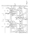
- the system shown in Figure 2 forms part of the workpiece processing device shown in Figure 3.
- the coating workpieces by an endless revolving shown only indicated here Link chain 12 transported.
- the transported through the link chain 12, on pivotally movable, in the transport direction deflectable transport tabs 13 held Workpieces are in a first coating station A with a first Application medium coated and then arrive after running one Drying oven (not shown) in a second coating station B, which in its Structure essentially that described above in connection with Fig.2 Device corresponds.
- the first coating station A and the second coating station B are each with a positioning device for setting a basic position of the respective Coater.
- the positioning device assigned to the first coating station here comprises two operable by hand crank devices 15 and 16 Spindle elements.
- the first coating station A is therefore both horizontal Direction as well as in the vertical direction of the respective workpiece dimensions can be positioned accordingly.
- the second coating station is also manual actuable hand crank devices 17 and 18 can be pre-positioned.
- the so prepositioned coating stations A and B are by separate drive units 19, 20 can be brought into a processing position in cycles, in particular can be raised, in which an application medium on the correspondingly fed workpiece 3 can be applied and the workpiece is possibly lifted off the holding mandrel.
- the drive units are used for the further transport of the coated workpieces 3 controlled such that at least the coating rollers 1, 2 or the whole Coating unit including housing can be lowered briefly so that the coated workpiece is removed and a new workpiece is fed can, without this resulting in uncontrollable contact of the workpieces and the coating roller comes.
- the structure of the coating stations A and B corresponds to that in FIG Connection with Fig. 2 described coating device. If necessary, you can of course i. V. m. a coating station A or B also coating stations can be used with a different structure.
- one or more of the coating rollers 1,2 also a contoured peripheral surface (here with two coating sections 1 a, 1b) have, in the event that only a portion 3a, 3b of the workpiece 3 to be coated while the rest of the workpiece is being coated (also from subsequent treatment, e.g. on an adhesive coating) remains free.
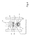
- FIG. 4 is one for carrying out a workpiece inner and / or outer coating provided embodiment of a device according to the invention shown.
- one is along its inner and / or outer peripheral surface rotationally symmetrical workpiece 3 to be coated onto a Bracket, e.g. a pair of support rollers 11 placed.
- This pair of support rollers 11 forms here the pair of support rollers supporting the workpiece at two support areas WP.
- the pair of support rollers at the same time form coating rollers for an outer coating of the workpiece 3 and can also be coupled to drive means for a rotary connection.
- the workpiece 3 to be coated can be rotated by the pair of support rollers 11 stored.
- a coating roller 1 provided with a coating medium into the workpiece 3 retracted.
- the coating roller 1 is connected to a rotary drive device.
- the workpiece 3 rests on the support rollers 11.
- the coating roller 1 and the workpiece supported on the support rollers 11 3 forms a uniform layer on the inner peripheral surface of the workpiece 3 from the application medium fed through the coating roller 1.
- a particularly uniform supply of the coating roller 1 with the coating medium can by means of feed channels formed in the coating roller 1 can be achieved.
- the pure rotary drive of the workpiece 3 can (Internal) coating roller 1 when the workpiece is rotatably supported by the support roller pair be enough.
- the coating roller 1 is preferably on a vertically movable here Carriage S mounted so that the workpiece 3 through the coating roller upwards moved to the frictional contact and rotary drive by the two drive rollers 28, 29 can be.
- the workpiece is driven in rotation via a workpiece drive motor 25, a here designed as an angular gear mechanism 26 and a coupled thereto Output gear 27.
- the output gear 27 is with the two drive rollers 28, 29th drive-connected.
- the workpiece 3 is lifted over the coating roller 1 and pressed against the drive rollers 12, 29. This becomes a forced drive of the workpiece 3 is reached and a uniform, high-quality coating is ensured.
- the lifting of the workpiece for the coating process has the Another advantage that the pair of support rollers 11 (without expensive ball bearings) can simply be carried out in the form of fixed support spikes. Besides, that will lower platen pair 11 then not in contact with coating material brought.
- the upper, raised drive rollers 28, 29 can also be used as Outside coating rollers can be formed.
- the coating roller 1 is, based on the workpiece 3, possibly in the radial direction movable.
- the coating roller 1 can as soon as the desired coating of the Inner surface of the workpiece 3 is reached, gradually from the inner peripheral surface of the Workpiece 3 are lifted off.
- the coating roller is preferred 1 continues to drive, causing the formation of any streaks on the inner peripheral surface of the workpiece 3 is avoided.
- the from the inner peripheral surface of the The workpiece 3 lifted coating roller 1 can now in the axial direction of the workpiece 3 are pulled out of the inner region of the workpiece 3.
- the workpiece can continue, in particular also inside a drying oven be rotated.
- Such an inner coating of the workpiece can be but also with the rotary table previously described in connection with Fig.1 carry out.
- the corresponding ones to be coated on the inside and / or outside Workpieces to those identified by the reference number 11 in FIG Support rollers (possibly also coating rollers) placed on and similar to the previous one described by means of a rotary drive inserted into the workpieces 3 Coating roller 1 coated.
- Drive rollers also force the respective workpiece to rotate movable.
- the workpiece also by lifting in drive connection with upper rotating drive rollers to be brought.
- the inner coating roller 1 by means of a vertically movable mandrel for guiding the workpiece into a drive and Coating layer replaceable (for external coating).
- Figure 5 shows a coating device again in a schematic representation a coating roller 1. If necessary, this can also be provided twice and the workpiece 3 through the coating rollers 1, 2 in a similar manner as in Fig. 1 be supported, the coating roller arrangement here being profiled Coating surface with coating sections 1a, 1b, in the event that only a cylinder section (two cylinder sections in the present example) of the workpiece 1 to be coated with edge scraper coating edge, while the other areas of the workpiece remain free of a coating.
- the device according to the invention is particularly suitable for coating ring or tubular components. With the device according to the invention also comparatively viscous fluids reliably on the corresponding Apply workpieces. This will result in a significantly reduced solvent consumption reached.
- the drying time of the coating medium is also determined by shortens the device according to the invention. Through reliable synchronization the rotational movement of the workpiece to be coated and the associated one Coating roller achieves a high surface quality. By the clock Moving or lowering or lifting the coating rollers is a collision-free Workpiece transport guaranteed.
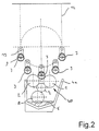
- Vibration damper sleeves are on radially from one Round table 10 projecting holding mandrels attached by means of a handling system.
- a correspondingly arranged on a holding mandrel 9 vibration damper sleeve 3 is lowered by rotating the rotary table 10 over an initially Coating device positioned.
- the coating device in the vertical direction raised until the vibration damper sleeve with its outer peripheral area sits on the first coating roller 1 and the second coating roller 2.
- the constantly rotating two application rollers 1 and 2 also displace them their own weight in the gap formed between the two application rollers 1 and 2 penetrating vibration damper sleeve in rotation and together support that Workpiece in the radial direction.
- the corrosion protection paint collecting in the bottom area of the tub 4 becomes continuous dispensed on the two coating rollers 1 and 2 and arrives thereby on the outer peripheral surface of the vibration damper sleeve.
- the Vibration damper sleeve 3 sufficiently in the area of its outer peripheral surface the corrosion protection paint is coated, the coating device is again lowered in the vertical direction and another, initially still uncoated Workpiece positioned over the coating device.
- Vibration damper sleeve is simultaneously moved further and gets into one Drip-off position into which, if necessary, drip-off corrosion protection paint into the tub 4 and thus can get back into the application medium sump 5.
- the coating device is raised again towards the workpiece 3.
- the invention is not restricted to the exemplary embodiment described above.
- the workpiece it is also possible to use the workpiece to be coated without the aid a rotary table or a transport chain, for example by means of a transfer device in the nip area formed between the two coating rollers 1 and 2 appeal.
- a transfer device in the nip area formed between the two coating rollers 1 and 2 appeal.
- Both when using the rotary table and when using the transport chain it is advantageously possible to use the coating device to move along a certain distance in the workpiece transport direction. This makes it possible to keep the rotary table or the transport chain constant To operate transport speed.
- these coating stations on different pitch circles preferably (seen in the radial direction) be arranged "on gap", so that the clock variability of the overall device (also in connection with a dryer and / or cycle-coordinated application of loading and unloading stations) and e.g. an odd number of Workpiece holding stations, arranged on a pitch circle, in connection with a even number of workpiece receiving stations, arranged on one further e.g. Pitch circle further outward can be provided.
- FIG. 6a Such a rotary table device is shown in FIG. 6a, in which a series of the first Workpiece receptacles 30 arranged on a radially outer first pitch circle 31 are. Within this first pitch circle there is a second pitch circle 32, on which a series of second workpiece holders 33 is arranged.
- the first are Workpiece receptacles 30, based on the second workpiece receptacles 33 for a gap arranged. Both the first workpiece fixtures and the second workpiece fixtures are provided in an odd number.
- the first and second workpiece holders 30, 33 are not about the axis of rotation Z of the rotary table device movable, but stationary with the rotary table device coupled. However, it is also possible to use the two pitch circle arrangements to be relatively movable to each other.
- the first and second workpiece holders 30, 33 formed such that the workpieces moved along the first pitch circle 31 towards the workpieces moving along the second pitch circle 32 are at a different axial height level.
- the radially inner second workpiece receptacles 33 Workpieces, seen in the vertical direction, higher than those lying further out first workpiece receptacles 30. This makes access to reached the workpieces held radially on the inside.
- Both the first workpiece holders 30 and the second workpiece holders 33 are provided with a drive device through which the in the workpiece holders each workpiece held rotatable about a vertical axis are.
- those in the first workpiece holders 30 held workpieces rotated at the same speed as that by the second workpiece holders 33 held workpieces.
- the workpiece turning organs of the first and second workpiece holders 30, 33 can, for example by means of a toothed belt.
- An external one is preferred first workpiece holder 30 with an adjacent inner second Workpiece holder 33 coupled.
- the rotary drive of the workpiece holding elements then takes place in the respective processing or treatment station by coupling a stationary drive device to the workpiece holders 30, 33.
- the switching of the rotary table device according to a predetermined Switching pattern is carried out by means of a rotary table drive device 34, which is in the present In the case of one controlled by a control device (not shown) Electric motor 35 which, via a gear 36 with a coaxial on the Rotary table transport device 10 attached drive gear 37 with the rotary table device 10 is coupled.
- the rotary table device 10 is rotatably supported in the exemplary embodiment shown through a roller bearing 38 that rotates a stationary base frame 39 couples with the rotary table device 10.
- a roller bearing 38 that rotates a stationary base frame 39 couples with the rotary table device 10.
- the height at which they are arranged along the inner second pitch circle 32 Workpieces held opposite the top of the rotary table device 10 are, preferably corresponds approximately to the radius of the inner, second partial circle 32.
- Workpieces held opposite the top of the rotary table device 10 are, preferably corresponds approximately to the radius of the inner, second partial circle 32.
- For coupling the workpieces to the workpiece holders 30, 33 can preferably rod-like, preferably arranged coaxially to the workpiece axis of rotation Holding members 42 are used. This advantageously makes it possible an undesirable precipitation of the application medium on the first and second To avoid workpiece holders 30, 33.
- the present invention enables a permissible number of workpiece pickups on a rotating transport device, preferably a rotary table, in Depends on the number of treatments required / possible per workpiece (Drying) and / or processing (coatings) determined by the permissible Number of workpiece holders from a common multiple of the number possible treatments and / or treatments determined and then provided is that from this and the number of planned / possible edits certain quotient is an integer.
Landscapes
- Coating Apparatus (AREA)
- Encapsulation Of And Coatings For Semiconductor Or Solid State Devices (AREA)
- Application Of Or Painting With Fluid Materials (AREA)
Applications Claiming Priority (3)
| Application Number | Priority Date | Filing Date | Title |
|---|---|---|---|
| DE29806593U | 1998-04-09 | ||
| DE29806593U DE29806593U1 (de) | 1998-04-09 | 1998-04-09 | Vorrichtung zum Beschichten eines Werkstücks |
| EP99107034A EP0949009A3 (fr) | 1998-04-09 | 1999-04-09 | Dispositif de revêtement de pièces |
Related Parent Applications (1)
| Application Number | Title | Priority Date | Filing Date |
|---|---|---|---|
| EP99107034A Division EP0949009A3 (fr) | 1998-04-09 | 1999-04-09 | Dispositif de revêtement de pièces |
Publications (2)
| Publication Number | Publication Date |
|---|---|
| EP1329264A2 true EP1329264A2 (fr) | 2003-07-23 |
| EP1329264A3 EP1329264A3 (fr) | 2004-03-10 |
Family
ID=8055615
Family Applications (2)
| Application Number | Title | Priority Date | Filing Date |
|---|---|---|---|
| EP99107034A Withdrawn EP0949009A3 (fr) | 1998-04-09 | 1999-04-09 | Dispositif de revêtement de pièces |
| EP03009433A Withdrawn EP1329264A3 (fr) | 1998-04-09 | 1999-04-09 | Méthode et appareil de traitement d'objets, en particulier pour le revêtement d'objets |
Family Applications Before (1)
| Application Number | Title | Priority Date | Filing Date |
|---|---|---|---|
| EP99107034A Withdrawn EP0949009A3 (fr) | 1998-04-09 | 1999-04-09 | Dispositif de revêtement de pièces |
Country Status (2)
| Country | Link |
|---|---|
| EP (2) | EP0949009A3 (fr) |
| DE (2) | DE29806593U1 (fr) |
Cited By (2)
| Publication number | Priority date | Publication date | Assignee | Title |
|---|---|---|---|---|
| CN106540846A (zh) * | 2017-01-10 | 2017-03-29 | 依合斯工程塑胶(上海)有限公司 | 一种轮毂刷胶装置 |
| TWI797607B (zh) * | 2021-05-04 | 2023-04-01 | 政鈺機械股份有限公司 | 應用於塗佈機的y型輸送裝置 |
Families Citing this family (11)
| Publication number | Priority date | Publication date | Assignee | Title |
|---|---|---|---|---|
| US6761931B1 (en) * | 2003-01-17 | 2004-07-13 | Delphi Technologies, Inc. | Method for piston coating |
| EP1712295A1 (fr) * | 2005-04-15 | 2006-10-18 | Josef van Baal GmbH | Appareil de revêtement de la surface extérieure de pièces en forme de manchon |
| CN109926263B (zh) * | 2019-02-25 | 2021-06-22 | 金光红 | 一种表面涂层涂抹装置 |
| CN110394252B (zh) * | 2019-07-03 | 2021-03-16 | 朱浩 | 一种pvc管自动喷漆设备 |
| CN110876998B (zh) * | 2019-12-12 | 2020-10-30 | 嘉兴福良纺织科技有限公司 | 一种用于圆边皮革的油边机 |
| CN112387512B (zh) * | 2020-10-15 | 2022-08-19 | 赵宇 | 一种旋转式木头蘸蜡装置 |
| CN112246553A (zh) * | 2020-10-28 | 2021-01-22 | 浙江骐盛电子有限公司 | 一种电阻加工设备 |
| CN112756183A (zh) * | 2020-12-16 | 2021-05-07 | 湖北永喆机械制造有限公司 | 一种用于重型越野特种车钣金涂装装置 |
| CN113042294B (zh) * | 2021-03-09 | 2023-01-24 | 深圳市宝科特精密科技有限公司 | 一种螺母加工用涂油装置 |
| CN114054278B (zh) * | 2021-12-09 | 2022-12-16 | 江苏鑫时创铝幕墙制造有限公司 | 一种隔热纳米自洁幕墙铝单板表面处理装置 |
| CN114950837B (zh) * | 2022-07-04 | 2023-04-28 | 盐城工业职业技术学院 | 一种瓷刻产品赋彩设备及其制备工艺 |
Family Cites Families (8)
| Publication number | Priority date | Publication date | Assignee | Title |
|---|---|---|---|---|
| US1931252A (en) * | 1930-10-24 | 1933-10-17 | Robert Becht Co | Can varnishing machine |
| US2206686A (en) * | 1937-08-04 | 1940-07-02 | Classic Glass Inc | Apparatus for applying decorative color effects to glass and ceramic ware |
| FR2504032B1 (fr) * | 1981-04-15 | 1985-11-29 | Haut Rhin Manufacture Machines | Machine de traitement en continu, notamment de vernissage en continu de corps de revolution |
| HU184030B (en) * | 1982-09-22 | 1984-06-28 | Egyesuelt Izzolampa | Apparatus for electrostatic coating bulb of light sources |
| JPS61111444A (ja) * | 1984-11-06 | 1986-05-29 | Olympus Optical Co Ltd | 化学分析装置 |
| US5275664A (en) * | 1991-04-26 | 1994-01-04 | Gencorp Inc. | Apparatus for application of a material to an external surface of items of manufacture |
| US5183509A (en) * | 1991-04-26 | 1993-02-02 | Gencorp Inc. | Apparatus for application of a material to an internal surface of items of manufacture |
| JP2908923B2 (ja) * | 1991-12-18 | 1999-06-23 | 日本電子株式会社 | 生化学自動分析装置 |
-
1998
- 1998-04-09 DE DE29806593U patent/DE29806593U1/de not_active Expired - Lifetime
-
1999
- 1999-04-09 DE DE29924534U patent/DE29924534U1/de not_active Expired - Lifetime
- 1999-04-09 EP EP99107034A patent/EP0949009A3/fr not_active Withdrawn
- 1999-04-09 EP EP03009433A patent/EP1329264A3/fr not_active Withdrawn
Cited By (2)
| Publication number | Priority date | Publication date | Assignee | Title |
|---|---|---|---|---|
| CN106540846A (zh) * | 2017-01-10 | 2017-03-29 | 依合斯工程塑胶(上海)有限公司 | 一种轮毂刷胶装置 |
| TWI797607B (zh) * | 2021-05-04 | 2023-04-01 | 政鈺機械股份有限公司 | 應用於塗佈機的y型輸送裝置 |
Also Published As
| Publication number | Publication date |
|---|---|
| EP0949009A3 (fr) | 2002-08-07 |
| DE29924534U1 (de) | 2003-12-11 |
| EP0949009A2 (fr) | 1999-10-13 |
| DE29806593U1 (de) | 1999-08-12 |
| EP1329264A3 (fr) | 2004-03-10 |
Similar Documents
| Publication | Publication Date | Title |
|---|---|---|
| DE3715969C2 (fr) | ||
| EP1329264A2 (fr) | Méthode et appareil de traitement d'objets, en particulier pour le revêtement d'objets | |
| DE2255582A1 (de) | Vorrichtung zum bedrucken rohrfoermiger gegenstaende | |
| DE2743378C2 (de) | Vorrichtung zur Handhabung von im wesentlichen zylindrischen Behältern | |
| DE19612749C2 (de) | Vorrichtung zum Streichen der Außenumfangsoberfläche eines säulenartigen Körpers mit einem Streichmittel | |
| DE2728741C2 (fr) | ||
| DE4436275C2 (de) | Verfahren und Vorrichtung zum Bedrucken von Einzelobjekten | |
| DE2902352C3 (de) | Verfahren und Vorrichtung zum Tauchbeschichten von Werkstücken, insbesondere von Containern | |
| DE20217416U1 (de) | Vorrichtung zum Beschichten eines Werkstücks mit Pulver | |
| DE3219556C2 (fr) | ||
| DE3800129C2 (de) | Verfahren zum Auftragen von Fett und dafür geignete Vorrichtung | |
| DE2618767C3 (de) | Werkstück-Fördervorrichtung zum Beschicken bzw. Entleeren von Bearbeitungsstationen | |
| EP0024029A1 (fr) | Dispositif pour l'application de revêtements à une matière en bande, en particulier à des bandes métalliques | |
| DE29920707U1 (de) | Vorrichtung zum Beschichten eines Werkstücks | |
| DE709523C (de) | Vorrichtung zum Aufbringen von Schutzueberzuegen aus Lack o. dgl. auf die Laengsnaehte im Innern von Konservendosenruempfen | |
| DE69010056T2 (de) | Vorrichtung zum Besäumen von Dosenenden. | |
| DE2821192C3 (de) | Verfahren und Anlage zum Tauchbeschichten von Teilen | |
| EP0929379B1 (fr) | Procede et dispositif pour le traitement de pieces, et poste de reception de pieces pour un tel dispositif | |
| DE2803352C2 (de) | Vorrichtung zum gleichzeitigen Beschichten und Bedrucken von zylindrischen Gegenständen | |
| DE19527733C1 (de) | Verfahren und Vorrichtung zum Innenbeschichten von Rohrstücken | |
| DE2540487C3 (de) | Vorrichtung zum gleichzeitigen Beschichten und Bedrucken von zylindrischen Gegenständen | |
| DE4015146A1 (de) | Verfahren und anlage zum entfernen anhaftenden schmiermittels von werkstuecken, wie schrauben, bolzen, muttern oder nieten | |
| DE3917889C2 (fr) | ||
| DE1811356A1 (de) | Maschine zum Bedrucken,Lackieren,Ausruesten,Etikettieren usw.von Tuben,Huelsen oder rohrfoermigen Werkstuecken in kontinuierlichem Fluss | |
| DE29622862U1 (de) | System und Einrichtung zur Bearbeitung von Werkstücken sowie Werkstückaufnahmestation für eine derartige Einrichtung |
Legal Events
| Date | Code | Title | Description |
|---|---|---|---|
| PUAI | Public reference made under article 153(3) epc to a published international application that has entered the european phase |
Free format text: ORIGINAL CODE: 0009012 |
|
| AC | Divisional application: reference to earlier application |
Ref document number: 0949009 Country of ref document: EP Kind code of ref document: P |
|
| AK | Designated contracting states |
Designated state(s): AT BE CH CY DE DK ES FI FR GB GR IE IT LI LU MC NL PT SE |
|
| PUAL | Search report despatched |
Free format text: ORIGINAL CODE: 0009013 |
|
| AK | Designated contracting states |
Kind code of ref document: A3 Designated state(s): AT BE CH CY DE DK ES FI FR GB GR IE IT LI LU MC NL PT SE |
|
| AKX | Designation fees paid | ||
| REG | Reference to a national code |
Ref country code: DE Ref legal event code: 8566 |
|
| STAA | Information on the status of an ep patent application or granted ep patent |
Free format text: STATUS: THE APPLICATION IS DEEMED TO BE WITHDRAWN |
|
| 18D | Application deemed to be withdrawn |
Effective date: 20040911 |