EP0013772A1 - Appareil pour démonter une pale du dernier disque d'un rotor - Google Patents
Appareil pour démonter une pale du dernier disque d'un rotor Download PDFInfo
- Publication number
- EP0013772A1 EP0013772A1 EP19790200043 EP79200043A EP0013772A1 EP 0013772 A1 EP0013772 A1 EP 0013772A1 EP 19790200043 EP19790200043 EP 19790200043 EP 79200043 A EP79200043 A EP 79200043A EP 0013772 A1 EP0013772 A1 EP 0013772A1
- Authority
- EP
- European Patent Office
- Prior art keywords
- blades
- holding
- rotor
- brackets
- clamping
- Prior art date
- Legal status (The legal status is an assumption and is not a legal conclusion. Google has not performed a legal analysis and makes no representation as to the accuracy of the status listed.)
- Granted
Links
Images



Classifications
-
- F—MECHANICAL ENGINEERING; LIGHTING; HEATING; WEAPONS; BLASTING
- F01—MACHINES OR ENGINES IN GENERAL; ENGINE PLANTS IN GENERAL; STEAM ENGINES
- F01D—NON-POSITIVE DISPLACEMENT MACHINES OR ENGINES, e.g. STEAM TURBINES
- F01D25/00—Component parts, details, or accessories, not provided for in, or of interest apart from, other groups
- F01D25/28—Supporting or mounting arrangements, e.g. for turbine casing
- F01D25/285—Temporary support structures, e.g. for testing, assembling, installing, repairing; Assembly methods using such structures
-
- B—PERFORMING OPERATIONS; TRANSPORTING
- B23—MACHINE TOOLS; METAL-WORKING NOT OTHERWISE PROVIDED FOR
- B23P—METAL-WORKING NOT OTHERWISE PROVIDED FOR; COMBINED OPERATIONS; UNIVERSAL MACHINE TOOLS
- B23P19/00—Machines for simply fitting together or separating metal parts or objects, or metal and non-metal parts, whether or not involving some deformation; Tools or devices therefor so far as not provided for in other classes
- B23P19/02—Machines for simply fitting together or separating metal parts or objects, or metal and non-metal parts, whether or not involving some deformation; Tools or devices therefor so far as not provided for in other classes for connecting objects by press fit or for detaching same
- B23P19/025—For detaching only
-
- B—PERFORMING OPERATIONS; TRANSPORTING
- B25—HAND TOOLS; PORTABLE POWER-DRIVEN TOOLS; MANIPULATORS
- B25B—TOOLS OR BENCH DEVICES NOT OTHERWISE PROVIDED FOR, FOR FASTENING, CONNECTING, DISENGAGING, OR HOLDING
- B25B27/00—Hand tools, specially adapted for fitting together or separating parts or objects whether or not involving some deformation, not otherwise provided for
- B25B27/02—Hand tools, specially adapted for fitting together or separating parts or objects whether or not involving some deformation, not otherwise provided for for connecting objects by press fit or detaching same
Definitions
- the present invention relates to a device for dismantling rotor blades from steam turbines, in particular for blades from output stages.
- a clamping device with holding jaws for holding the blades is arranged on a swivel-shaped swivel device.
- the arrangement of a clamping device with holding jaws on a swivel device has the advantage that the swivel device designed in the form of a bracket can be hung on a lifting device, for example on a crane, and can be swiveled out of the turbine in a simple manner after the relevant blade has been removed.
- the bow-like design of the swivel device is further advantageous in that no disability occurs during dismantling, since the vertical arm of the swivel device is arranged to the side of the clamping device and at a distance from it.
- two receptacles with fuses for the tensioning device are provided on the swivel device.
- the dismantling device can be used for both floods of a low-pressure stage without the tensioning device having to be replaced.
- a further embodiment of the subject matter of the invention is characterized in that the pivoting device is formed in two parts and part of the same is rotatably arranged on a joint with the tensioning device and the holding jaws, and in that the holding jaws have brackets which are designed analogously to the blade profile.
- the two-part design of the swivel device enables the clamping device to be easily rotated through 180 ° in order to use it to remove turbine blades in both directions of rotation. Damage to the blade surface is avoided by the design of the brackets analogous to the blade profile.
- a retaining spring for fixing the airfoils and a relief screw for loosening the airfoil are arranged between the brackets, or a clamping screw is provided between the brackets for holding the airfoil.
- the arrangement of holding elements with holders between the holding jaws allows simple fixing of the blades and prevents them from slipping out of the holders. At the same time, the holders can be released in a simple manner.
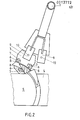
- a bracket-like swivel device 1 which has a ring 2 at its upper end which is arranged so that the suspension point can be set exactly above the center of gravity of the dismantling device when a turbine blade 4 is attached to it.
- a tensioning device 3 is provided, which acts on the base of a turbine blade 4 of a rotor 5.
- the clamping device 3 (Fig..2) three holding jaws 6 are fastened with screws 7.
- the holding jaws 6 on the support side of the turbine blade 4 have wedges 8 which are made of a soft material in order to avoid damage to the turbine blade 4.
- the clamping device 3 is fastened to the swivel device 1 by means of receptacles 9 and fuses 10.
- the receptacles 9 are preferably provided in pairs at an angle to one another, as a result of which the device can be used for both floods of a turbine low-pressure stage.
- a joint 11 is arranged at the lower end of the pivoting device 1, with which the clamping device 3 can be rotated so that the holding jaws 6 each correspond to the position of the turbine blades 4 and can encompass them.
- FIG. 4 consists, analogously to FIG. 1, of the bracket-like swivel device 1, at the lower end of which the holding jaws 6 are arranged, which are designed similar to the profile of the turbine blades 4 and comprise the blade blades.
- the holding jaws 6 provided with a swivel joint 13 have holders 17 which are pressed together by means of springs 12 or a clamping screw 14.
- the holding jaws 6 are inserted in the swivel device 1 and by means of a securing bolt 15 secured.
- the design of the brackets 17 with the spring 12 also has a relief screw 16 for loosening the two brackets 17.
Landscapes
- Engineering & Computer Science (AREA)
- Mechanical Engineering (AREA)
- General Engineering & Computer Science (AREA)
- Turbine Rotor Nozzle Sealing (AREA)
- Working Measures On Existing Buildindgs (AREA)
Priority Applications (5)
| Application Number | Priority Date | Filing Date | Title |
|---|---|---|---|
| EP19790200043 EP0013772B1 (fr) | 1979-01-24 | 1979-01-24 | Appareil pour démonter une pale du dernier disque d'un rotor |
| DE7979200043T DE2965482D1 (en) | 1979-01-24 | 1979-01-24 | Apparatus for removing an end blade from a rotor |
| DE19797906540 DE7906540U1 (de) | 1979-01-24 | 1979-03-09 | Vorrichtung zur demontage von rotorschaufeln |
| DK24580A DK24580A (da) | 1979-01-24 | 1980-01-21 | Anordning til demontering af rotorskovle |
| CA000344319A CA1150938A (fr) | 1979-01-24 | 1980-01-24 | Methode et dispositif pour separer des aubes de leur rotor |
Applications Claiming Priority (1)
| Application Number | Priority Date | Filing Date | Title |
|---|---|---|---|
| EP19790200043 EP0013772B1 (fr) | 1979-01-24 | 1979-01-24 | Appareil pour démonter une pale du dernier disque d'un rotor |
Publications (2)
| Publication Number | Publication Date |
|---|---|
| EP0013772A1 true EP0013772A1 (fr) | 1980-08-06 |
| EP0013772B1 EP0013772B1 (fr) | 1983-05-25 |
Family
ID=8186268
Family Applications (1)
| Application Number | Title | Priority Date | Filing Date |
|---|---|---|---|
| EP19790200043 Expired EP0013772B1 (fr) | 1979-01-24 | 1979-01-24 | Appareil pour démonter une pale du dernier disque d'un rotor |
Country Status (4)
| Country | Link |
|---|---|
| EP (1) | EP0013772B1 (fr) |
| CA (1) | CA1150938A (fr) |
| DE (2) | DE2965482D1 (fr) |
| DK (1) | DK24580A (fr) |
Cited By (14)
| Publication number | Priority date | Publication date | Assignee | Title |
|---|---|---|---|---|
| US5152058A (en) * | 1990-06-21 | 1992-10-06 | Turbine Blading Limited | Repair of turbine blades |
| US5511308A (en) * | 1994-05-06 | 1996-04-30 | Ontario Hydro | Method and apparatus for turbine blade rehabilitation |
| EP1149662A1 (fr) * | 2000-04-25 | 2001-10-31 | ALSTOM Power N.V. | Procédé et dispositif de démontage d'une aube de turbine |
| EP1614856A1 (fr) * | 2004-07-09 | 2006-01-11 | Siemens Aktiengesellschaft | Dispositif pour démonter une aube de turbine ou compresseur |
| EP1541804A3 (fr) * | 2003-09-24 | 2011-01-12 | Alstom Technology Ltd | Pale de rotor pour une turbomachine et outil d'extraction associé |
| EP2495404A1 (fr) * | 2011-03-01 | 2012-09-05 | Rolls-Royce plc | Support de pièce de travail d'un moteur à turbine à gaz |
| GB2516676A (en) * | 2013-07-30 | 2015-02-04 | Rolls Royce Plc | Aerofoil component handling tool |
| CN105834990A (zh) * | 2016-05-19 | 2016-08-10 | 国家电网公司 | 一种分块式水导瓦拆卸方法及拆卸工具 |
| EP3381612A1 (fr) * | 2017-03-31 | 2018-10-03 | General Electric Company | Appareils de montage fixés à des aubes de turbine de systèmes de turbine |
| CN109333412A (zh) * | 2018-12-07 | 2019-02-15 | 中国航发南方工业有限公司 | 涡轮转子组件的锁片分解工装 |
| CN112518307A (zh) * | 2020-12-14 | 2021-03-19 | 湖州广源机电安装有限公司 | 一种机电设备中电器元件的快速安装装置 |
| CN114378555A (zh) * | 2022-01-27 | 2022-04-22 | 苏州立德麦自动化有限公司 | 一种重型卡车自锁螺母母头压卡圈装置 |
| CN114762926A (zh) * | 2021-01-13 | 2022-07-19 | 中国航发商用航空发动机有限责任公司 | 涡轮叶片拆卸工具及方法 |
| US12104361B2 (en) | 2018-12-10 | 2024-10-01 | Esco Group Llc | System and process for conducting in-field operations |
Families Citing this family (4)
| Publication number | Priority date | Publication date | Assignee | Title |
|---|---|---|---|---|
| CN102794725B (zh) * | 2011-05-25 | 2016-06-15 | 迪皮埃复材构件(太仓)有限公司 | 一种后梁定位工装装置 |
| GB201804798D0 (en) * | 2018-03-26 | 2018-05-09 | Rolls Royce Plc | Blade removal method and apparatus |
| IT202100032111A1 (it) | 2021-12-22 | 2023-06-22 | Fidia Farm Spa | Nuovi sostituti biocompatibili dell’umor vitreo |
| IT202300023433A1 (it) | 2023-11-07 | 2025-05-07 | Univ Degli Studi Di Catania | Derivati di acido ialuronico fotogeneratori di ossido nitrico |
Citations (3)
| Publication number | Priority date | Publication date | Assignee | Title |
|---|---|---|---|---|
| US2128268A (en) * | 1931-05-14 | 1938-08-30 | Lisle F Small | Means for securing turbine blades |
| US3857158A (en) * | 1972-12-19 | 1974-12-31 | D Costello | Method and apparatus for removing condenser tubes from surface condensers |
| US3908258A (en) * | 1974-12-06 | 1975-09-30 | Thomas Barty | Hydraulic puller |
-
1979
- 1979-01-24 DE DE7979200043T patent/DE2965482D1/de not_active Expired
- 1979-01-24 EP EP19790200043 patent/EP0013772B1/fr not_active Expired
- 1979-03-09 DE DE19797906540 patent/DE7906540U1/de not_active Expired
-
1980
- 1980-01-21 DK DK24580A patent/DK24580A/da not_active Application Discontinuation
- 1980-01-24 CA CA000344319A patent/CA1150938A/fr not_active Expired
Patent Citations (3)
| Publication number | Priority date | Publication date | Assignee | Title |
|---|---|---|---|---|
| US2128268A (en) * | 1931-05-14 | 1938-08-30 | Lisle F Small | Means for securing turbine blades |
| US3857158A (en) * | 1972-12-19 | 1974-12-31 | D Costello | Method and apparatus for removing condenser tubes from surface condensers |
| US3908258A (en) * | 1974-12-06 | 1975-09-30 | Thomas Barty | Hydraulic puller |
Cited By (26)
| Publication number | Priority date | Publication date | Assignee | Title |
|---|---|---|---|---|
| US5152058A (en) * | 1990-06-21 | 1992-10-06 | Turbine Blading Limited | Repair of turbine blades |
| US5511308A (en) * | 1994-05-06 | 1996-04-30 | Ontario Hydro | Method and apparatus for turbine blade rehabilitation |
| EP1149662A1 (fr) * | 2000-04-25 | 2001-10-31 | ALSTOM Power N.V. | Procédé et dispositif de démontage d'une aube de turbine |
| US6571471B2 (en) | 2000-04-25 | 2003-06-03 | Alstom (Switzerland) Ltd | Method and device for demounting a turbine blade |
| EP1541804A3 (fr) * | 2003-09-24 | 2011-01-12 | Alstom Technology Ltd | Pale de rotor pour une turbomachine et outil d'extraction associé |
| US7455505B2 (en) | 2004-07-09 | 2008-11-25 | Siemens Aktiengesellschaft | Device for the demounting of blades of a turbine or of a compressor |
| EP1614856A1 (fr) * | 2004-07-09 | 2006-01-11 | Siemens Aktiengesellschaft | Dispositif pour démonter une aube de turbine ou compresseur |
| EP2495404A1 (fr) * | 2011-03-01 | 2012-09-05 | Rolls-Royce plc | Support de pièce de travail d'un moteur à turbine à gaz |
| US9022370B2 (en) | 2011-03-01 | 2015-05-05 | Rolls-Royce Plc | Workpiece support |
| US9512722B2 (en) | 2013-07-30 | 2016-12-06 | Rolls-Royce Plc | Aerofoil component handling tool |
| GB2516676A (en) * | 2013-07-30 | 2015-02-04 | Rolls Royce Plc | Aerofoil component handling tool |
| EP2832501A3 (fr) * | 2013-07-30 | 2015-07-29 | Rolls-Royce plc | Outil de manipulation de composant de surface portante |
| GB2516676B (en) * | 2013-07-30 | 2016-02-24 | Rolls Royce Plc | Aerofoil component handling tool |
| CN105834990A (zh) * | 2016-05-19 | 2016-08-10 | 国家电网公司 | 一种分块式水导瓦拆卸方法及拆卸工具 |
| EP3381612A1 (fr) * | 2017-03-31 | 2018-10-03 | General Electric Company | Appareils de montage fixés à des aubes de turbine de systèmes de turbine |
| CN108691574A (zh) * | 2017-03-31 | 2018-10-23 | 通用电气公司 | 装固到涡轮系统的涡轮翼型件的安装设备 |
| US10408091B2 (en) | 2017-03-31 | 2019-09-10 | General Electric Company | Mounting apparatuses secured to turbine airfoils of turbine systems |
| US10920620B2 (en) | 2017-03-31 | 2021-02-16 | General Electric Company | Mounting apparatuses secured to turbine airfoils of turbine systems |
| CN108691574B (zh) * | 2017-03-31 | 2021-11-26 | 通用电气公司 | 装固到涡轮系统的涡轮翼型件的安装设备 |
| CN109333412A (zh) * | 2018-12-07 | 2019-02-15 | 中国航发南方工业有限公司 | 涡轮转子组件的锁片分解工装 |
| US12104361B2 (en) | 2018-12-10 | 2024-10-01 | Esco Group Llc | System and process for conducting in-field operations |
| CN112518307A (zh) * | 2020-12-14 | 2021-03-19 | 湖州广源机电安装有限公司 | 一种机电设备中电器元件的快速安装装置 |
| CN114762926A (zh) * | 2021-01-13 | 2022-07-19 | 中国航发商用航空发动机有限责任公司 | 涡轮叶片拆卸工具及方法 |
| CN114762926B (zh) * | 2021-01-13 | 2023-08-04 | 中国航发商用航空发动机有限责任公司 | 涡轮叶片拆卸工具及方法 |
| CN114378555A (zh) * | 2022-01-27 | 2022-04-22 | 苏州立德麦自动化有限公司 | 一种重型卡车自锁螺母母头压卡圈装置 |
| CN114378555B (zh) * | 2022-01-27 | 2023-09-01 | 苏州立德麦自动化有限公司 | 一种重型卡车自锁螺母母头压卡圈装置 |
Also Published As
| Publication number | Publication date |
|---|---|
| DE2965482D1 (en) | 1983-07-07 |
| CA1150938A (fr) | 1983-08-02 |
| EP0013772B1 (fr) | 1983-05-25 |
| DK24580A (da) | 1980-07-25 |
| DE7906540U1 (de) | 1980-07-03 |
Similar Documents
| Publication | Publication Date | Title |
|---|---|---|
| EP0013772A1 (fr) | Appareil pour démonter une pale du dernier disque d'un rotor | |
| DE2529238C2 (de) | Ellenbogengelenk-Endoprothese | |
| DE2512705A1 (de) | Verbesserungen an schienenschneidemaschinen | |
| EP0344671A2 (fr) | Dispositif de fixation d'une pale de propfan à pas variable | |
| DE2201005C3 (de) | Greifklemme zum Heben eines mit Rändern versehenen Fasses in aufrechter Lage | |
| DE3142572C2 (de) | Vorrichtung zum lösbaren Verbinden von Seilenden, insbesondere von Seilen bei umlaufenden Seiltrieben, Seilförderern oder Aufhängungen | |
| DE1804097A1 (de) | Transportvorrichtung | |
| DE2311199C2 (de) | Vorrichtung zum Verriegeln von Plattformen an Gerüstteilen | |
| AT137700B (de) | Abnehmbare Steigvorrichtung für Schneeschuhe. | |
| DE761450C (de) | Sicherheitsrasierapparat mit einem aus zwei Teilen bestehenden Kamm, wobei die Teile mit zwei biegsamen oder starren Flanschen eines hierzu angepassten Griffes verbundensind | |
| DE335435C (de) | Buerstenhalter fuer elektrische Maschinen mit zwei ver- und feststellbaren Gelenken | |
| DE2722522C2 (de) | Messerhalterung an Zerspanern | |
| EP0806645A2 (fr) | Dispositif de fixation pour retenir les roues de motocyclettes sur l'axe d'une machine d'équilibrage | |
| DD212678B1 (de) | Vorrichtung zum anpassen einer laufradschaufel fuer das anschweissen an die kalotte eines saugzug-laufrades | |
| DE371714C (de) | Klemmbefestigung fuer Greifer oder Hilfsfelgen an Triebraedern fuer Zugmaschinen | |
| DE1053426B (de) | Lagerung eines mit einer Bremse versehenen Kettenbaumes bei Webstuehlen | |
| DE7720352U1 (de) | Vorrichtung zum heben, senken und/oder abstuetzen von kabinen o.dgl., vorzugsweise rettungskabinen | |
| DE453402C (de) | Garnreinigungsvorrichtung | |
| DE340293C (de) | Vorrichtung zum Aufhaengen transportabler Werkzeugmaschinen mittels Kette | |
| DE619215C (de) | Kurbelwelle fuer Gabelheuwender | |
| DE683511C (de) | Fahrzeugraeder mit einem Kranz, in welchem Hohlkehlen zur Aufnahme von Greifern vorgesehen sind | |
| DE69721515T2 (de) | Ein Rohling und eine Vorrichtung zum Herstellen von präzisen Formteilen | |
| DE512593C (de) | Vorrichtung zum Entfernen von Huehneraugen o. dgl. | |
| DE914202C (de) | Anordnung und Verfahren zum Roden von Stubben | |
| DE2426231C3 (de) | Vorrichtung zum Wenden und Aufrichten von Turbinenläufern |
Legal Events
| Date | Code | Title | Description |
|---|---|---|---|
| AK | Designated contracting states |
Designated state(s): BE CH DE FR GB IT LU NL SE |
|
| PUAI | Public reference made under article 153(3) epc to a published international application that has entered the european phase |
Free format text: ORIGINAL CODE: 0009012 |
|
| AK | Designated contracting states |
Designated state(s): CH DE FR NL SE |
|
| 17P | Request for examination filed |
Effective date: 19801127 |
|
| RAP1 | Party data changed (applicant data changed or rights of an application transferred) |
Owner name: BBC AKTIENGESELLSCHAFT BROWN, BOVERI & CIE. |
|
| GRAA | (expected) grant |
Free format text: ORIGINAL CODE: 0009210 |
|
| AK | Designated contracting states |
Designated state(s): CH DE FR NL SE |
|
| REF | Corresponds to: |
Ref document number: 2965482 Country of ref document: DE Date of ref document: 19830707 |
|
| ET | Fr: translation filed | ||
| PLBI | Opposition filed |
Free format text: ORIGINAL CODE: 0009260 |
|
| 26 | Opposition filed |
Opponent name: KRAFTWERK UNION AKTIENGESELLSCHAFT Effective date: 19840224 |
|
| PLBN | Opposition rejected |
Free format text: ORIGINAL CODE: 0009273 |
|
| STAA | Information on the status of an ep patent application or granted ep patent |
Free format text: STATUS: OPPOSITION REJECTED |
|
| 27O | Opposition rejected |
Effective date: 19841124 |
|
| NLR2 | Nl: decision of opposition | ||
| PGFP | Annual fee paid to national office [announced via postgrant information from national office to epo] |
Ref country code: NL Payment date: 19890131 Year of fee payment: 14 |
|
| PGFP | Annual fee paid to national office [announced via postgrant information from national office to epo] |
Ref country code: FR Payment date: 19901217 Year of fee payment: 13 |
|
| PGFP | Annual fee paid to national office [announced via postgrant information from national office to epo] |
Ref country code: SE Payment date: 19901227 Year of fee payment: 13 |
|
| PGFP | Annual fee paid to national office [announced via postgrant information from national office to epo] |
Ref country code: DE Payment date: 19910321 Year of fee payment: 13 |
|
| PGFP | Annual fee paid to national office [announced via postgrant information from national office to epo] |
Ref country code: CH Payment date: 19910422 Year of fee payment: 13 |
|
| PG25 | Lapsed in a contracting state [announced via postgrant information from national office to epo] |
Ref country code: SE Effective date: 19920125 |
|
| PG25 | Lapsed in a contracting state [announced via postgrant information from national office to epo] |
Ref country code: CH Effective date: 19920131 |
|
| PG25 | Lapsed in a contracting state [announced via postgrant information from national office to epo] |
Ref country code: NL Effective date: 19920801 |
|
| NLV4 | Nl: lapsed or anulled due to non-payment of the annual fee | ||
| PG25 | Lapsed in a contracting state [announced via postgrant information from national office to epo] |
Ref country code: FR Effective date: 19920930 |
|
| REG | Reference to a national code |
Ref country code: CH Ref legal event code: PL |
|
| PG25 | Lapsed in a contracting state [announced via postgrant information from national office to epo] |
Ref country code: DE Effective date: 19921001 |
|
| REG | Reference to a national code |
Ref country code: FR Ref legal event code: ST |
|
| EUG | Se: european patent has lapsed |
Ref document number: 79200043.2 Effective date: 19920806 |
|
| PLAB | Opposition data, opponent's data or that of the opponent's representative modified |
Free format text: ORIGINAL CODE: 0009299OPPO |