EP1149662A1 - Procédé et dispositif de démontage d'une aube de turbine - Google Patents
Procédé et dispositif de démontage d'une aube de turbine Download PDFInfo
- Publication number
- EP1149662A1 EP1149662A1 EP01108282A EP01108282A EP1149662A1 EP 1149662 A1 EP1149662 A1 EP 1149662A1 EP 01108282 A EP01108282 A EP 01108282A EP 01108282 A EP01108282 A EP 01108282A EP 1149662 A1 EP1149662 A1 EP 1149662A1
- Authority
- EP
- European Patent Office
- Prior art keywords
- blade
- turbine blade
- disassembly
- hook
- turbine
- Prior art date
- Legal status (The legal status is an assumption and is not a legal conclusion. Google has not performed a legal analysis and makes no representation as to the accuracy of the status listed.)
- Granted
Links
Images

Classifications
-
- B—PERFORMING OPERATIONS; TRANSPORTING
- B23—MACHINE TOOLS; METAL-WORKING NOT OTHERWISE PROVIDED FOR
- B23P—METAL-WORKING NOT OTHERWISE PROVIDED FOR; COMBINED OPERATIONS; UNIVERSAL MACHINE TOOLS
- B23P6/00—Restoring or reconditioning objects
- B23P6/002—Repairing turbine components, e.g. moving or stationary blades, rotors
-
- B—PERFORMING OPERATIONS; TRANSPORTING
- B23—MACHINE TOOLS; METAL-WORKING NOT OTHERWISE PROVIDED FOR
- B23P—METAL-WORKING NOT OTHERWISE PROVIDED FOR; COMBINED OPERATIONS; UNIVERSAL MACHINE TOOLS
- B23P19/00—Machines for simply fitting together or separating metal parts or objects, or metal and non-metal parts, whether or not involving some deformation; Tools or devices therefor so far as not provided for in other classes
- B23P19/02—Machines for simply fitting together or separating metal parts or objects, or metal and non-metal parts, whether or not involving some deformation; Tools or devices therefor so far as not provided for in other classes for connecting objects by press fit or for detaching same
- B23P19/025—For detaching only
-
- B—PERFORMING OPERATIONS; TRANSPORTING
- B25—HAND TOOLS; PORTABLE POWER-DRIVEN TOOLS; MANIPULATORS
- B25B—TOOLS OR BENCH DEVICES NOT OTHERWISE PROVIDED FOR, FOR FASTENING, CONNECTING, DISENGAGING, OR HOLDING
- B25B27/00—Hand tools, specially adapted for fitting together or separating parts or objects whether or not involving some deformation, not otherwise provided for
- B25B27/02—Hand tools, specially adapted for fitting together or separating parts or objects whether or not involving some deformation, not otherwise provided for for connecting objects by press fit or detaching same
- B25B27/026—Hand tools, specially adapted for fitting together or separating parts or objects whether or not involving some deformation, not otherwise provided for for connecting objects by press fit or detaching same fluid driven
-
- F—MECHANICAL ENGINEERING; LIGHTING; HEATING; WEAPONS; BLASTING
- F01—MACHINES OR ENGINES IN GENERAL; ENGINE PLANTS IN GENERAL; STEAM ENGINES
- F01D—NON-POSITIVE DISPLACEMENT MACHINES OR ENGINES, e.g. STEAM TURBINES
- F01D25/00—Component parts, details, or accessories, not provided for in, or of interest apart from, other groups
- F01D25/28—Supporting or mounting arrangements, e.g. for turbine casing
- F01D25/285—Temporary support structures, e.g. for testing, assembling, installing, repairing; Assembly methods using such structures
-
- F—MECHANICAL ENGINEERING; LIGHTING; HEATING; WEAPONS; BLASTING
- F01—MACHINES OR ENGINES IN GENERAL; ENGINE PLANTS IN GENERAL; STEAM ENGINES
- F01D—NON-POSITIVE DISPLACEMENT MACHINES OR ENGINES, e.g. STEAM TURBINES
- F01D5/00—Blades; Blade-carrying members; Heating, heat-insulating, cooling or antivibration means on the blades or the members
- F01D5/005—Repairing methods or devices
-
- F—MECHANICAL ENGINEERING; LIGHTING; HEATING; WEAPONS; BLASTING
- F05—INDEXING SCHEMES RELATING TO ENGINES OR PUMPS IN VARIOUS SUBCLASSES OF CLASSES F01-F04
- F05D—INDEXING SCHEME FOR ASPECTS RELATING TO NON-POSITIVE-DISPLACEMENT MACHINES OR ENGINES, GAS-TURBINES OR JET-PROPULSION PLANTS
- F05D2230/00—Manufacture
- F05D2230/70—Disassembly methods
-
- Y—GENERAL TAGGING OF NEW TECHNOLOGICAL DEVELOPMENTS; GENERAL TAGGING OF CROSS-SECTIONAL TECHNOLOGIES SPANNING OVER SEVERAL SECTIONS OF THE IPC; TECHNICAL SUBJECTS COVERED BY FORMER USPC CROSS-REFERENCE ART COLLECTIONS [XRACs] AND DIGESTS
- Y10—TECHNICAL SUBJECTS COVERED BY FORMER USPC
- Y10T—TECHNICAL SUBJECTS COVERED BY FORMER US CLASSIFICATION
- Y10T29/00—Metal working
- Y10T29/49—Method of mechanical manufacture
- Y10T29/49316—Impeller making
- Y10T29/49318—Repairing or disassembling
-
- Y—GENERAL TAGGING OF NEW TECHNOLOGICAL DEVELOPMENTS; GENERAL TAGGING OF CROSS-SECTIONAL TECHNOLOGIES SPANNING OVER SEVERAL SECTIONS OF THE IPC; TECHNICAL SUBJECTS COVERED BY FORMER USPC CROSS-REFERENCE ART COLLECTIONS [XRACs] AND DIGESTS
- Y10—TECHNICAL SUBJECTS COVERED BY FORMER USPC
- Y10T—TECHNICAL SUBJECTS COVERED BY FORMER US CLASSIFICATION
- Y10T29/00—Metal working
- Y10T29/49—Method of mechanical manufacture
- Y10T29/49815—Disassembling
- Y10T29/49822—Disassembling by applying force
Definitions
- the invention relates to a method for dismantling one Turbine blade according to the preamble of claim 1.
- the invention further relates to an apparatus for applying the method.
- This type of disassembly has several disadvantages. There between two Rows of blades, for example a gas turbine, has very little space, the removal tool can only under one direction unfavorable angle to the footplate. As a consequence, that disassembly is time consuming and difficult designed, as the force component, which the blade root out of the groove sprouting is very small. By deposits between the axial groove and the blade root has a large one between the two parts Friction coefficient, which means the expansion of the turbine blade in addition difficult. As a result of the unfavorable point of application of the force application generates a tilting moment on the blade root, which the expansion of the Turbine blade very difficult or even impossible.
- the Removal tool can also be a protective layer that may be present the surface of the turbine blade is damaged, though the tool at the blade contact point with a nylon cover is equipped with which attempts to cause such damage avoid.
- the aim of this invention is to avoid the disadvantages mentioned.
- the Invention solves the problem of creating an apparatus and a method which (s) facilitates the removal of a turbine blade. Moments on the turbine blade should be avoided during disassembly or be reduced to a minimum. A possibly existing protective layer should not be damaged during disassembly.
- this is the case with a method according to the preamble of claim 1 achieved in that the turbine blade by means of a Device which acts on the blade root of the turbine blade, in the axial Direction is pulled out of the circumferential groove.
- the force is advantageously generated entirely in the axial direction, resulting in a Canting leading moment almost eliminated.
- the disassembly time of the turbine blades is significantly reduced.
- the turbine blade is by means of a Disassembled hook slide.
- the hook pusher is in a gap, which is between the blade base and the groove base, introduced and there by means of at least one hook, which is in anchored to at least one recess on the blade root, removed. If an existing cooling air hole can advantageously be used as a recess the turbine blade can be used.
- a support slide also advantageously serves to secure the position of the Hook pusher during disassembly.
- the turbine blade can by means of of the hook pusher by a device which is operated hydraulically is and on supports next to hook pusher and the axial groove on the rotor or stator supports are pulled out.
- the inventive method is particularly suitable for Disassembly of guide or moving blades in gas turbines, steam turbines or compressors.
- the invention also relates to a device for using the Disassembly procedure according to the preamble of claim 8.
- Die Device is characterized in that the disassembly device a hydraulically operated piston, which is one in axial Directional pulling force generated on the blade root of the Turbine blade is so transferable that disassembly of the Turbine blade is possible and next to the blade root on the rotor or Additional stator means are available which are connected to the hydraulic driven pistons are connected so that during disassembly the turbine blade supports against that of the piston allow generated traction.
- a hook or support slide be available, which enables disassembly.
- the invention relates to a method and an apparatus for Disassembly of a turbine blade 1 from an axially arranged groove 3 a rotor 8 or a stator of a thermal turbomachine. It can the turbine blade 1 is, for example, a guide or a Blade of a gas turbine, a steam turbine or a compressor act.
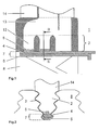
- FIG. 1 shows a section through the blade root 2 of such Turbine blade 1.
- the turbine blade 1 is inside with a Cooling system 13 equipped, which cooling air during the operation of the thermal turbo machine.
- the cooling air passes through Cooling ventilation holes 12, which are located on the blade base, into the cooling system 13. But this is generally from the prior art known and not shown in the figures.
- Disassembly of the turbine blade 1 from the axial groove, as in the Figure 1 is shown, is done by means of two sliders, one Hook slide 4 and a support slide 6.
- the hook slide 4 is in a gap 7, which is between the blade base and the Groove base is introduced.
- Hook 5, which is on the hook slide 4 are located, then engage in the cooling air holes 12 or in others Notches located in the blade base.
- the support slide 6 is inserted under the hook slide 4. This Support slide 6 connects positively to the hook slide 4 and provides the position assurance during the disassembly of the turbine blade 1 of the hook pusher 4 safely.
- FIG. 2 shows a corresponding section through the blade root 2 a turbine blade 1 according to the line II-II in Figure 1.
- the hook slider 4 and the one below it form-fitting connecting slide 6 and the hook 5 visible. Both are in the gap 7 below the blade root 2 between the Blade base of the turbine blade 1 and the groove base of the axial Groove 3.
- the disassembly of the turbine blade 1 according to the invention has been compared to the prior art Technology various advantages. Because there is an axial pull on the blade root 2 acts, become annoying moments that a tilting of the blade root effect, almost prevented. This is particularly because the Line of action of the attacking tensile force during disassembly according to the invention a target effective line is much closer than that of the previously known Technique known. The disassembly time decreases with the proposed procedures based on these facts significantly.
Landscapes
- Engineering & Computer Science (AREA)
- Mechanical Engineering (AREA)
- General Engineering & Computer Science (AREA)
- Turbine Rotor Nozzle Sealing (AREA)
Applications Claiming Priority (2)
| Application Number | Priority Date | Filing Date | Title |
|---|---|---|---|
| DE10020229A DE10020229A1 (de) | 2000-04-25 | 2000-04-25 | Verfahren und Vorrichtung zur Demontage einer Turbinenschaufel |
| DE10020229 | 2000-04-25 |
Publications (2)
| Publication Number | Publication Date |
|---|---|
| EP1149662A1 true EP1149662A1 (fr) | 2001-10-31 |
| EP1149662B1 EP1149662B1 (fr) | 2003-09-17 |
Family
ID=7639874
Family Applications (1)
| Application Number | Title | Priority Date | Filing Date |
|---|---|---|---|
| EP01108282A Expired - Lifetime EP1149662B1 (fr) | 2000-04-25 | 2001-04-02 | Procédé et dispositif de démontage d'une aube de turbine |
Country Status (3)
| Country | Link |
|---|---|
| US (1) | US6571471B2 (fr) |
| EP (1) | EP1149662B1 (fr) |
| DE (2) | DE10020229A1 (fr) |
Cited By (4)
| Publication number | Priority date | Publication date | Assignee | Title |
|---|---|---|---|---|
| DE10344098A1 (de) * | 2003-09-24 | 2005-04-21 | Alstom Technology Ltd Baden | Laufschaufel für eine Strömungsmaschine und zugehöriges Abziehwerkzeug |
| WO2007039396A1 (fr) * | 2005-10-06 | 2007-04-12 | Alstom Technology Ltd | Systeme d'aubes directrices d'une turbomachine |
| EP2169184A3 (fr) * | 2008-09-24 | 2013-04-24 | General Electric Company | Appareil et procédé pour l'extraction des segments d'aube de stator d'un compresseur de turbine à gaz avec le rotor en place |
| WO2017021074A1 (fr) * | 2015-08-06 | 2017-02-09 | Siemens Aktiengesellschaft | Procédé et dispositif d'expulsion d'aube |
Families Citing this family (14)
| Publication number | Priority date | Publication date | Assignee | Title |
|---|---|---|---|---|
| ES2346874T3 (es) | 2004-07-09 | 2010-10-21 | Siemens Aktiengesellschaft | Dispositivo para el desmontaje de palas de una turbina o de un compresor. |
| US8863365B2 (en) * | 2010-01-22 | 2014-10-21 | Siemens Energy, Inc. | Removal of stuck blade in a turbine engine |
| DE202010011921U1 (de) | 2010-08-27 | 2010-11-11 | Homburger Gmbh & Co. Kg | Demontagevorrichtung zur Demontage von Turbinenschaufeln |
| US8695216B2 (en) | 2011-12-27 | 2014-04-15 | Climax Portable Machine Tools, Inc. | Machine tools and methods for machining turbine rotor assemblies |
| EP2706198A1 (fr) * | 2012-09-10 | 2014-03-12 | Alstom Technology Ltd | Procédé pour supprimer un coffrage interne d'une machine |
| CN103707016B (zh) * | 2013-12-10 | 2016-09-21 | 中国南方航空工业(集团)有限公司 | 粉末高温合金涡轮盘榫槽的拉削加工方法 |
| US9494040B2 (en) | 2014-02-06 | 2016-11-15 | Siemens Energy, Inc. | Turbine engine blade removal apparatus and method |
| US9382801B2 (en) | 2014-02-26 | 2016-07-05 | General Electric Company | Method for removing a rotor bucket from a turbomachine rotor wheel |
| US9429041B2 (en) * | 2014-05-14 | 2016-08-30 | General Electric Company | Turbomachine component displacement apparatus and method of use |
| US9381602B2 (en) | 2014-05-14 | 2016-07-05 | General Electric Company | Turbomachine bucket displacement apparatus and method of use |
| US10273814B2 (en) | 2016-01-05 | 2019-04-30 | General Electric Company | Tool and method for installing turbomachine component |
| US10265838B2 (en) | 2016-03-28 | 2019-04-23 | General Electric Company | Removal tool |
| CN112253547B (zh) * | 2020-10-22 | 2022-11-18 | 湖南南方通用航空发动机有限公司 | 一种转子叶片的分解方法 |
| CN118024167B (zh) * | 2024-03-08 | 2024-09-10 | 重庆大唐国际武隆水电开发有限公司 | 一种大型轴流转桨式水轮机拆解装置 |
Citations (5)
| Publication number | Priority date | Publication date | Assignee | Title |
|---|---|---|---|---|
| US4141124A (en) * | 1977-08-29 | 1979-02-27 | United Technologies Corporation | Method and apparatus for removing one or more vanes from a gas turbine compressor stator |
| EP0013772A1 (fr) * | 1979-01-24 | 1980-08-06 | BBC Aktiengesellschaft Brown, Boveri & Cie. | Appareil pour démonter une pale du dernier disque d'un rotor |
| US4455730A (en) * | 1982-08-30 | 1984-06-26 | Westinghouse Electric Corp. | Turbine blade extractor |
| SU1611682A1 (ru) * | 1988-09-05 | 1990-12-07 | Предприятие П/Я А-3483 | Гидросъемник дл разборки ротора насоса |
| US5560841A (en) * | 1994-10-11 | 1996-10-01 | United Technologies Corporation | Stator vane extraction |
Family Cites Families (8)
| Publication number | Priority date | Publication date | Assignee | Title |
|---|---|---|---|---|
| DE294650C (fr) | ||||
| US4096614A (en) * | 1975-09-02 | 1978-06-27 | General Electric Company | Method and apparatus for removing stator vanes |
| US4078290A (en) * | 1976-11-08 | 1978-03-14 | Nasa | Stator rotor tools |
| US4400137A (en) * | 1980-12-29 | 1983-08-23 | Elliott Turbomachinery Co., Inc. | Rotor assembly and methods for securing a rotor blade therewithin and removing a rotor blade therefrom |
| FR2630951B1 (fr) * | 1988-05-03 | 1991-02-15 | Alsthom | Procede et dispositif pour l'extraction de paquets d'ailettes de turbine a vapeur |
| DD294650B5 (de) * | 1990-03-28 | 1996-03-21 | Abb Kraftwerke Berlin Gmbh | Verfahren zur Demontage von turbinenschaufeln mit steckfussverbindung |
| US5690469A (en) * | 1996-06-06 | 1997-11-25 | United Technologies Corporation | Method and apparatus for replacing a vane assembly in a turbine engine |
| US6375423B1 (en) * | 2000-12-26 | 2002-04-23 | General Electric Company | Method for removal of dovetailed turbine bucket from a turbine wheel |
-
2000
- 2000-04-25 DE DE10020229A patent/DE10020229A1/de not_active Withdrawn
-
2001
- 2001-04-02 EP EP01108282A patent/EP1149662B1/fr not_active Expired - Lifetime
- 2001-04-02 DE DE50100630T patent/DE50100630D1/de not_active Expired - Lifetime
- 2001-04-12 US US09/832,839 patent/US6571471B2/en not_active Expired - Lifetime
Patent Citations (5)
| Publication number | Priority date | Publication date | Assignee | Title |
|---|---|---|---|---|
| US4141124A (en) * | 1977-08-29 | 1979-02-27 | United Technologies Corporation | Method and apparatus for removing one or more vanes from a gas turbine compressor stator |
| EP0013772A1 (fr) * | 1979-01-24 | 1980-08-06 | BBC Aktiengesellschaft Brown, Boveri & Cie. | Appareil pour démonter une pale du dernier disque d'un rotor |
| US4455730A (en) * | 1982-08-30 | 1984-06-26 | Westinghouse Electric Corp. | Turbine blade extractor |
| SU1611682A1 (ru) * | 1988-09-05 | 1990-12-07 | Предприятие П/Я А-3483 | Гидросъемник дл разборки ротора насоса |
| US5560841A (en) * | 1994-10-11 | 1996-10-01 | United Technologies Corporation | Stator vane extraction |
Non-Patent Citations (1)
| Title |
|---|
| DATABASE WPI Derwent World Patents Index; AN 1991-309303 * |
Cited By (7)
| Publication number | Priority date | Publication date | Assignee | Title |
|---|---|---|---|---|
| DE10344098A1 (de) * | 2003-09-24 | 2005-04-21 | Alstom Technology Ltd Baden | Laufschaufel für eine Strömungsmaschine und zugehöriges Abziehwerkzeug |
| US7128537B2 (en) | 2003-09-24 | 2006-10-31 | Alstom Technology Ltd. | Rotor blade for a flow machine, and an associated pulling-off tool |
| WO2007039396A1 (fr) * | 2005-10-06 | 2007-04-12 | Alstom Technology Ltd | Systeme d'aubes directrices d'une turbomachine |
| US7674088B2 (en) | 2005-10-06 | 2010-03-09 | Alstom Technology Ltd. | Vane arrangement of a turbo machine |
| EP2169184A3 (fr) * | 2008-09-24 | 2013-04-24 | General Electric Company | Appareil et procédé pour l'extraction des segments d'aube de stator d'un compresseur de turbine à gaz avec le rotor en place |
| WO2017021074A1 (fr) * | 2015-08-06 | 2017-02-09 | Siemens Aktiengesellschaft | Procédé et dispositif d'expulsion d'aube |
| US10953526B2 (en) | 2015-08-06 | 2021-03-23 | Siemens Aktiengesellschaft | Method and drive-out device for driving out a blade |
Also Published As
| Publication number | Publication date |
|---|---|
| US20010032389A1 (en) | 2001-10-25 |
| EP1149662B1 (fr) | 2003-09-17 |
| DE50100630D1 (de) | 2003-10-23 |
| US6571471B2 (en) | 2003-06-03 |
| DE10020229A1 (de) | 2001-10-31 |
Similar Documents
| Publication | Publication Date | Title |
|---|---|---|
| EP1149662B1 (fr) | Procédé et dispositif de démontage d'une aube de turbine | |
| EP1614856B1 (fr) | Dispositif pour démonter une aube de turbine ou compresseur | |
| EP1541804B1 (fr) | Outil d'extraction d'aube de rotor | |
| DE69005845T2 (de) | Diaphragmaaufbau eines Verdichters. | |
| DE602004002049T2 (de) | Niederdruck-Turbine einer Turbomaschine | |
| DE10350627B4 (de) | Turbinenrotor- und Schaufelanordnung, Vorspannfedersegment und zugehöriges Verfahren für Dampfturbinenschaufeln der Reaktionsbauart | |
| EP2011963A1 (fr) | Turbine à gaz à poussée axiale compensée | |
| DE102009003833A1 (de) | Verfahren und System zur Demontage einer Maschine | |
| EP2320030B1 (fr) | Rotor et aube de rotor pour une turbomachine axiale | |
| DE102011055838B4 (de) | Gasturbinenleitapparat-Befestigung und Ausbau/Einbau-Verfahren | |
| DE4442157A1 (de) | Verfahren und Vorrichtung zur Beeinflussung des Radialspieles der Beschaufelung in axialdurchströmten Verdichtern | |
| EP3269943B1 (fr) | Turbine à gaz et procédé de protection d'une turbine à gaz en cas de rupture d'arbre | |
| DE4015732A1 (de) | Antriebsmaschinenanlage und verfahren zum umwandeln eines flugzeugtriebwerks in ein triebwerk fuer andere zwecke | |
| EP1703078B1 (fr) | Dispositif et procédé pour sécuriser les pattes de verrouillage dans un compresseur ou une turbine par pliage | |
| WO2009080439A1 (fr) | Plaque de protection contre l'érosion pour aubes mobiles | |
| DE19501811B4 (de) | Verfahren und Vorrichtung zur Messung des Schaufelspieles von thermischen Turbomaschinen | |
| DE19839592A1 (de) | Strömungsmaschine mit gekühlter Rotorwelle | |
| DE10357134A1 (de) | Rotor für einen Verdichter | |
| DE69110089T2 (de) | Reparaturweise von Turbinenschaufeln. | |
| DE19643336C2 (de) | Verfahren zum Demontieren des stirnseitigen Lagergehäuses oder ND-Verdichter-Wellenteiles eines Flugtriebwerkes | |
| DE60206292T2 (de) | Geschwindigkeitsbegrenzer für turbinen im lastfreien betrieb | |
| DE69525014T2 (de) | Abdeckstück zur Abdichtung des Raums zwischen Rotorstufen | |
| EP1512490B1 (fr) | Procédé de réparation d'une aube de turbomachine | |
| EP2206889A1 (fr) | Procédé de réduction de jeu des extrémités des aubes par un rotor déplaçable et turbine à gaz associée | |
| WO2001070451A1 (fr) | Procede permettant de demonter un element d'etancheite |
Legal Events
| Date | Code | Title | Description |
|---|---|---|---|
| PUAI | Public reference made under article 153(3) epc to a published international application that has entered the european phase |
Free format text: ORIGINAL CODE: 0009012 |
|
| AK | Designated contracting states |
Kind code of ref document: A1 Designated state(s): AT BE CH CY DE DK ES FI FR GB GR IE IT LI LU MC NL PT SE TR Kind code of ref document: A1 Designated state(s): DE GB |
|
| AX | Request for extension of the european patent |
Free format text: AL;LT;LV;MK;RO;SI |
|
| RAP1 | Party data changed (applicant data changed or rights of an application transferred) |
Owner name: ALSTOM (SWITZERLAND) LTD |
|
| RAP1 | Party data changed (applicant data changed or rights of an application transferred) |
Owner name: ALSTOM (SWITZERLAND) LTD |
|
| 17P | Request for examination filed |
Effective date: 20020408 |
|
| AKX | Designation fees paid |
Free format text: DE GB |
|
| 17Q | First examination report despatched |
Effective date: 20021129 |
|
| GRAH | Despatch of communication of intention to grant a patent |
Free format text: ORIGINAL CODE: EPIDOS IGRA |
|
| GRAS | Grant fee paid |
Free format text: ORIGINAL CODE: EPIDOSNIGR3 |
|
| GRAA | (expected) grant |
Free format text: ORIGINAL CODE: 0009210 |
|
| AK | Designated contracting states |
Kind code of ref document: B1 Designated state(s): DE GB |
|
| REG | Reference to a national code |
Ref country code: GB Ref legal event code: FG4D Free format text: NOT ENGLISH |
|
| REF | Corresponds to: |
Ref document number: 50100630 Country of ref document: DE Date of ref document: 20031023 Kind code of ref document: P |
|
| RAP2 | Party data changed (patent owner data changed or rights of a patent transferred) |
Owner name: ALSTOM TECHNOLOGY LTD |
|
| GBT | Gb: translation of ep patent filed (gb section 77(6)(a)/1977) |
Effective date: 20040104 |
|
| REG | Reference to a national code |
Ref country code: GB Ref legal event code: 732E |
|
| PLBE | No opposition filed within time limit |
Free format text: ORIGINAL CODE: 0009261 |
|
| STAA | Information on the status of an ep patent application or granted ep patent |
Free format text: STATUS: NO OPPOSITION FILED WITHIN TIME LIMIT |
|
| 26N | No opposition filed |
Effective date: 20040618 |
|
| REG | Reference to a national code |
Ref country code: DE Ref legal event code: R082 Ref document number: 50100630 Country of ref document: DE Representative=s name: ROESLER, UWE, DIPL.-PHYS.UNIV., DE Ref country code: DE Ref legal event code: R081 Ref document number: 50100630 Country of ref document: DE Owner name: GENERAL ELECTRIC TECHNOLOGY GMBH, CH Free format text: FORMER OWNER: ALSTOM TECHNOLOGY LTD., BADEN, CH Ref country code: DE Ref legal event code: R081 Ref document number: 50100630 Country of ref document: DE Owner name: ANSALDO ENERGIA IP UK LIMITED, GB Free format text: FORMER OWNER: ALSTOM TECHNOLOGY LTD., BADEN, CH |
|
| PGFP | Annual fee paid to national office [announced via postgrant information from national office to epo] |
Ref country code: DE Payment date: 20170419 Year of fee payment: 17 Ref country code: GB Payment date: 20170419 Year of fee payment: 17 |
|
| REG | Reference to a national code |
Ref country code: DE Ref legal event code: R082 Ref document number: 50100630 Country of ref document: DE Representative=s name: ROESLER, UWE, DIPL.-PHYS.UNIV., DE Ref country code: DE Ref legal event code: R081 Ref document number: 50100630 Country of ref document: DE Owner name: ANSALDO ENERGIA IP UK LIMITED, GB Free format text: FORMER OWNER: GENERAL ELECTRIC TECHNOLOGY GMBH, BADEN, CH |
|
| REG | Reference to a national code |
Ref country code: GB Ref legal event code: 732E Free format text: REGISTERED BETWEEN 20170824 AND 20170830 |
|
| REG | Reference to a national code |
Ref country code: DE Ref legal event code: R119 Ref document number: 50100630 Country of ref document: DE |
|
| GBPC | Gb: european patent ceased through non-payment of renewal fee |
Effective date: 20180402 |
|
| PG25 | Lapsed in a contracting state [announced via postgrant information from national office to epo] |
Ref country code: DE Free format text: LAPSE BECAUSE OF NON-PAYMENT OF DUE FEES Effective date: 20181101 |
|
| PG25 | Lapsed in a contracting state [announced via postgrant information from national office to epo] |
Ref country code: GB Free format text: LAPSE BECAUSE OF NON-PAYMENT OF DUE FEES Effective date: 20180402 |