EP0014122A1 - Hydromechanische Rutsch-Lenkungsvorrichtung - Google Patents
Hydromechanische Rutsch-Lenkungsvorrichtung Download PDFInfo
- Publication number
- EP0014122A1 EP0014122A1 EP80400047A EP80400047A EP0014122A1 EP 0014122 A1 EP0014122 A1 EP 0014122A1 EP 80400047 A EP80400047 A EP 80400047A EP 80400047 A EP80400047 A EP 80400047A EP 0014122 A1 EP0014122 A1 EP 0014122A1
- Authority
- EP
- European Patent Office
- Prior art keywords
- shaft
- planetary gear
- steering device
- hydromechanical
- crown
- Prior art date
- Legal status (The legal status is an assumption and is not a legal conclusion. Google has not performed a legal analysis and makes no representation as to the accuracy of the status listed.)
- Granted
Links
Images


Classifications
-
- B—PERFORMING OPERATIONS; TRANSPORTING
- B62—LAND VEHICLES FOR TRAVELLING OTHERWISE THAN ON RAILS
- B62D—MOTOR VEHICLES; TRAILERS
- B62D11/00—Steering non-deflectable wheels; Steering endless tracks or the like
- B62D11/02—Steering non-deflectable wheels; Steering endless tracks or the like by differentially driving ground-engaging elements on opposite vehicle sides
- B62D11/06—Steering non-deflectable wheels; Steering endless tracks or the like by differentially driving ground-engaging elements on opposite vehicle sides by means of a single main power source
- B62D11/10—Steering non-deflectable wheels; Steering endless tracks or the like by differentially driving ground-engaging elements on opposite vehicle sides by means of a single main power source using gearings with differential power outputs on opposite sides, e.g. twin-differential or epicyclic gears
- B62D11/14—Steering non-deflectable wheels; Steering endless tracks or the like by differentially driving ground-engaging elements on opposite vehicle sides by means of a single main power source using gearings with differential power outputs on opposite sides, e.g. twin-differential or epicyclic gears differential power outputs being effected by additional power supply to one side, e.g. power originating from secondary power source
- B62D11/18—Steering non-deflectable wheels; Steering endless tracks or the like by differentially driving ground-engaging elements on opposite vehicle sides by means of a single main power source using gearings with differential power outputs on opposite sides, e.g. twin-differential or epicyclic gears differential power outputs being effected by additional power supply to one side, e.g. power originating from secondary power source the additional power supply being supplied hydraulically
Definitions
- the present invention relates to the technical field of steering devices for vehicles and more particularly for vehicles with tracks or with non-steerable wheels, vehicles such as public works vehicles or battle tanks.
- An important problem posed by vehicles with tracks or with non-steerable wheels is to obtain a continuous variation in the turning radii when cornering.
- Another solution consists in adding to the hydrostatic direction hydrokinetic or purely mechanical devices which are used only in the most difficult cases of use.
- this provision requires the use of coupling devices such as clutches or dog clutch to allow the temporary grouping of these various elements when it is necessary to use all of the available power, for example in the case short cornering radii for which the power required for cornering is significant.
- the aim of the device according to the invention is to provide a continuous solution to the problem of variation of the turning radii of the vehicle, while avoiding the aforementioned drawbacks.
- the subject of the invention is therefore a hydromechanical steering device for vehicles with tracks or with non-steerable wheels allowing, under load, the continuous and smooth transition from hydraulic operation to hydro-mechanical operation, driven by a motor.
- the momentary immobilization device can be constituted by two free wheels mounted in opposition to the locking direction cooperating with immobilization means.
- the immobilization means then consist of two brakes with hydraulic, electromagnetic, or mechanical control.
- the hydrostatic transmission of the hydromechanical device may comprise at least one hydraulic circuit comprising one or more pumps and one or more hydraulic motors, the displacement of each of these elements being able to be fixed or variable, each pump being driven by the first shaft transmission and the output shaft of each motor driving the central wheel of the first planetary gear via a gear train.
- variable displacement element can be controlled by the vehicle's steering wheel, either directly or by means of any intermediate mechanical, electrical or hydraulic device.
- the clutch device is composed of an intermediate shaft carrying a pinion connecting it to the first transmission shaft and two sets of discs, and by two clutch receivers, these two clutches being able to be controlled independently. one from the other, the two shafts coupled by the clutch device having substantially the same speed of rotation, at the time of coupling.
- Each clutch receiver is connected to the shaft carrying the central wheel of the second planetary gear, the first receiver being connected to it by an even number and the second by an odd number of intermediate gears.
- the freewheels mounted in opposition are composed of two internal rings arranged on the shaft carrying the planet carrier arms of the first planetary gear train and the crown of the second planetary gear train and of two external rings cooperating with the means immobilization.
- the hydrostatic transmission is split, which implies a different arrangement of the members constituting the steering device.
- the hydrostatic transmission comprises two identical hydraulic circuits.
- Each of the pumps is driven by the first transmission shaft which further carries two toothed wheels and each motor drives each of the ends of a second intermediate shaft which drives the central wheel of the first planetary gear via a gear train .
- the second planetary gear train comprises a double satellite connected to two central wheels, each of these central wheels driving a shaft which carries at each of these ends a clutch receiver.
- the set of discs of each of these clutches is carried by a hollow half-shaft driven in rotation by each toothed wheel of the first transmission shaft, the first and the second half-shaft being driven respectively by means of an even number and of an odd number of intermediate gears.
- the crown of the second planetary gear train cooperates by means of a gear train with the momentary immobilization device, the latter being carried by a hollow shaft concentric with the second intermediate shaft.
- the shaft carrying the crown of the first planetary gear train drives in opposite directions the central wheels of two output epicycles, the crowns of which cooperate with the gearbox and the planet carrier arms of which drive the wheels driving.
- the two devices defined above have their first transmission shaft connected to the heat engine by an inverter and are characterized in that the pump of each hydrostatic transmission is rotated downstream of the inverter so that the vehicle is turned in the direction of rotation of the steering wheel, in forward, and in the opposite direction in reverse, which allows to keep the same trajectory.
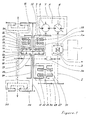
- FIG 1 schematically shows the first embodiment briefly described above and Figure 2 the second embodiment.
- Figure 3 shows on the ordinate a possible example of the variations in the displacement of the hydraulic transmission pump as well as the braking and clutch application ranges of the device as a function of the position (on the abscissa) of the steering wheel from its position median to its stop position.
- a rotation to the right of the steering wheel will correspond to the positive abscissa part of the curves while a rotation to the left of the steering wheel will correspond to their negative abscissa part.
- FIG. 1 therefore shows a hydromechanical steering device used on a vehicle comprising a heat engine 1 which can be associated with a torque converter or a clutch and transmitting its power to a first drive shaft 2 via a reverse gear 4, comprising a double bevel gear 3 and 3a.
- a heat engine 1 which can be associated with a torque converter or a clutch and transmitting its power to a first drive shaft 2 via a reverse gear 4, comprising a double bevel gear 3 and 3a.
- the first transmission shaft drives at one of its ends the rotation of the variable displacement pump 6 of a hydraulic transmission 5.
- This also consists of a hydraulic circuit 7 which allows the pump 6 to flow into a motor hydraulic 8.
- the latter drives the central wheel 13 of the first planetary gear train, by means of a gear train here represented by the gears 9 and 10.
- the latter train is disposed at one end of a hollow shaft 11 mounted on the 'output shaft 12 of the steering device.
- the hollow shaft carries at its second end the aforementioned central wheel 13.
- the epicyclic double train 14 is arranged so that the arm 15, which carries the satellites 16 of the first train, is connected to the crown 17 of the second train.
- the arm 18 carrying the satellites 19 of the second train is connected to the crown 20 of the first train.
- the speed of rotation of the planet carrier shaft of each planetary gear train is equal to that of the crown of the other train.
- the shaft 21 carrying the satellites 16 of the first train and the crown 17 of the second train is a hollow shaft arranged around the shaft 11 and, of course, having the same axis of rotation as the tree 12.
- the double planetary gear 14 cooperates with the momentary immobilization device 22 by means of the aforementioned shaft 21. Indeed the latter carries the internal rings of two free wheels 23 and 24 mounted in opposition to the locking direction and belonging to the immobilizing device 22. The latter is completed by two brakes cooperating with the outer rings of the two freewheels 23 and 24.
- the device 22 thus makes it possible to make the position of the crown 17 of the second planetary gear train fixed, and the arm 15 of the first train or make it possible according to the chosen operation, the rotation of these in one direction or the other.
- the locking and unlocking control of each of the brakes 25 and 26 is fixed by the position of the vehicle steering wheel.
- the double planetary gear 14 cooperates with the first transmission shaft 2 by means of the clutch device 27.
- the clutch device 27 comprises, as can be seen in FIG. 1, two clutches 31 and 32, the disks of which are mounted on an intermediate shaft 28 coupled by a gear train 29, 30 to the first transmission shaft 2.
- the two clutch receivers 31 and 32 are linked to the central wheel 33 of the second planetary gear with a hollow shaft 34 concentric with the shaft 12 and an even and odd number of gears respectively, which makes it possible to drive in one way or the other the rotation of the central wheel of the second train.
- the two clutches 31 and 32 are controlled by any appropriate means by the position of the steering control wheel.
- each of the two clutches can only be tightened when the two parts then coupled (respectively one of the receivers of the clutches 31 and 32 of the shaft 28) have approximately equal speed.
- the pump 6 does not rotate and the two brakes 25 and 26 are applied if the steering wheel is in the middle position ("straight line” position). Due to this position of the steering wheel, the two clutches 31 and 32 are free.
- the vehicle is then in neutral.
- the drive shaft 2 rotates in a determined direction and rotates in the same direction h pump 6.
- the flywheel is always in the middle position, the pump is at zero flow and the hydraulic motor 8 can't turn.
- the vehicle can then be moved in a straight line exclusively and entirely mechanically.
- the displacement of the pump 6 and the direction of circulation of the fluid in the circuit 7 are controlled so that by passing the flywheel from its middle position to its abutment position, the displacement of the pump 6 passes from the zero value to a maximum to decrease then until the zero value then increase again with an invention of the direction of circulation of fluid in the circuit 7 as it appears on figure 3.
- the curve located at the bottom of the figure shows a possible variation mode of the displacement of the pump.
- the negative displacement will represent the variation of the displacement when it is accompanied by the change of direction of fluid circulation in the circuit 7.
- the curve is shown here by way of example, the important points being those of zero and maximum displacement, the variation between these points being a function of the control device chosen in practice.
- the upper part of the curve shows in solid lines with reference to the brakes 25 and 26 and the clutches 31 and 32 the tightening ranges of these various elements as a function of variations in the displacement of the pump and the rotational movements of the flywheel .
- the hydraulic motor 8 starts to rotate as does the central wheel 13 of the first planetary gear.
- the planet carrier arm 15 being immobilized by one of the brakes 25 or 26, the rotation of the central wheel 13 causes that of the planet carrier arm 18 of the second planetary gear train and therefore that of the steering shaft 12.
- the flywheel corresponds the maximum displacement of the pump-6.
- the kinematics of the device is such that at this position also corresponds an equalization of the speeds of the shaft 28 and that of the two clutches which rotates in the same direction as the shaft 28 with however a slight advance with respect to the latter.
- the central wheel 33 of the second planetary gear train then rotates in the direction of the shaft 12 while the central wheel of the first planetary gear train rotates in the opposite direction imposed on it by the direction of rotation of the motor 8, which serves as a support mobile and becomes a receiver.
- the speed of rotation of the latter is fixed by the displacement of the pump 6.
- the motor 8 and the central wheel 13 tend to come to a stop, which accelerates the shaft 12 and therefore the pivoting speed of the vehicle.
- the engine speed 8 increases with the displacement of the pump 6, and the central wheel 13 of the first train accelerates its rotation, in the same direction as the shaft 12, and again the pivoting speed increases.
- the pivoting is stopped by returning the steering wheel to its neutral position regardless of its previous position.
- the turning radius will depend only on the momentary displacement of the pump, the direction of rotation of the motor 8 of the application of the various brakes and clutches .
- the device according to the invention can be arranged according to a second embodiment, the particulars of which will be specified below, in relation to FIG. 2.
- the second embodiment of the invention will include two symmetrical hydraulic transmissions 5 and 5a.
- variable displacement hydraulic pump (6 and 6a) is disposed on each end of the first transmission shaft, each delivering a motor with a fixed displacement (respectively 8 and 8a).
- the two motors 8 and 8a are then connected together by a second intermediate shaft 46 which transmits its hydraulic power to the central wheel 13 of the first planetary gear via a gear train 9, 10 and the shaft hollow 11 carrying the central wheel.
- the mechanical power coming from the heat engine and passing through the clutches 31 and 32, is transmitted to the double planetary gear from the shaft 2 by two gear trains, one containing an even number (respectively 39.40) and the another an odd number (respectively 41, 42 and 43) of gears.
- the wheels 40 and 43 are carried by two hollow half-shafts 44 and 45 concentric with the shaft 12 and supporting the discs of the clutches 31 and 32 whose receivers are also carried by two other hollow half-shafts concentric with the shaft 12 and supporting central wheels 33a and 33b.
- the second planetary gear train is double in the sense that it includes a double central wheel (33a and 33b), double satellites (19 a and 19 b) carried by the planet carrier arm 18.
- the duplication of the second train allows then a better distribution of the forces on the various elements constituting it.
- the double planetary gear 14 cooperates by means of a gear train with the device 22 for momentary immobilization which is arranged for reasons of convenience on a hollow shaft carried by the second intermediate shaft 46.
- This arrangement interposing a gear between the double train 14 and the device 22 makes it possible to adapt to the capacity of the brakes 25 and 26 and of the free wheels 23 and 24 making up the latter, the large torque transmitted by the planet carrier arm 15.
- the mechanical elements are coupled under load, smoothly, automatically by the presence of the free wheels and without slippage, which avoids wasted power and therefore improves efficiency compared with prior art.
Landscapes
- Engineering & Computer Science (AREA)
- Chemical & Material Sciences (AREA)
- Combustion & Propulsion (AREA)
- Transportation (AREA)
- Mechanical Engineering (AREA)
- Non-Deflectable Wheels, Steering Of Trailers, Or Other Steering (AREA)
Applications Claiming Priority (2)
| Application Number | Priority Date | Filing Date | Title |
|---|---|---|---|
| FR7900923A FR2446756A1 (fr) | 1979-01-16 | 1979-01-16 | Dispositif de direction hydro-mecanique |
| FR7900923 | 1979-01-16 |
Publications (2)
| Publication Number | Publication Date |
|---|---|
| EP0014122A1 true EP0014122A1 (de) | 1980-08-06 |
| EP0014122B1 EP0014122B1 (de) | 1982-04-07 |
Family
ID=9220772
Family Applications (1)
| Application Number | Title | Priority Date | Filing Date |
|---|---|---|---|
| EP19800400047 Expired EP0014122B1 (de) | 1979-01-16 | 1980-01-14 | Hydromechanische Rutsch-Lenkungsvorrichtung |
Country Status (3)
| Country | Link |
|---|---|
| EP (1) | EP0014122B1 (de) |
| DE (1) | DE3060261D1 (de) |
| FR (1) | FR2446756A1 (de) |
Cited By (9)
| Publication number | Priority date | Publication date | Assignee | Title |
|---|---|---|---|---|
| EP0058666A4 (de) * | 1980-09-02 | 1984-04-27 | Caterpillar Tractor Co | Lenkungs-planetendifferentialgetriebe. |
| EP0102049A3 (en) * | 1982-08-26 | 1984-09-12 | General Electric Company | Simplified hydromechanical steering transmission |
| WO1984003675A1 (en) * | 1983-03-14 | 1984-09-27 | Caterpillar Tractor Co | Vehicle steering differential |
| WO1986007324A1 (fr) * | 1985-06-15 | 1986-12-18 | Zahnradfabrik Friedrichshafen Ag | Systeme de direction a recouvrement pour vehicules a chenilles |
| EP0145724B1 (de) * | 1983-03-25 | 1988-05-25 | A.B. Volvo | Planetengetriebe |
| WO1989003335A1 (fr) * | 1987-10-09 | 1989-04-20 | Zahnradfabrik Friedrichshafen Ag | Boite de direction superposee pour vehicules a chenilles |
| EP0982170A4 (de) * | 1997-05-14 | 2002-10-24 | Yanmar Agricult Equip | Antiebseinheit für raupenfahrzeug |
| RU2392163C1 (ru) * | 2009-01-11 | 2010-06-20 | Юрий Феликсович Черняков | Пропашной гусеничный трактор |
| US7993230B2 (en) | 2008-05-06 | 2011-08-09 | Deere & Company | Dual path hydromechanical powertrain |
Families Citing this family (1)
| Publication number | Priority date | Publication date | Assignee | Title |
|---|---|---|---|---|
| FR3058702B1 (fr) | 2016-11-17 | 2018-11-02 | Nexter Systems | Train de roulement pour vehicule chenille, vehicule chenille incorporant un tel train de roulement et procede de conversion d'un vehicule a roues en vehicule chenille |
Citations (3)
| Publication number | Priority date | Publication date | Assignee | Title |
|---|---|---|---|---|
| US3373636A (en) * | 1965-09-27 | 1968-03-19 | Gen Motors Corp | Vehicle transmission including steering by driving |
| DE1929380A1 (de) * | 1969-06-10 | 1970-12-23 | Zahnradfabrik Friedrichshafen | UEberlagerungslenkgetriebe fuer Gleiskettenfahrzeuge |
| US3575066A (en) * | 1969-09-23 | 1971-04-13 | Gen Motors Corp | Transmission |
-
1979
- 1979-01-16 FR FR7900923A patent/FR2446756A1/fr active Granted
-
1980
- 1980-01-14 EP EP19800400047 patent/EP0014122B1/de not_active Expired
- 1980-01-14 DE DE8080400047T patent/DE3060261D1/de not_active Expired
Patent Citations (3)
| Publication number | Priority date | Publication date | Assignee | Title |
|---|---|---|---|---|
| US3373636A (en) * | 1965-09-27 | 1968-03-19 | Gen Motors Corp | Vehicle transmission including steering by driving |
| DE1929380A1 (de) * | 1969-06-10 | 1970-12-23 | Zahnradfabrik Friedrichshafen | UEberlagerungslenkgetriebe fuer Gleiskettenfahrzeuge |
| US3575066A (en) * | 1969-09-23 | 1971-04-13 | Gen Motors Corp | Transmission |
Non-Patent Citations (1)
| Title |
|---|
| INGENIEURS DE L'AUTOMOBILE, No. 1, Janvier 1979, M.P. LEBOIME "Techniques des transmissions des vehicules chenilles rapides", pages 28-35. * |
Cited By (11)
| Publication number | Priority date | Publication date | Assignee | Title |
|---|---|---|---|---|
| EP0058666A4 (de) * | 1980-09-02 | 1984-04-27 | Caterpillar Tractor Co | Lenkungs-planetendifferentialgetriebe. |
| EP0102049A3 (en) * | 1982-08-26 | 1984-09-12 | General Electric Company | Simplified hydromechanical steering transmission |
| WO1984003675A1 (en) * | 1983-03-14 | 1984-09-27 | Caterpillar Tractor Co | Vehicle steering differential |
| US4557157A (en) * | 1983-03-14 | 1985-12-10 | Caterpillar Tractor Co. | Vehicle steering differential |
| EP0145724B1 (de) * | 1983-03-25 | 1988-05-25 | A.B. Volvo | Planetengetriebe |
| WO1986007324A1 (fr) * | 1985-06-15 | 1986-12-18 | Zahnradfabrik Friedrichshafen Ag | Systeme de direction a recouvrement pour vehicules a chenilles |
| WO1989003335A1 (fr) * | 1987-10-09 | 1989-04-20 | Zahnradfabrik Friedrichshafen Ag | Boite de direction superposee pour vehicules a chenilles |
| US5041064A (en) * | 1987-10-09 | 1991-08-20 | Zahnradfabrik Friedrichshafen Ag | Superimposed steering gear for tracklaying vehicles |
| EP0982170A4 (de) * | 1997-05-14 | 2002-10-24 | Yanmar Agricult Equip | Antiebseinheit für raupenfahrzeug |
| US7993230B2 (en) | 2008-05-06 | 2011-08-09 | Deere & Company | Dual path hydromechanical powertrain |
| RU2392163C1 (ru) * | 2009-01-11 | 2010-06-20 | Юрий Феликсович Черняков | Пропашной гусеничный трактор |
Also Published As
| Publication number | Publication date |
|---|---|
| FR2446756B1 (de) | 1982-07-02 |
| DE3060261D1 (en) | 1982-05-19 |
| EP0014122B1 (de) | 1982-04-07 |
| FR2446756A1 (fr) | 1980-08-14 |
Similar Documents
| Publication | Publication Date | Title |
|---|---|---|
| FR2497735A1 (fr) | Systeme d'entrainement d'un vehicule | |
| WO2006125876A1 (fr) | Boite de vitesses a double embrayage | |
| EP0014122B1 (de) | Hydromechanische Rutsch-Lenkungsvorrichtung | |
| WO1991013275A1 (fr) | Dispositif de transmission a rapport variable, en particulier pour l'automobile | |
| CA1142776A (fr) | Transmission hydromecanique comportant eventuellement un coupleur hydrocinetique d'appoint en particulier pour direction de vehicules chenilles | |
| FR3013273A1 (fr) | Groupe motopropulseur pour l'entrainement d'un vehicule automobile, plus particulierement pour un vehicule de type hybride. | |
| FR3100755A1 (fr) | Chaîne de transmission électrique pour véhicule automobile | |
| FR3021594A1 (fr) | Dispositif de transmission de vitesse pour le deplacement d'un vehicule automobile, notamment d'un vehicule motorise a deux-roues. | |
| FR2598195A1 (fr) | Boite de vitesses automatique a trains planetaires. | |
| FR2723777A1 (fr) | Train de transmission de puissance d'une transmission automatique pour vehicule | |
| EP0026115B1 (de) | Hydrostatische Getriebe mit grossem Betriebsbereich | |
| FR2587077A1 (fr) | Appareil de changement d'entrainement en marche avant-arriere et transmission le comportant | |
| FR2702814A1 (fr) | Transmission automatique à vitesse variable. | |
| WO2016066331A1 (fr) | Dispositif de transmission de vitesse pour le déplacement d'un véhicule automobile, notamment d'un véhicule motorisé à au moins deux roues, et groupe motopropulseur utilisant un tel dispositif | |
| EP0013190B1 (de) | Hydraulische Antriebsgruppe für ein Fahrzeug mit mechanischer Leistungsverzweigung beim Lenken | |
| EP0359654A1 (de) | Antrieb für schnelle Raupenfahrzeuge oder Fahrzeuge mit nichtgelenkten Rädern | |
| FR2698144A1 (fr) | Boîte de vitesses munie de trois transmissions partielles à trains planétaires. | |
| FR3071576B1 (fr) | Dispositif de transmission de vitesse avec marche arriere pour le deplacement d'un vehicule automobile, notamment d'un vehicule motorise a au moins deux-roues | |
| FR2597184A1 (fr) | Convertisseur de couple a etage-multiple et trois-elements | |
| FR3029854A1 (fr) | Groupe motopropulseur pour l'entrainement d'un vehicule automobile avec un dispositif de transmission a variation de vitesse a double train epicycloidal et en particulier groupe motopropulseur pour un vehicule de type hybride. | |
| FR2679975A1 (fr) | Transmission hydromecanique pour vehicules automobiles. | |
| EP0633181B1 (de) | Kraftfahrzeuglenkung durch Herbeiführen eines Geschwindigkeitsunterschiedes zwischen rechts- und linksseitigen Rädern | |
| FR3083583A1 (fr) | Transmission pour véhicule | |
| WO2008050010A2 (fr) | Transmission a derivation de puissance et blocage de l'arbre d'entree de la transmission entraine par le moteur thermique d'un vehicule | |
| FR3144239A1 (fr) | Mécanisme de transmission à au moins deux rapports de vitesses |
Legal Events
| Date | Code | Title | Description |
|---|---|---|---|
| PUAI | Public reference made under article 153(3) epc to a published international application that has entered the european phase |
Free format text: ORIGINAL CODE: 0009012 |
|
| AK | Designated contracting states |
Designated state(s): DE |
|
| 17P | Request for examination filed | ||
| DET | De: translation of patent claims | ||
| GRAA | (expected) grant |
Free format text: ORIGINAL CODE: 0009210 |
|
| AK | Designated contracting states |
Designated state(s): DE |
|
| REF | Corresponds to: |
Ref document number: 3060261 Country of ref document: DE Date of ref document: 19820519 |
|
| PGFP | Annual fee paid to national office [announced via postgrant information from national office to epo] |
Ref country code: DE Payment date: 19981218 Year of fee payment: 20 |
|
| PLBE | No opposition filed within time limit |
Free format text: ORIGINAL CODE: 0009261 |
|
| STAA | Information on the status of an ep patent application or granted ep patent |
Free format text: STATUS: NO OPPOSITION FILED WITHIN TIME LIMIT |