EP0014231A1 - Datenspeichervorrichtung - Google Patents
Datenspeichervorrichtung Download PDFInfo
- Publication number
- EP0014231A1 EP0014231A1 EP79104184A EP79104184A EP0014231A1 EP 0014231 A1 EP0014231 A1 EP 0014231A1 EP 79104184 A EP79104184 A EP 79104184A EP 79104184 A EP79104184 A EP 79104184A EP 0014231 A1 EP0014231 A1 EP 0014231A1
- Authority
- EP
- European Patent Office
- Prior art keywords
- assembly
- hda
- disk
- casing
- spindle
- Prior art date
- Legal status (The legal status is an assumption and is not a legal conclusion. Google has not performed a legal analysis and makes no representation as to the accuracy of the status listed.)
- Granted
Links
Images


Classifications
-
- G—PHYSICS
- G11—INFORMATION STORAGE
- G11B—INFORMATION STORAGE BASED ON RELATIVE MOVEMENT BETWEEN RECORD CARRIER AND TRANSDUCER
- G11B25/00—Apparatus characterised by the shape of record carrier employed but not specific to the method of recording or reproducing, e.g. dictating apparatus; Combinations of such apparatus
- G11B25/04—Apparatus characterised by the shape of record carrier employed but not specific to the method of recording or reproducing, e.g. dictating apparatus; Combinations of such apparatus using flat record carriers, e.g. disc, card
-
- G—PHYSICS
- G11—INFORMATION STORAGE
- G11B—INFORMATION STORAGE BASED ON RELATIVE MOVEMENT BETWEEN RECORD CARRIER AND TRANSDUCER
- G11B5/00—Recording by magnetisation or demagnetisation of a record carrier; Reproducing by magnetic means; Record carriers therefor
- G11B5/48—Disposition or mounting of heads or head supports relative to record carriers ; arrangements of heads, e.g. for scanning the record carrier to increase the relative speed
- G11B5/54—Disposition or mounting of heads or head supports relative to record carriers ; arrangements of heads, e.g. for scanning the record carrier to increase the relative speed with provision for moving the head into or out of its operative position or across tracks
- G11B5/55—Track change, selection or acquisition by displacement of the head
- G11B5/5521—Track change, selection or acquisition by displacement of the head across disk tracks
-
- G—PHYSICS
- G11—INFORMATION STORAGE
- G11B—INFORMATION STORAGE BASED ON RELATIVE MOVEMENT BETWEEN RECORD CARRIER AND TRANSDUCER
- G11B19/00—Driving, starting, stopping record carriers not specifically of filamentary or web form, or of supports therefor; Control thereof; Control of operating function ; Driving both disc and head
- G11B19/20—Driving; Starting; Stopping; Control thereof
-
- G—PHYSICS
- G11—INFORMATION STORAGE
- G11B—INFORMATION STORAGE BASED ON RELATIVE MOVEMENT BETWEEN RECORD CARRIER AND TRANSDUCER
- G11B23/00—Record carriers not specific to the method of recording or reproducing; Accessories, e.g. containers, specially adapted for co-operation with the recording or reproducing apparatus ; Intermediate mediums; Apparatus or processes specially adapted for their manufacture
- G11B23/02—Containers; Storing means both adapted to cooperate with the recording or reproducing means
- G11B23/021—Containers; Storing means both adapted to cooperate with the recording or reproducing means comprising means for reducing influence of physical parameters, e.g. temperature change, moisture
-
- G—PHYSICS
- G11—INFORMATION STORAGE
- G11B—INFORMATION STORAGE BASED ON RELATIVE MOVEMENT BETWEEN RECORD CARRIER AND TRANSDUCER
- G11B25/00—Apparatus characterised by the shape of record carrier employed but not specific to the method of recording or reproducing, e.g. dictating apparatus; Combinations of such apparatus
- G11B25/08—Apparatus characterised by the shape of record carrier employed but not specific to the method of recording or reproducing, e.g. dictating apparatus; Combinations of such apparatus using filamentary record carriers, e.g. wire
Definitions
- the invention relates to information storage apparatus and is more particularly concerned with magnetic disk storage apparatus of the type which comprise two major assemblies, a head disk assembly (HDA) and a drive assembly which together form a magnetic disk file for the storage of data in a data processing system.
- the head disk assembly is arranged relative to the drive assembly so that it may be replaced in the field without disruption to the remaining disk storage devices which are connected to the data processing system.
- the HDA is arranged with the disks in a horizontal plane so that the disk spindle is vertical.
- the HDA is positioned on a substantially horizontal baseplate with the disk spindle extending above the baseplate.
- the baseplate is provided with suitable reference surfaces for the HDA to insure that the axis of the voice coil motor is coaxial with the annular flux gaps of the VCM, which is also attached to the baseplate.
- the above type disk files employing HDAs are characterized primarily by the magnetic transducers being permanently associated with corresponding disk surfaces, as distinguished from earlier files employing removable dis! 5 paons.
- the disk pacKs merely conaisted 01 a stack of magnetic disks and the magnetic head carriage assembly and the actuator were permanently associated with the drive portion oi the file.
- the coil of the voice coil motor which furetions to position the magnetic heads to an addressed data track, is permanently associated with the voice coil mctor of the drive, and means are provided to automatically couple an extension from the coil to the head carriage assembly when the Data Module is placed on the drive.
- the Data Module and its associated drive are constructed such that the replacement of the Data Module can be readily accomplished by an unskilled operator, which permits the user to maintain a substantial amount of data offline and, when a particular set of data is required, merely to place that Data Module into the system, much like the use of prior ar disk packs.
- the HDA as described therein, is constructed such that the coil of the VCM is permanently associated with the HDA, and apparatus which was on the drive to assist the operator in automatically loading the Data Module has been eliminated from the drive portion of the combination.
- the HDA is still replaceable and the design intent is to make the HDA field replaceable by a service engineer, rather than an operator.
- An added advantage of such an arrangement is obtained in manufacturing such a file since the HDA assembly contains substantially all of the close tolerance mechanical parts of the file and is generally manufactured in a "clean room" type of environment.
- the remaining portion of the drive involves components which can be assembled in more conventional type electronic assembly environments.
- Access time generally comprises the period it takes the voice coi motor or actuator to peri0rr a seek operation, that is, to move a magnetic head from the
- Seek times are on the order of 20 to 30 milliseconds in present commercial files, which is still relatively long compared to the time it takes the file to read or write a given record.
- the system performance can generally be improved if two separate actuators could be provided, each having access to half the amount of data since the seek operations can then be overlapped, thereby reducing the waiting time for the data processing system to the data required to perform its operation.
- the only available option for a user where system throughput is limited by seek times, is to add additional files, since that is the only available manner to obtain additional access operations at the current level of access times and magnetic recording densities. This involves more cost for storage and requires more physical space to house the installation.
- the present invention avoids the above-described dismantling problem by providing a compact HDA-drive configuration in which the HDA employs two separate independently operated head carriage assemblies, each of which is associated with a different set of disks and are moved independently of each other by the actuator which is mounted on the drive assembly of the file.
- the disks are mounted on a common shaft and disposed vertically in the HDA.
- the use of two separate actuators to access data on a given number of disk surfaces allows the track density of each set of disk surfaces to be increased because smaller carriages can be employed which permits more precise control of the head-arm assemblies associated with each carriage.
- the drive portion comprises a baseplate having a generally U-shaped cross-section in the front portion so as to accommodate the lower portion of the HDA, which surrounds the bottom half of the vertically arranged disks.
- the U-shaped front portion is open to accommodate the lower section of the HDA as it is inserted into the drive in the horizontal direction.
- the upper edges of the front portion of the U-shaped baseplate are designed to provide means for referencing the HDA to the actuator structure which is mounted on an integral rear platform of the baseplate, thereby allowing the spindle drive motor to be mounted under the flat rear portion of the baseplate which mounts the actuator.
- the bottom of the U-shaped front portion extends generally upward to the leading edge of the rear plat-form to provide adequate space for the spindle motor, and to provide additional strength to the baseplate.
- the motor is pivotally mounted to the bottom of the rear platform of the baseplate with its axis parallel to the disk spindle.
- the motor is tupled to the disk spindle by means of a pair oi pulleys and a drivebelt which lie in a plane perpendicular to the disk spindle and motor shaft.
- the opposite side of the motor shaft drives the blower for the air supply system.
- the components of the air supply system such as the absolute filter and ducting from the filter to the HDA, are packaged below the baseplate. The relative placement of all of the above components contributes to a small, compact disk file arrangement.
- the carriages of the HDA are positioned so that the transducers move along a pair of parallel axes which extend normal to the disk shaft and lie in a plane substantially parallel to the referencing plane established by the upp 2 r edges of the U-shaped baseplate.
- the carriages are positioned between the disk spindle axis and the actuator of the drive, which permits the HDA to be loaded into its operating position by movement of the HDA in a horizontal direction parallel to these axes.
- Such an arrangement permits the HDA to be operatively positioned on the drive by adjusting only a minimum number of components on the drive assembly, such as the electrical connections to the HDA and the drive belt.
- the invention provides information storage apparatus comprising a housing assembly and an information storage sub assembly disengageable mounted in an operative position in the housing assembly, characterised in that the sub assembly comprises a horizontal spindle journalled in a rigid disc casing to rotate about a horizontal axis and carrying magnetic storage disc means having recording surfaces extending in parallel vertical planes, first and second magnetic head means in transducing relationship with first and second vertical recording surfaces of the magnetic disc means, first and second carriages respectively supporting the first and second head means and being independently mounted on the casing for movement along parallel predetermined paths tu carry the head means to different radial positions relative to the disc surfaces with which they are in transducing relationship, and first and second electrically energisable armature means forming parts of first and second electromagnetic actuator means effective in operation ro reciprocate said first and second carriages independently oi each other along their predetermined paths, the remaining parts of said first and second actuator means being mounted on said housing assembly.
- Another object of the present invention is to provide, for a compact disc file of the HDA-drive configuration type, HDA assembly in which there are two carriages, the carriages moving independently along spaced parallel paths extending normal to the disk spindle and disposed on the same side oi the spindle.
- the invention also provides an information storage sub assembly for disengageable mounting in vertically orientated operative position in a housing assembly to constitute therewith a magnetic disc information storage apparatus, said sub-assembly comprising a spindle journalled In a rigid dise casing to rotate about a horizontal axis and carrying magnetic storage disc means having recording surfaces extending in parallel planes orthogonal to the axis cf the spindle, first and second magnetic head means in transducing relationship with first and second recording surfaces of the magnetic disc means, first and second carriages respectively supporting the first and second head means and being independently mounted on the casing for movement along parallel predetermined paths to carry the head means to different radial positions relative to the disc surfaces with which they are in transducing relationship and first and second electrically energisable armature means forming parts of first and second electromagnetic actuator means effective in operation to reciprocate said first and second carriages independently of each other along their predetermined paths, the remaining parts of said first and second actuator means being provided on the housing assembly with which the sub-assembl
- a further object of the present invention is to provide for a compact dish file of the HDA-drive configuration type, a drive assembly characterised by a U-shaped baseplate for supporting the HDA with the bottom half of the HDA which surrounds the vertical disks disposed within the U-shaped baseplate.
- the invention further provides a housing assembly for providing a disengageable mounting for an information storage sub assembly as aforesaid, said housing assembly comprising a base plate including integral front and rear portions and being characterised in that the fron portion is of U-shaped channel form such that the lower portion of a vertically orientated disc casing fits between ie side walls of the channel and in that the front end of the channel is open to permit passage through the open front end of the lower portion of the casing during horizontal movement of the disc casing to engage it with and dis-engage it from, the housing assembly.
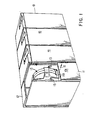
- Figure 1 illustrates a string of four disk drives 10, each of which embody the present invention.
- the front cover 11 and top 12 of disk drive 10A have been broken away to show the HDA 13 and the front portion 14A of the U-shaped baseplate.
- the baseplate is attached by means of shock mount 17 to suitable frame members 15 which extend around the perimeter of the baseplate and to which the covers of the machine are attached.
- the HDA 13 is removed from file 10A by sliding the HDA 13 relative to the front portion 14A of the baseplate in a horizontal plane in a direction normal to the front cover, as indicated by arrow 16.
- Figure 2 illustrates in greater detail the major components of the disk file shown in Figure 1.
- the drive comprises the HDA assembly 13 and the U-shaped baseplate 14, along with the components of the air supply system 20 and the voice coil motor 21.
- the components of the HDA 13 and their arrangement will first be described in connection with Figures 2 through 4B.
- the HDA comprises generally a frame member 23 which, in the preferred embodiment, consists of two portions 23A and 23B which substantially surround a plurality of magnetic disks 24, the outlines of two disks being shown in d otted line form.
- the disks are mounted in spaced relationship on a disk spindle (not shown) whose axis 25 extends in a substantially horizontal plane.
- Each frame portion 23A and 23B is provided with a disk spindle bearing to support the disk spindle shaft. Only one bearing, 26B, is shown in Figures 2 and 3. The other bearing, 26A (not shown), is positioned correspondingly in frame member 23A.
- the frame members 23A and 23B may be assembled in a suitable fixture which insures that the disk spindle axis 25 is normal to the bearings 26A and 26B in both halves of the HDA frame.
- a pair of dowl pins 30 and 31 may be employed to maintain the accurately machined frame in position relative to each other.
- Dowl pin 30 at the bottom of the HDA ( Figure 3) and dowl pin 31 (shown in Figure 2) align both halves 26A and 26B of the HDA together.
- a dowl pin slot 33 ( Figure 2) associated with dowl pin 31 provides a degree of movement between the two halves to facilitate insertion of the dowl pins.
- the HDA further includes a pair of transducer carriage and way assemblies 37A and 37B which are shown removed from the HDA to expose the way portions of the assembly.
- the carriage and way assemblies 37A and 37B shown are similar to that described in U.S. Patent 3,838,455, and may be employed in the present arrangement to achieve the function of positioning different sets of magnetic transducers relative to different sets of disks 24 on the spindle shaft.
- each carriage assembly is attached to its respective frame member 13 such that the axis 41 of the way lies in a plane common to the axis 25 of the disk spindle shoft and is normal to the shaft axis 25.
- the axes 41 of the round ways arc, therefore, parallel to each other and function to cause the respective carriages 37 to move along parallel spaced paths.
- each L-shaped and, as described in U.S. Patent 3,838,455 carry a group of arm assemblies, each of which includes a pair of transducers 38 for cooperating with one surface of one magnetic disk 24.
- Attached to the side of each L-shaped carriage opposite to the head-arms is an extension 44 for attaching an annul.ar coil 45 which is adapted to be inserted in a corresponding annular flux gap of the voice coil actuator, which is mounted on a platform of the U-shaped baseplate and which will be described in detail later in the specification.
- the HDA 13 is further provided with suitable means for referencing the HDA assembly to the drive assembly so that the coils 45A and 45B relate in an operative manner with the magnetic structure which is permanently attached to the drive assembly.
- the referencing means comprises a pair of feet 50 and 51 (not shown) and a locator pin 53 which cooperates with a reference guide 54 and reference cone 55 ( Figure 5) on the drive assembly.
- the function of these reference feet and guide is similar to the function of the guide shown in Figures 2 and 2A of U.S. Patent 4,034,411.
- the function of the locator pin 53 and the reference cone 55 is similar to the function of the arrangement shown in Figure 3A of U.S. Patent 4,034,411.
- Other referencing arrangements known in the art may also be employed.
- each head-arm assembly also includes the flexible cable 42 which is attached to a printed circuit board 55 ( Figure 4B) mounted to the front panel 43 which will now be described in connection with
- FIG 4A Prior to leaving Figure 3, it should be noted that the HDA is also provided with a narrow air inlet port 66 towards the bottom of the frame members, whose function will be described in connection with Figures 5 and 6 and the air flow system of the disk file.
- the front panel 43 as shown in Figures 4A and 4B, has the same general configuration as the opening 60 into the HDA and is attached thereto by means of bolts 67.
- the panel 43 may be made of aluminum and is provided with two generally rectangular openings 72 and 73. Opening 72 defines an air exhaust port for the HDA and mates with suitable ducting structure on The drive assembly. Opening 73 is partially covered by magnetic shield plate 74 which abuts the magnetic structure on the drive.
- the shield 74 is made in two pieces in order to position openings 75 around the extensions 44 of the coil support member attached to the carriages 37.
- Terminal block 76 is for signals to the transducers and blocks 77 and 78 for supplying signals to the coils from the drive. Blocks 77 and 78 mate automatically with complementary terminal block 79 on the drive when the HDA is in its operative position. Terminal block 76 is connected with a flexible cable 80 from the drive electronics.
- FIG. 5 illustrates primarily the details of the U-shaped baseplate 14 and the mounting of the voice coil motor structure 21.
- baseplate 14 has a front portion 14A having a generally U-shaped cross-section.
- the rear portion 14B can also have a U-shaped cross-section, but of a considerable lesser depth, so that a plate 14C is provided for the magnet structure 21.
- the bottom of the U-shaped front section 14A is joined to the leading edge of the platform portion 14C by the section 14D.
- the baseplate is cast so that all of the portions referred to above are integral, as shown in outline form in Figure 6.
- the baseplate 14 is provided with suitable shock mounts 81 which mount the baseplate to the machine frame 82.
- Figure 5 illustrates in more detail the referencing means on the baseplate which cooperate with the referencing means on the HDA to properly align the two assemblies.
- guide blocks 54 and the reference cone block 55 provide a suitable referencing means.
- the magnet structure 21 shown in Figure 5 comprises a dual actuator voice coil motor.
- separate voice coil magnet structures may be employed to cooperate with the coils 45A and 45B of the HDA assembly.
- the oval shaped front edge of the magnet structure 21 is provided with a suitable gasket 84 which seals the HDA assembly 15 to this surface and allows air being dxhausted from the HDA to also cool the coils 45 in the two annular flux gaps formed by center pole pieces 85.
- the baseplate is provided with a downward extending motor mount 86 on each side of the rear portion 14B of the baseplate to allow the motor for the disk spindle to be pivotally mounted with its axis parallel to the axis 25 of the disk spindle when the HDA assembly 13 is registered on the disk drive assembly.
- the mounting of the motor beneath the rear platform 14C of the baseplate contributes to a relatively low overall height of the disk file.
- a suitable pulley belt system 87 couples the disk spindle shaft to the motor shaft.
- the motor 88 is spring biased about its pivotal axis 89 by spring 90 to permit insertion of the belt 91 over the front pulley 92 when the HDA is being attached to the drive assembly.
- the spring 90 also maintains the HDA 13 through the belt system 87 biased against the reference cone 55. If additional biasing force is required for the HDA 13, any suitable external biasing arrangement known in the art may be employed.
- Figure 7 also shows the system associated with the drive assembly for supplying contaminant free air to the HDA assembly and for returning air therefrom.
- the system when operational, is basically a closed loop system, although an open loop system may be employed if desired.
- one function of the air supply system is to maintain the disks, head-arm assemblies, baseplate, and carriages at a substantially constant temperature relative to one another. This becomes quite important where track densities are above 500 tracks to the inch and a dedicated servo surface is employed in position control of the accessing system. If different disks 24 are not subject to the same temperature, the tendency is for tracks in the same cvlinder to be offset relative to each other since they experience different amounts of thermal expansion. The placement of the disks 24 in a vertical plane permits a more even exposure to the incoming air stream and provides a much more uniform. temperature throughout the HDA relative to the HDA assemblies where the disks rotate in parallel horizontal planes.
- an impeller (not shown) for the blower 93 is provided with a conventional scroll shaped housing.
- the output of the blower 93 is connected to the air input port 66 of the HDA 13 by means of duct 94 which includes the absolute filter 95 and a suitable nozzle type member 96.
- Duct 94 and nozzle 96 and the absolute filter 95 may be arranged to move slightly during pivotal movement of the motor or a flexible joint 97, as shown in Figure 6, may be employed between the fixed nozzle 96 and the movable housing 93 since the blower impeller is attached directly to the shaft of pivotal motor 88.
- Duct 97 which can also be seen in Figure 2, extends from the opening 72 in the HDA, defined by the cover plate 43.
- a suitable seal 99 is provided to seal duct 97 to the HDA.
- Return duct 98 extends from the bottom of the magnet structure 21 through an opening in the baseplate 14, as shown in Figure 7, and into the side of duct 97.
- Duct 97 is attached to the center of the blower housing 93 by means of a bellows to accommodate movement of the casing 93 relative to the stationary duct 97 when the motor 88 is pivoted.
- the absolute filter 95 shown in Figures 6 and 7, disposed in duct 94 between the output of the blower and the input nozzle 96, is to provide contaminant free air to the HDA.
- Figure 8 is an illustration to show the relationship of the various axes and reference planes which exist when the HDA assembly is properly inserted in the disk drive assembly.
- Axis 25 represents the disk spindle which is in a horizontal plane.
- the disks 24 are spaced along this axis so that their surfaces are normal to the axis 25 and perpendicular to plane B.
- the hearing members 26B are coaxial with axis 25 and lie in planes C and D, parallel to the disk surfaces.
- the round way axes 41 are parallel to each other and interseci the disk axis 25 at 90! and lie in a plane B, which is horizontal.
- the reference means on the drive in cooperation with the reference means on the HDA, establish the shaft axis 25 in horizontal plane with the pin-cone arrangemen T insuring that the way members are also in this horizontal plane.
- the yawing motion about an axis normal to the horizontal plane is controlled by the spacing between the guide blocks 54 on the baseplate 14 and the feet 50 on the HDA 13.
- Axes FF and GG correspond to the axis of the annular flux gap or center pole magnets 85 and are coaxial with the axes of the associated coils 45. These axes are at the center mass of the respective carriage assemblies 37, which tends to reduce any bending movements being introduced into the carriage assemblies 37 during rapid acceleration and deceleration periods.
- Axis 89 represents the axis of the motor about which it is pivoted and axis KK represents the axis of the shaft of motor 88. These axes are parallel to the disk spindle axis 25, allowing the pulley drive belt system 87 to be positioned in a plane normal to both the spindle axis and the motor axis KK.
- the two separate carriages 37 and the magnet structure 21 on ⁇ he drive assembly involve the coil-flux gap interface.
- This coil-flux gap interface could be modified in accordance with the teachings of U.S. Patent 3,853,415 (Barnard et al) assigned to the assignee of the present invention. In such a modification, the coils 45 would be then permanently associated with the VCM 21 and an extension from each carriage 37 would be coupled to an extension of the coils 45, as shown in the above-mentioned patent.
- a suitable braking system could be employed to decelerate the rotating disks when power is turned of on the disk drive 10.
Landscapes
- Moving Of Heads (AREA)
- Automatic Disk Changers (AREA)
- Indexing, Searching, Synchronizing, And The Amount Of Synchronization Travel Of Record Carriers (AREA)
- Exchange Systems With Centralized Control (AREA)
Applications Claiming Priority (2)
| Application Number | Priority Date | Filing Date | Title |
|---|---|---|---|
| US6404 | 1979-01-25 | ||
| US06/006,404 US4285018A (en) | 1979-01-25 | 1979-01-25 | Disk file |
Publications (2)
| Publication Number | Publication Date |
|---|---|
| EP0014231A1 true EP0014231A1 (de) | 1980-08-20 |
| EP0014231B1 EP0014231B1 (de) | 1983-02-02 |
Family
ID=21720693
Family Applications (1)
| Application Number | Title | Priority Date | Filing Date |
|---|---|---|---|
| EP79104184A Expired EP0014231B1 (de) | 1979-01-25 | 1979-10-29 | Datenspeichervorrichtung |
Country Status (14)
| Country | Link |
|---|---|
| US (1) | US4285018A (de) |
| EP (1) | EP0014231B1 (de) |
| JP (2) | JPS5818707B2 (de) |
| KR (1) | KR830000896B1 (de) |
| BR (1) | BR8000313A (de) |
| CA (1) | CA1135409A (de) |
| DE (1) | DE2964674D1 (de) |
| DK (1) | DK151741C (de) |
| ES (1) | ES487973A1 (de) |
| FI (1) | FI76218C (de) |
| IL (1) | IL58851A (de) |
| NO (1) | NO155166C (de) |
| NZ (1) | NZ192223A (de) |
| ZA (1) | ZA797058B (de) |
Cited By (4)
| Publication number | Priority date | Publication date | Assignee | Title |
|---|---|---|---|---|
| US4359762A (en) * | 1980-05-13 | 1982-11-16 | Stollorz Herbert R | Removable storage module and module |
| EP0064731A1 (de) * | 1981-05-07 | 1982-11-17 | Siemens Aktiengesellschaft | Plattenkassette für Datenspeichergerät |
| EP0109678A1 (de) * | 1982-11-19 | 1984-05-30 | Microscience International Corporation | Kompaktes Plattenspeichersystem mit hoher Aufzeichnungsdichte |
| EP0222939A1 (de) * | 1985-10-31 | 1987-05-27 | International Business Machines Corporation | Plattenspeicher mit einem in die Nabe des Plattenstapels integrierten Antriebsmotor |
Families Citing this family (15)
| Publication number | Priority date | Publication date | Assignee | Title |
|---|---|---|---|---|
| JPS5823362A (ja) * | 1981-07-30 | 1983-02-12 | Nippon Telegr & Teleph Corp <Ntt> | 揺動アクチユエ−タ |
| FR2521386A1 (fr) * | 1982-02-11 | 1983-08-12 | Cii Honeywell Bull | Systeme de ventilation d'une cartouche pour disque(s) magnetique(s) amovible(s) et cartouche ventilee par ce systeme |
| JPS59223984A (ja) * | 1983-05-31 | 1984-12-15 | Fujitsu Ltd | 磁気デイスク装置 |
| US4642715A (en) * | 1984-11-01 | 1987-02-10 | Miltope Corporation | Environmental conditioning and safety system for disk-type mass memories |
| US4639863A (en) * | 1985-06-04 | 1987-01-27 | Plus Development Corporation | Modular unitary disk file subsystem |
| US4860194A (en) * | 1985-06-04 | 1989-08-22 | Plus Development Corporation | A method for using a modular unitary disk file subsystem |
| US4780776A (en) * | 1987-04-20 | 1988-10-25 | International Business Machines Corporation | Air flow system in a data recording disk file |
| US4835637A (en) * | 1987-09-08 | 1989-05-30 | International Business Machines Corporation | Disk file with in-hub motor |
| US5041924A (en) * | 1988-11-30 | 1991-08-20 | Quantum Corporation | Removable and transportable hard disk subsystem |
| JP2553316B2 (ja) * | 1993-03-02 | 1996-11-13 | インターナショナル・ビジネス・マシーンズ・コーポレイション | データ記憶ディスク・ドライブ装置 |
| DE4330051C2 (de) * | 1993-09-06 | 1997-01-23 | Wilfried Restle | Verfahren und Anordnung zur signifikanten Erhöhung der Lebensdauer und Aufzeichnungsdichte von Magnetplattenspeichern |
| US6697214B2 (en) | 2001-04-26 | 2004-02-24 | International Business Machines Corporation | Removable disk drive with separable electrical and mechanical components |
| US7535670B2 (en) * | 2003-02-21 | 2009-05-19 | Seagate Technology Llc | Flow or windage control for a cantilevered head assembly |
| US7729083B2 (en) * | 2006-02-09 | 2010-06-01 | Hitachi Global Storage Technologies Netherlands B.V. | Hermetically sealed head disk assembly |
| US8411387B2 (en) | 2009-01-21 | 2013-04-02 | Seagate Technology Llc | Injecting processing fluid while writing data |
Citations (4)
| Publication number | Priority date | Publication date | Assignee | Title |
|---|---|---|---|---|
| US3725883A (en) * | 1969-10-03 | 1973-04-03 | Burroughs Corp | Modular disk file unit |
| GB1379396A (en) * | 1970-12-21 | 1975-01-02 | Sperry Rand Corp | Magnetic disc storage assembly |
| US4034411A (en) * | 1975-07-11 | 1977-07-05 | International Business Machines Corporation | Magnetic disk information storage apparatus |
| US4136293A (en) * | 1977-11-07 | 1979-01-23 | International Business Machines Corporation | Multi-actuator system using single magnetic circuit |
Family Cites Families (12)
| Publication number | Priority date | Publication date | Assignee | Title |
|---|---|---|---|---|
| US3825951A (en) * | 1970-02-06 | 1974-07-23 | Kogyo Gijutsuin | Magnetic disc memory |
| US3740735A (en) * | 1970-09-14 | 1973-06-19 | Diablo Systems Inc | Air circulation apparatus |
| BE791363A (fr) * | 1971-11-15 | 1973-05-14 | Xerox Corp | Dispositifs de compensation thermique pour unite de memoire a disque |
| US3973273A (en) * | 1971-12-10 | 1976-08-03 | International Business Machines Corporation | Magnetic disk storage apparatus |
| DE2257946C3 (de) * | 1972-11-25 | 1981-07-23 | Basf Ag, 6700 Ludwigshafen | Behälter für einen scheibenförmigen Aufzeichnungsträger und ein Antriebsgerät zu seiner Verwendung |
| US3838455A (en) * | 1973-03-05 | 1974-09-24 | Ibm | Head carriage assembly for magnetic disk storage apparatus |
| US3938192A (en) * | 1974-02-11 | 1976-02-10 | Information Storage Systems, Inc. | Method of manufacturing a spindle assembly for a disc drive |
| US3886595A (en) * | 1974-02-13 | 1975-05-27 | Information Storage Systems | Actuator for a disc drive apparatus |
| US3912278A (en) * | 1974-07-22 | 1975-10-14 | Int Memory Systems | Disk drive assembly |
| US4092687A (en) * | 1976-09-07 | 1978-05-30 | Sycor, Inc. | Disc file assembly |
| US4130845A (en) * | 1977-07-08 | 1978-12-19 | Microdata Corporation | Disc cabinet recirculating air flow system |
| US4166284A (en) * | 1978-07-21 | 1979-08-28 | Daniels Kenneth M | Read/write head-positioning apparatus |
-
1979
- 1979-01-25 US US06/006,404 patent/US4285018A/en not_active Expired - Lifetime
- 1979-10-03 JP JP54126930A patent/JPS5818707B2/ja not_active Expired
- 1979-10-29 EP EP79104184A patent/EP0014231B1/de not_active Expired
- 1979-10-29 DE DE7979104184T patent/DE2964674D1/de not_active Expired
- 1979-11-13 CA CA000339711A patent/CA1135409A/en not_active Expired
- 1979-11-23 NZ NZ192223A patent/NZ192223A/xx unknown
- 1979-11-30 KR KR1019790004226A patent/KR830000896B1/ko not_active Expired
- 1979-12-03 IL IL58851A patent/IL58851A/xx unknown
- 1979-12-28 ZA ZA00797058A patent/ZA797058B/xx unknown
-
1980
- 1980-01-17 BR BR8000313A patent/BR8000313A/pt not_active IP Right Cessation
- 1980-01-17 NO NO800113A patent/NO155166C/no unknown
- 1980-01-21 FI FI800160A patent/FI76218C/fi not_active IP Right Cessation
- 1980-01-24 DK DK030480A patent/DK151741C/da not_active IP Right Cessation
- 1980-01-24 ES ES487973A patent/ES487973A1/es not_active Expired
-
1981
- 1981-11-20 JP JP56185619A patent/JPS57111862A/ja active Granted
Patent Citations (5)
| Publication number | Priority date | Publication date | Assignee | Title |
|---|---|---|---|---|
| US3725883A (en) * | 1969-10-03 | 1973-04-03 | Burroughs Corp | Modular disk file unit |
| GB1379396A (en) * | 1970-12-21 | 1975-01-02 | Sperry Rand Corp | Magnetic disc storage assembly |
| US4034411A (en) * | 1975-07-11 | 1977-07-05 | International Business Machines Corporation | Magnetic disk information storage apparatus |
| US4136293A (en) * | 1977-11-07 | 1979-01-23 | International Business Machines Corporation | Multi-actuator system using single magnetic circuit |
| DE2847393A1 (de) * | 1977-11-07 | 1979-05-10 | Ibm | Linearer schwingspulmotor |
Cited By (4)
| Publication number | Priority date | Publication date | Assignee | Title |
|---|---|---|---|---|
| US4359762A (en) * | 1980-05-13 | 1982-11-16 | Stollorz Herbert R | Removable storage module and module |
| EP0064731A1 (de) * | 1981-05-07 | 1982-11-17 | Siemens Aktiengesellschaft | Plattenkassette für Datenspeichergerät |
| EP0109678A1 (de) * | 1982-11-19 | 1984-05-30 | Microscience International Corporation | Kompaktes Plattenspeichersystem mit hoher Aufzeichnungsdichte |
| EP0222939A1 (de) * | 1985-10-31 | 1987-05-27 | International Business Machines Corporation | Plattenspeicher mit einem in die Nabe des Plattenstapels integrierten Antriebsmotor |
Also Published As
| Publication number | Publication date |
|---|---|
| JPS6120073B2 (de) | 1986-05-20 |
| IL58851A (en) | 1982-07-30 |
| ES487973A1 (es) | 1980-09-16 |
| JPS57111862A (en) | 1982-07-12 |
| ZA797058B (en) | 1980-11-26 |
| NO155166C (no) | 1987-02-18 |
| FI76218C (fi) | 1988-09-09 |
| DE2964674D1 (en) | 1983-03-10 |
| JPS55101171A (en) | 1980-08-01 |
| NO155166B (no) | 1986-11-10 |
| DK151741B (da) | 1987-12-28 |
| NZ192223A (en) | 1983-06-17 |
| EP0014231B1 (de) | 1983-02-02 |
| NO800113L (no) | 1980-07-28 |
| DK151741C (da) | 1988-06-13 |
| DK30480A (da) | 1980-07-26 |
| CA1135409A (en) | 1982-11-09 |
| JPS5818707B2 (ja) | 1983-04-14 |
| FI76218B (fi) | 1988-05-31 |
| IL58851A0 (en) | 1980-03-31 |
| KR830000896B1 (ko) | 1983-04-26 |
| FI800160A7 (fi) | 1980-07-26 |
| US4285018A (en) | 1981-08-18 |
| BR8000313A (pt) | 1980-09-23 |
Similar Documents
| Publication | Publication Date | Title |
|---|---|---|
| EP0014231A1 (de) | Datenspeichervorrichtung | |
| US5081552A (en) | Rigid magnetic disk drive head disk assembly and enclosure structure | |
| US3849800A (en) | Magnetic disc apparatus | |
| EP0287768A2 (de) | Luftumwälzsystem bei einem Plattenstapel zur Aufzeichnung von Daten | |
| US4150406A (en) | Transducer lifting means employing plural flexures | |
| US6097608A (en) | Disk drive vibration isolation using diaphragm isolators | |
| US4034411A (en) | Magnetic disk information storage apparatus | |
| US5986852A (en) | High capacity, high performance low profile disk drive | |
| KR940022535A (ko) | 디스크 드라이브용 구조체 및 외피 조립체 | |
| JPH0628647A (ja) | 多重トラック方式のテープレコーダ用ヘッド位置合わせ機構 | |
| US6898048B2 (en) | Plenum assembly which filters multiple fluidic current channels using a single recirculation filter | |
| JP2690579B2 (ja) | 光ディスク装置 | |
| JP4355118B2 (ja) | ディスク装置 | |
| US5060095A (en) | Head-disk enclosure assembly for a magnetic disk storage device | |
| JPH04265589A (ja) | コンパクトディスクドライブ | |
| EP0361783A2 (de) | Plattenspeicher mit symmetrischem Gehäuse | |
| JP3375259B2 (ja) | 磁気ディスク装置 | |
| US4967296A (en) | Lightweight, rigid, compact configuration for the voice coil, carriage and printed circuit cable in a disc drive | |
| US4263629A (en) | Disk file with symmetrical hollow base | |
| JP2006108324A (ja) | 電子装置 | |
| AU593472B2 (en) | Thermal isolation of the voice coil motor from base plate and carriage guide rails of a disc drive | |
| US7468867B2 (en) | Disk apparatus having a narrow magnetic gap | |
| JP3688445B2 (ja) | 磁気ディスク装置 | |
| JP2656671B2 (ja) | フロッピィディスク装置 | |
| EP1111592B1 (de) | Magnetiches Aufnahmegerät |
Legal Events
| Date | Code | Title | Description |
|---|---|---|---|
| PUAI | Public reference made under article 153(3) epc to a published international application that has entered the european phase |
Free format text: ORIGINAL CODE: 0009012 |
|
| AK | Designated contracting states |
Designated state(s): BE CH DE FR GB IT NL SE |
|
| 17P | Request for examination filed | ||
| ITF | It: translation for a ep patent filed | ||
| GRAA | (expected) grant |
Free format text: ORIGINAL CODE: 0009210 |
|
| AK | Designated contracting states |
Designated state(s): BE CH DE FR GB IT NL SE |
|
| REF | Corresponds to: |
Ref document number: 2964674 Country of ref document: DE Date of ref document: 19830310 |
|
| ET | Fr: translation filed | ||
| PGFP | Annual fee paid to national office [announced via postgrant information from national office to epo] |
Ref country code: FR Payment date: 19900926 Year of fee payment: 12 |
|
| PGFP | Annual fee paid to national office [announced via postgrant information from national office to epo] |
Ref country code: SE Payment date: 19901005 Year of fee payment: 12 |
|
| PGFP | Annual fee paid to national office [announced via postgrant information from national office to epo] |
Ref country code: DE Payment date: 19901027 Year of fee payment: 12 |
|
| ITTA | It: last paid annual fee | ||
| PGFP | Annual fee paid to national office [announced via postgrant information from national office to epo] |
Ref country code: NL Payment date: 19901031 Year of fee payment: 12 |
|
| PGFP | Annual fee paid to national office [announced via postgrant information from national office to epo] |
Ref country code: GB Payment date: 19910923 Year of fee payment: 13 |
|
| PG25 | Lapsed in a contracting state [announced via postgrant information from national office to epo] |
Ref country code: SE Effective date: 19911030 |
|
| PGFP | Annual fee paid to national office [announced via postgrant information from national office to epo] |
Ref country code: BE Payment date: 19911107 Year of fee payment: 13 |
|
| PGFP | Annual fee paid to national office [announced via postgrant information from national office to epo] |
Ref country code: CH Payment date: 19920128 Year of fee payment: 13 |
|
| PG25 | Lapsed in a contracting state [announced via postgrant information from national office to epo] |
Ref country code: NL Effective date: 19920501 |
|
| NLV4 | Nl: lapsed or anulled due to non-payment of the annual fee | ||
| PG25 | Lapsed in a contracting state [announced via postgrant information from national office to epo] |
Ref country code: FR Effective date: 19920630 |
|
| PG25 | Lapsed in a contracting state [announced via postgrant information from national office to epo] |
Ref country code: DE Effective date: 19920701 |
|
| REG | Reference to a national code |
Ref country code: FR Ref legal event code: ST |
|
| PG25 | Lapsed in a contracting state [announced via postgrant information from national office to epo] |
Ref country code: GB Effective date: 19921029 |
|
| PG25 | Lapsed in a contracting state [announced via postgrant information from national office to epo] |
Ref country code: CH Effective date: 19921031 Ref country code: BE Effective date: 19921031 |
|
| BERE | Be: lapsed |
Owner name: INTERNATIONAL BUSINESS MACHINES CORP. Effective date: 19921031 |
|
| GBPC | Gb: european patent ceased through non-payment of renewal fee |
Effective date: 19921029 |
|
| REG | Reference to a national code |
Ref country code: CH Ref legal event code: PL |
|
| EUG | Se: european patent has lapsed |
Ref document number: 79104184.1 Effective date: 19920510 |
|
| PLBE | No opposition filed within time limit |
Free format text: ORIGINAL CODE: 0009261 |
|
| STAA | Information on the status of an ep patent application or granted ep patent |
Free format text: STATUS: NO OPPOSITION FILED WITHIN TIME LIMIT |