EP0014271B1 - Vorrichtung und Verfahren zum Überwachen des Schweissens - Google Patents
Vorrichtung und Verfahren zum Überwachen des Schweissens Download PDFInfo
- Publication number
- EP0014271B1 EP0014271B1 EP79200765A EP79200765A EP0014271B1 EP 0014271 B1 EP0014271 B1 EP 0014271B1 EP 79200765 A EP79200765 A EP 79200765A EP 79200765 A EP79200765 A EP 79200765A EP 0014271 B1 EP0014271 B1 EP 0014271B1
- Authority
- EP
- European Patent Office
- Prior art keywords
- welding
- integrating
- electrodes
- seam
- voltage
- Prior art date
- Legal status (The legal status is an assumption and is not a legal conclusion. Google has not performed a legal analysis and makes no representation as to the accuracy of the status listed.)
- Expired
Links
- 238000000034 method Methods 0.000 title claims abstract description 28
- 238000012544 monitoring process Methods 0.000 title claims abstract description 13
- 238000003466 welding Methods 0.000 claims abstract description 65
- 230000008569 process Effects 0.000 claims abstract description 13
- 230000007246 mechanism Effects 0.000 claims description 6
- 238000004519 manufacturing process Methods 0.000 description 11
- 230000002950 deficient Effects 0.000 description 3
- 230000004048 modification Effects 0.000 description 3
- 238000012986 modification Methods 0.000 description 3
- 238000012360 testing method Methods 0.000 description 3
- 229910000831 Steel Inorganic materials 0.000 description 2
- 239000002184 metal Substances 0.000 description 2
- 239000010959 steel Substances 0.000 description 2
- ATJFFYVFTNAWJD-UHFFFAOYSA-N Tin Chemical compound [Sn] ATJFFYVFTNAWJD-UHFFFAOYSA-N 0.000 description 1
- 230000008859 change Effects 0.000 description 1
- 238000007796 conventional method Methods 0.000 description 1
- 230000007547 defect Effects 0.000 description 1
- 230000007812 deficiency Effects 0.000 description 1
- 238000013461 design Methods 0.000 description 1
- 238000010586 diagram Methods 0.000 description 1
- 230000000694 effects Effects 0.000 description 1
- 235000013305 food Nutrition 0.000 description 1
- 238000010438 heat treatment Methods 0.000 description 1
- 230000000977 initiatory effect Effects 0.000 description 1
- 239000007788 liquid Substances 0.000 description 1
- 230000004044 response Effects 0.000 description 1
- 230000001960 triggered effect Effects 0.000 description 1
Images

Classifications
-
- B—PERFORMING OPERATIONS; TRANSPORTING
- B23—MACHINE TOOLS; METAL-WORKING NOT OTHERWISE PROVIDED FOR
- B23K—SOLDERING OR UNSOLDERING; WELDING; CLADDING OR PLATING BY SOLDERING OR WELDING; CUTTING BY APPLYING HEAT LOCALLY, e.g. FLAME CUTTING; WORKING BY LASER BEAM
- B23K11/00—Resistance welding; Severing by resistance heating
- B23K11/24—Electric supply or control circuits therefor
- B23K11/25—Monitoring devices
Definitions
- This invention relates to the control of welding apparatus by measuring the voltage across the electrodes. More specifically, the apparatus of the invention and the method of its use are directed towards the control of resistance welding apparatus in which overlapping metal seams are welded together by the application of electric power via rollers concurrently with the application of pressure.
- the invention has general applicability to many applications of welding of this type; however, the invention will be described specifically as related to the manufacture of cans for the containing of liquids or foods or other products inasmuch as that is the application for which the invention was first developed.
- the manufacture of cans is at present commercially accomplished in a variety of ways.
- One of the more common methods is to roll a sheet of flat steel, ordinarily coated on both sides with a thin layer of tin, into a cylinder and weld up the resulting seam.
- the edges of the steel sheet are overlapped slightly to form the seam.
- This weld can be performed in a variety of ways. Possibly the most common is through resistance welding, where the can is passed between a pair of electrically energized rollers, thus causing a current to flow between the overlapped edges forming the seam. If pressure is applied to the rollers, they essentially flatten out the overlapping edges so that the cylinder thus formed is essentially uniform in wall thickness around its circumference. Ends may then be applied to the can by conventional techniques.
- Another object of the invention is to provide a method for monitoring welds as they are made.
- Yet another object of the present invention is to provide a method whereby continuous seam welds of cans can be monitored as the cans are being welded.
- a further object of the invention is to provide a weld monitoring method which is capable of monitoring each individual stitch in a stitch welding application.
- an object of the present invention is to provide a method and apparatus whereby the weld performed on cans may be monitored during the welding operation and associated apparatus and a method for removing poorly welded cans from the production line, based on the monitoring results, without operator intervention.
- the present invention satisfies the needs of the art and the objects listed above by its provision of at least one integrating voltmeter, used in conjunction with a blanking pulse generator, to measure the voltage developed across the welding electrodes which in turn is used to indicate the integrity of each weld, and to use the output of this voltmeter to provide an error signal which will remove poorly welded cans from the production line.
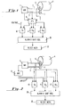
- Fig. 1 is a schematic representation of apparatus which is suitable for the practice of the process of the invention.
- a welding machine 1 such as the Soudronic unit described above, supplies current to a can to be welded 4 via arms 2 and 3 on which are carried current rollers 6 and 7.
- the can 4 is welded by passing it between rollers 6 and 7.
- Welding machine 1 is provided with suitable internal circuitry and external timing devices so that when a can's position between roller electrodes 6 and 7 is detected, a signal is fed to the machine to activate it.
- the welding machine is activated, passing current via arms 2 and 3 through the rollers 6 and 7 and into the edges of the sheet forming the can thus welding the seam.
- the welding current the thickness of the metal to be welded; the electrical conductivity between the arms 2 and 3, the rollers 6 and 7, and the pressure of the rollers 6 and 7 on can 4; the surface condition of the rollers 6 and 7 and of the can 4; the inductance of the entire system including the welding generator; and the timing of the can and its speed through the rollers.
- the welding parameters desirable for the proper welding of cans vary from one end of the seam to the other. Specifically, the beginning of the can, the center of the can, and the end of the can are frequently to be welded at, for example, different current settings.
- the present invention solves this problem by providing a blanking pulse generator used in combination with a number, preferably 3, of such integrating voltmeters: one each for the beginning, for the middle, and for the end of the seam.
- Fig. 1 As discussed above, current passes from welding machine 1 through arms 2 and 3 and rollers 6 and 7 to the seam to be welded of can 4. An internal signal indicating the start of the welding operation is taken from the welding machine and passed into blanking pulse generator 8; a voltage signal is taken off rollers 6 and 7. These signals are passed to the blanking pulse generator 8 which amounts, in this embodiment, to a switching device.
- the blanking pulse generator sends the voltage signals on to one of integrating voltmeters 10, 11 or 12, depending on which part of the seam is at that time being welded.
- the circuit may be arranged so that integrating voltmeter 10 is set up to measure the integrity of the weld process during the welding of the beginning of the can; integrating voltmeter 11, the middle; and integrating voltmeter 12, the other end of the can.
- An alarm 20 is triggered by the exceeding of the maximum or the failure to reach the minimum volt-second requirement of any of the three voltmeters.
- the alarm can be arranged to ring a bell, flash a light, of blow a giren to attract the attention of the operator, to tell him that defective cans are being produced and so that he can then remedy the problem, whatever it may be.
- the alarm signal can also be passed to a shift register which keeps track electronically of the position of the bad can in the line so that at the proper time a reject mechanism 22 can be employed to remove the offending can from the production line.
- Fig. 2 As second form of the invention is shown in Fig. 2. It is essentially similar to that shown in Fig. 1 as to the welding machine 1, the arms 2 and 3, and the rollers 6 and 7. However, here the blanking pulse generator, in this embodiment numbered 9, inasmuch as it is a somewhat different sort of unit from that numbered 8 in the discussion of Fig. 1 above, rather than directing the voltage output from the electrodes to the appropriate integrating voltmeter 10, 11 or 12, instead inhibits their operation.
- the voltage signal is connected by bus lines across all three integrating voltmeters 10, 11 and 12 at once, and the blanking pulse generator is used to inhibit their operation.
- integrating voltmeter 11 intended to monitor the voltage across the weld during the welding of the middle of the seam, might find that its lower limit is not reached during the welding of the beginning of the seam. If not inhibited, this would trigger the alarm and reject mechanism.
- the blanking pulse generator in this embodiment is so arranged as to inhibit integrating voltmeter 11 from triggering the alarm due to the voltage signal's not being within the preset limits. Instead, the blanking pulse generator allows only integrating voltmeter 10 to perform this function at this time.
- the three voltmeters each reject cans for bad welds made during their sprecific parts of the welding operation.
- FIG 3 shows a block diagram of a blanking pulse generator suitable for use with the welding system of the invention.
- the blanking pulse generator is labeled 8 inasmuch as it is set up to operate as the blanking pulse generaor 8 of Figure 1, but with slight modification will also operate as the blanking pulse generator 9 of Figure 2. These modifications will be discussed below.
- FIG. 3 shows a possible embodiment of a suitable blanking pulse generator.
- a clock 50 provides a steady signal to counter 52.
- Counter 52 is activated by a signal from welding machine 1 showing that the can is in position, and the welding operation has, or is about to start.
- Counter 52 is provided with three inputs, in the case where three integrating voltmeters are to be used corresponding to three kinds of desired welding conditions, by timing sets 53, 54, 55. These are set by the operator either after experimentation or in accord with previous experience, at the initiation of a run on a given type of can to be welded.
- Timing set 53 controls the length of time the voltage signal is passed to integrating voltmeter 10, timing set 54 to integrating voltmeter 11, and timing set 55 to integrating voltmeter 12.
- timing set 53 the counter 52 outputs a signal to a sequential relay 60.
- This sequential relay 60 may have the same number of steps corresponding to the number of integrating voltmeters to be used, or may have more steps and be reset to zero by the signal from the welding machine 1 which also resets the counter 52.
- the signal from the counter 52 when input to the sequential relay 60 causes the voltage signal which is controlled by the relay to be passed to the next integrating voltmeter in order.
- timing sets 53, 54, 55 are used to set the point at which the counter gives a signal to the sequential relay, which in turn directs the voltage signal from electrodes 6 and 7 to the appropriate integrating voltmeters 61.
- the shift register 70 can be combined with the blanking pulse generator 8.
- the shirt register 70 responds to the alarm signal given by the integrating voltmeters 61 and triggers a reject mechanism 22 at some later stage in the welding operation to remove a poorly welded can from the production line.
- the shift register 70 will be incremented by one every time a can enters the welding process.
- the shift register 70 can be adapted to keep track of the position of an offending can in the production line.
- the shift register 70 may be provided with, in this example, up to eight individual shift registers so as to keep track of the position of eight cans so that all eight will be removed in the event that all eight are welded poorly.
- the blanking pulse generator could be used as described above in connection with Fig. 2.
- the voltage signal is connected across all three voltmeters at all times, and instead an inhibit signal is passed to all voltmeters except the one corresponding to the point at which the can is in the welding cycle at a given time, so that an alarm signal will not be given by the wrong voltmeter.
- the blanking pulse generator shown in Fig. 3 could readily be adapted.
- the clock 50, counter 52, and timing sets 53, 54 and 55 might, in this one embodiment, remain the same.
- the sequential relay 60 would be the same as well, and controlled in the same manner by the counter in response to the output of the clock 52 and the timing sets 53, 54 and 55, but instead would pass an inhibit signal to the voltmeters except during the time that the voltmeter in question was to be activated. Thus, the sequential relay 60 would be passing inhibit signals to integrating voltmeters 61 at all times except when the voltmeter in question was to be monitoring the voltage signal from electrodes 6 and 7.
- a system of integrating voltmeters and a blanking pulse generator can be designed to satisfy the needs of the art discussed above.
- Each stitch is individually monitored, and a bad weld of any one stitch will cause rejection of the can.
- the cause of the bad weld is irrelevant to the system; whether a roller is dirty, or the line voltage varies, or any other cause of defect occurs, the result is the same: the heat to the weld is improper, and the can is rejected.
Landscapes
- Engineering & Computer Science (AREA)
- Mechanical Engineering (AREA)
- Resistance Welding (AREA)
- Investigating Or Analyzing Materials By The Use Of Electric Means (AREA)
- Analysing Materials By The Use Of Radiation (AREA)
- Branch Pipes, Bends, And The Like (AREA)
- Pressure Welding/Diffusion-Bonding (AREA)
Claims (6)
Priority Applications (1)
| Application Number | Priority Date | Filing Date | Title |
|---|---|---|---|
| AT79200765T ATE4091T1 (de) | 1979-02-07 | 1979-12-14 | Vorrichtung und verfahren zum ueberwachen des schweissens. |
Applications Claiming Priority (2)
| Application Number | Priority Date | Filing Date | Title |
|---|---|---|---|
| US06/010,029 US4242561A (en) | 1979-02-07 | 1979-02-07 | Electric seam weld monitoring apparatus and method |
| US10029 | 1993-01-27 |
Publications (2)
| Publication Number | Publication Date |
|---|---|
| EP0014271A1 EP0014271A1 (de) | 1980-08-20 |
| EP0014271B1 true EP0014271B1 (de) | 1983-07-13 |
Family
ID=21743419
Family Applications (1)
| Application Number | Title | Priority Date | Filing Date |
|---|---|---|---|
| EP79200765A Expired EP0014271B1 (de) | 1979-02-07 | 1979-12-14 | Vorrichtung und Verfahren zum Überwachen des Schweissens |
Country Status (5)
| Country | Link |
|---|---|
| US (1) | US4242561A (de) |
| EP (1) | EP0014271B1 (de) |
| AT (1) | ATE4091T1 (de) |
| DE (1) | DE2965882D1 (de) |
| ES (1) | ES8101434A1 (de) |
Families Citing this family (13)
| Publication number | Priority date | Publication date | Assignee | Title |
|---|---|---|---|---|
| GB2083235B (en) * | 1980-09-01 | 1985-06-19 | Metal Box Co Ltd | Monitoring resistive component of weld voltage |
| AU570197B2 (en) * | 1982-05-27 | 1988-03-10 | Asahi Kasei Kogyo Kabushiki Kaisha | Forming reinforcing cage for pre-stressed concrete pile |
| US4562330A (en) * | 1983-09-09 | 1985-12-31 | Digimetrics, Inc. | Spot weld quality monitoring system |
| US5291423A (en) * | 1988-12-16 | 1994-03-01 | Elpatronic Ag | Arrangement for monitoring the quality of electric welds |
| CH677891A5 (de) * | 1988-12-16 | 1991-07-15 | Elpatronic Ag | |
| GB9014607D0 (en) * | 1990-06-30 | 1990-08-22 | Cmb Foodcan Plc | Monitoring weld voltage |
| CH684999A5 (de) * | 1992-04-24 | 1995-02-28 | Elpatronic Ag | Verfahren zur Spannungsmessung über der Schweissnaht bei einer Rollenkopfschweissmaschine und Vorrichtung zu dessen Durchführung. |
| FR2696369B1 (fr) * | 1992-10-05 | 1994-12-23 | Lorraine Laminage | Procédé de contrôle de la qualité de la soudure par résistance de deux tôles et dispositif de soudage par résistance. |
| US5925264A (en) * | 1997-04-15 | 1999-07-20 | Ball Corporation | Method and apparatus for detecting surface contamination in a weld area |
| IT1310466B1 (it) * | 1999-09-08 | 2002-02-18 | Ada Applic Digitali E Analogic | Procedimento per il controllo di qualita' della saldatura a punti inmacchine saldatrici. |
| RU2190227C1 (ru) * | 2001-06-06 | 2002-09-27 | Открытое акционерное общество "Машиностроительный завод" | Устройство для бесконтактного контроля сварочного тока |
| AT507774B1 (de) * | 2009-05-14 | 2010-08-15 | Fronius Int Gmbh | Verfahren und vorrichtung zum ermitteln der spannung an den elektroden einer punktschweisszange |
| DE102009028228A1 (de) | 2009-08-04 | 2011-02-17 | Ball Packaging Europe Gmbh | Vorrichtung und Verfahren zur Oberflächenbearbeitung mit einer Prüfstation |
Family Cites Families (9)
| Publication number | Priority date | Publication date | Assignee | Title |
|---|---|---|---|---|
| US2101108A (en) * | 1932-05-13 | 1937-12-07 | Budd Edward G Mfg Co | Weld efficiency indicator |
| US3389239A (en) * | 1964-02-11 | 1968-06-18 | Gen Motors Corp | Method and means for testing welding equipment |
| US3404251A (en) * | 1965-04-19 | 1968-10-01 | Weltronic Co | Control circuit |
| AT259985B (de) * | 1965-12-22 | 1968-02-12 | Paul Opprecht | Schweißmaschine, insbesondere mit drahtförmigen Elektroden |
| US3582967A (en) * | 1969-02-10 | 1971-06-01 | Digimetrics Inc | Weld quality indicator |
| US3586815A (en) * | 1969-03-26 | 1971-06-22 | Weltronic Co | Welding control mechanism |
| US3632949A (en) * | 1969-08-12 | 1972-01-04 | Newcor Inc | Dc can welder |
| US4024371A (en) * | 1974-12-18 | 1977-05-17 | Kelsey-Hayes Company | Welding monitoring and control system |
| US4063075A (en) * | 1975-02-28 | 1977-12-13 | Weltronic Company | Welding and automation control system |
-
1979
- 1979-02-07 US US06/010,029 patent/US4242561A/en not_active Expired - Lifetime
- 1979-12-14 EP EP79200765A patent/EP0014271B1/de not_active Expired
- 1979-12-14 AT AT79200765T patent/ATE4091T1/de active
- 1979-12-14 DE DE7979200765T patent/DE2965882D1/de not_active Expired
-
1980
- 1980-02-07 ES ES488342A patent/ES8101434A1/es not_active Expired
Also Published As
| Publication number | Publication date |
|---|---|
| ATE4091T1 (de) | 1983-07-15 |
| ES488342A0 (es) | 1980-12-16 |
| US4242561A (en) | 1980-12-30 |
| EP0014271A1 (de) | 1980-08-20 |
| DE2965882D1 (en) | 1983-08-18 |
| ES8101434A1 (es) | 1980-12-16 |
Similar Documents
| Publication | Publication Date | Title |
|---|---|---|
| US4242561A (en) | Electric seam weld monitoring apparatus and method | |
| US4434351A (en) | Method and system for determining weld quality in resistance welding | |
| US9222853B2 (en) | Tire defect tester having a fault indicator circuit | |
| US3609285A (en) | Method and apparatus for monitoring weld quality | |
| US4887025A (en) | Method and apparatus for the non-destructive checking of spot welds between metal sheets produced by electric welding | |
| US4973813A (en) | System for monitoring weld parameters | |
| HU188832B (en) | Method and apparatus for securing the weld quality during operation, for marking the defect spots on piece and for certifying the quality | |
| US4562330A (en) | Spot weld quality monitoring system | |
| US4132879A (en) | Arc time indicating apparatus for stud welding utilizing a capacitive power source | |
| KR101390385B1 (ko) | 너트 프로젝션 용접의 용접품질 평가방법 | |
| JP3898811B2 (ja) | アーク溶接定常部の溶接安定性判定方法及び安定性判定装置 | |
| CN2482697Y (zh) | 漆包线在线检测装置 | |
| ITBO990479A1 (it) | Procedimento per il controllo di qualita' della saldatura a punti in macchine saldatrici . | |
| JP4164754B2 (ja) | 抵抗溶接のスパッタ検出方法及び装置 | |
| KR960705651A (ko) | 용접기계의 모니터링 방법, 용접기계의 조정을 위한 상기 방법의 용도 및 상기 방법을 실시하기 위한 장치(method of monitoring a welding machine, use of the said method to regulate the welding machine and a device for carrying out the said method) | |
| JPH07323376A (ja) | スタッドの抵抗溶接方法及び装置 | |
| KR101590839B1 (ko) | 휴징 품질관리 기능을 구비한 휴징 머신 | |
| JPS5945092B2 (ja) | 電気機器の巻線の異常診断装置 | |
| US3348017A (en) | Welding control system | |
| JPS56109178A (en) | Welding strength monitoring apparatus of spot welding | |
| US3588436A (en) | Circuit arrangement for monitoring the welding current of welding apparatus | |
| KR19980051209A (ko) | 용접품질 판정장치 및 방법 | |
| RU2082159C1 (ru) | Прибор для неразрушающего контроля металлов | |
| JP2660869B2 (ja) | 熱可塑性管継手の電気溶着異常検出方法および装置 | |
| JPH03207584A (ja) | 溶接診断システム |
Legal Events
| Date | Code | Title | Description |
|---|---|---|---|
| PUAI | Public reference made under article 153(3) epc to a published international application that has entered the european phase |
Free format text: ORIGINAL CODE: 0009012 |
|
| AK | Designated contracting states |
Designated state(s): AT BE CH DE FR GB IT NL |
|
| 17P | Request for examination filed |
Effective date: 19801209 |
|
| ITF | It: translation for a ep patent filed | ||
| GRAA | (expected) grant |
Free format text: ORIGINAL CODE: 0009210 |
|
| AK | Designated contracting states |
Designated state(s): AT BE CH DE FR GB IT NL |
|
| REF | Corresponds to: |
Ref document number: 4091 Country of ref document: AT Date of ref document: 19830715 Kind code of ref document: T |
|
| REF | Corresponds to: |
Ref document number: 2965882 Country of ref document: DE Date of ref document: 19830818 |
|
| ET | Fr: translation filed | ||
| PLBE | No opposition filed within time limit |
Free format text: ORIGINAL CODE: 0009261 |
|
| STAA | Information on the status of an ep patent application or granted ep patent |
Free format text: STATUS: NO OPPOSITION FILED WITHIN TIME LIMIT |
|
| 26N | No opposition filed | ||
| GBPC | Gb: european patent ceased through non-payment of renewal fee | ||
| PG25 | Lapsed in a contracting state [announced via postgrant information from national office to epo] |
Ref country code: GB Effective date: 19881118 |
|
| ITTA | It: last paid annual fee | ||
| PGFP | Annual fee paid to national office [announced via postgrant information from national office to epo] |
Ref country code: FR Payment date: 19930930 Year of fee payment: 15 |
|
| PGFP | Annual fee paid to national office [announced via postgrant information from national office to epo] |
Ref country code: BE Payment date: 19931201 Year of fee payment: 15 |
|
| PGFP | Annual fee paid to national office [announced via postgrant information from national office to epo] |
Ref country code: AT Payment date: 19931213 Year of fee payment: 15 |
|
| PGFP | Annual fee paid to national office [announced via postgrant information from national office to epo] |
Ref country code: CH Payment date: 19931221 Year of fee payment: 15 |
|
| PGFP | Annual fee paid to national office [announced via postgrant information from national office to epo] |
Ref country code: DE Payment date: 19931227 Year of fee payment: 15 |
|
| PGFP | Annual fee paid to national office [announced via postgrant information from national office to epo] |
Ref country code: NL Payment date: 19931231 Year of fee payment: 15 |
|
| PG25 | Lapsed in a contracting state [announced via postgrant information from national office to epo] |
Ref country code: AT Effective date: 19941214 |
|
| PG25 | Lapsed in a contracting state [announced via postgrant information from national office to epo] |
Ref country code: CH Effective date: 19941231 Ref country code: BE Effective date: 19941231 |
|
| BERE | Be: lapsed |
Owner name: CROWN CORK & SEAL CY INC. Effective date: 19941231 |
|
| PG25 | Lapsed in a contracting state [announced via postgrant information from national office to epo] |
Ref country code: NL Effective date: 19950701 |
|
| PG25 | Lapsed in a contracting state [announced via postgrant information from national office to epo] |
Ref country code: FR Effective date: 19950831 |
|
| REG | Reference to a national code |
Ref country code: CH Ref legal event code: PL |
|
| NLV4 | Nl: lapsed or anulled due to non-payment of the annual fee |
Effective date: 19950701 |
|
| PG25 | Lapsed in a contracting state [announced via postgrant information from national office to epo] |
Ref country code: DE Effective date: 19950901 |
|
| REG | Reference to a national code |
Ref country code: FR Ref legal event code: ST |