EP0014399A1 - Robinet mélangeur pour liquides - Google Patents
Robinet mélangeur pour liquides Download PDFInfo
- Publication number
- EP0014399A1 EP0014399A1 EP80100403A EP80100403A EP0014399A1 EP 0014399 A1 EP0014399 A1 EP 0014399A1 EP 80100403 A EP80100403 A EP 80100403A EP 80100403 A EP80100403 A EP 80100403A EP 0014399 A1 EP0014399 A1 EP 0014399A1
- Authority
- EP
- European Patent Office
- Prior art keywords
- ball plug
- openings
- mixing valve
- opening
- valve according
- Prior art date
- Legal status (The legal status is an assumption and is not a legal conclusion. Google has not performed a legal analysis and makes no representation as to the accuracy of the status listed.)
- Granted
Links
Images

Classifications
-
- F—MECHANICAL ENGINEERING; LIGHTING; HEATING; WEAPONS; BLASTING
- F16—ENGINEERING ELEMENTS AND UNITS; GENERAL MEASURES FOR PRODUCING AND MAINTAINING EFFECTIVE FUNCTIONING OF MACHINES OR INSTALLATIONS; THERMAL INSULATION IN GENERAL
- F16K—VALVES; TAPS; COCKS; ACTUATING-FLOATS; DEVICES FOR VENTING OR AERATING
- F16K11/00—Multiple-way valves, e.g. mixing valves; Pipe fittings incorporating such valves
- F16K11/02—Multiple-way valves, e.g. mixing valves; Pipe fittings incorporating such valves with all movable sealing faces moving as one unit
- F16K11/08—Multiple-way valves, e.g. mixing valves; Pipe fittings incorporating such valves with all movable sealing faces moving as one unit comprising only taps or cocks
- F16K11/087—Multiple-way valves, e.g. mixing valves; Pipe fittings incorporating such valves with all movable sealing faces moving as one unit comprising only taps or cocks with spherical plug
-
- Y—GENERAL TAGGING OF NEW TECHNOLOGICAL DEVELOPMENTS; GENERAL TAGGING OF CROSS-SECTIONAL TECHNOLOGIES SPANNING OVER SEVERAL SECTIONS OF THE IPC; TECHNICAL SUBJECTS COVERED BY FORMER USPC CROSS-REFERENCE ART COLLECTIONS [XRACs] AND DIGESTS
- Y10—TECHNICAL SUBJECTS COVERED BY FORMER USPC
- Y10T—TECHNICAL SUBJECTS COVERED BY FORMER US CLASSIFICATION
- Y10T137/00—Fluid handling
- Y10T137/5109—Convertible
- Y10T137/5196—Unit orientable in a single location between plural positions
-
- Y—GENERAL TAGGING OF NEW TECHNOLOGICAL DEVELOPMENTS; GENERAL TAGGING OF CROSS-SECTIONAL TECHNOLOGIES SPANNING OVER SEVERAL SECTIONS OF THE IPC; TECHNICAL SUBJECTS COVERED BY FORMER USPC CROSS-REFERENCE ART COLLECTIONS [XRACs] AND DIGESTS
- Y10—TECHNICAL SUBJECTS COVERED BY FORMER USPC
- Y10T—TECHNICAL SUBJECTS COVERED BY FORMER US CLASSIFICATION
- Y10T137/00—Fluid handling
- Y10T137/8593—Systems
- Y10T137/86493—Multi-way valve unit
- Y10T137/86815—Multiple inlet with single outlet
- Y10T137/86823—Rotary valve
Definitions
- the invention relates to a mixing valve for liquids, in particular for sanitary purposes, with a ball plug which has communicating inlet and outlet openings, a valve housing which has a valve surface adapted for the ball plug, into which two with at least two openings of the ball plug in communication bringable inlet channels for the liquids to be mixed and an outlet channel open, and an actuating rod connected to the ball plug and guided in a recess of the ball plug, by means of which the ball plug can be pivoted to change the amount of the flowing liquid and can be rotated to change the mixing ratio of the inflowing liquids, wherein the inlet and outlet openings of the ball plug are each arranged in mirror image to a plane of symmetry running through the actuating rod axis and perpendicular to the pivot axis.
- Mixing valves of this type are particularly popular because of their easy and convenient operability. This applies not only because they can be operated with one hand, but also because they - without changing the set mixing ratio of the incoming liquids (e.g. hot and cold water) - are closed by simply depressing their actuating rod or the handle rigidly connected to it and can be opened by simply lifting their actuating rod or the handle rigidly connected to it. This is advantageous not only in cases where rapid valve opening or rapid valve closure is desired, but especially also in cases where contamination is required the operating rod or its handle (e.g. by dirty hands) or soiling of the hands by the operating rod or its handle (e.g. in medical practices) should be avoided.
- the operating rod or its handle e.g. by dirty hands
- soiling of the hands by the operating rod or its handle e.g. in medical practices
- mixing valves of the type described at the beginning are used, for example, as washbasin fittings for mixing hot and cold water, they must always be mounted in such a way that turning their actuating rod or pivoting or turning the handle rigidly connected to it reduces the The temperature of the outflowing water and a rotation of its actuating rod or a pivoting or turning of the handle rigidly connected to it to the left causes an increase in the temperature of the outflowing water.
- this is only possible if the hot and cold water inflow lines always run accordingly, i.e.
- the object of the invention is to remedy this, i.e. To improve a mixing valve of the type described in the introduction so that it can be used without crossing the inflow lines both in the cases in which the hot water inflow line runs to the left of the cold water inflow line and in the cases in which the hot water inflow line is on the right runs from the cold water inflow pipe.
- the inlet and outlet openings of the ball plug are interchangeable, and the inlet and outlet openings of the ball plug are so different from each other that when the ball plug is inserted 180 ° around the actuating rod axis, the direction of movement for changing the mixing ratio is rotated by 180 °, for which purpose in particular the inlet openings and the outlet openings of the ball plug can differ from one another both in number and in arrangement in design and / or size, which will be discussed in more detail in the following description.
- the “latitude” is understood to mean the ball plug latitude on which the inlet and outlet openings or opening sections of the ball plug are arranged.
- its ball valve is essentially designed as a hollow ball, which can be produced in a material-saving manner and has the advantage of being able to mix the liquids to be mixed well in the manner of a mixing chamber.
- the plug of the mixing valve according to the invention has two types of openings or opening sections, which can serve either as inlets or as outlets.
- the openings or opening sections are preferably arranged such that the point of intersection between the plane of symmetry and the latitude lies on one side of the ball plug with an opening or opening section and on the other side on a closed intermediate region between two openings or opening sections.
- the ball valve of the mixing valve according to the invention preferably has an even number on one side and an odd number of opening sections lying on the latitude on the other side.
- the ball plug with the even number of openings or opening sections there are preferably at least two, preferably vi.er, and on the other side of the ball plug, i.e. on the side with the odd number of openings or opening sections, at least one, preferably three openings or opening sections provided.
- the cross-sectional area of the outer openings of the side with the even number of opening sections and the cross-sectional area of the middle opening on the side with the odd number of opening sections preferably corresponds to at least the cross-sectional area of one inlet channel opening into the valve housing, which will be discussed separately in the following description becomes.
- the openings in the ball valve can each be circular on one side, preferably on the side with the odd number of openings or opening sections. At least on one side of the ball plug, preferably on the side of the even number of openings or opening sections, however, the openings in the ball plug preferably each have the shape of a lying rectangle, the narrow side of which, facing away from the plane of symmetry, is essentially semicircular. In a preferred embodiment, however, the openings in the ball plug have the shape of a trapezoid with rounded corners on at least one side, preferably on the side with the even number of openings or opening sections.
- the openings in the spherical plug which are closer to the plane of symmetry are preferably smaller on the side with the even number of openings or opening sections than the openings which are further away from the plane of symmetry.
- the opening or the openings in the spherical plug which are closer to the plane of symmetry can be made larger on the side with the odd number of openings or opening sections than the openings which are further away from the plane of symmetry.
- the embodiment of the mixing valve according to the invention shown in FIG. 1 is intended and designed to be screwed to a hot water and a cold water supply line connecting piece, not shown, and to be provided with an outlet (tap or hose), also not shown.
- This mixing valve essentially consists of four parts, a base part 1, a valve seat insert 2, a union nut 3 and a ball plug 5 provided with an actuating rod 4.
- the solidly formed base part 1 has in its upper region a recess 6 into which the aforementioned valve seat insert 2 is inserted from above, the valve seat insert 2 being supported against the bottom of the recess 6 via a rib 7.
- the base part 1 and the valve seat insert 2 are connected to one another in a sealed and preferably detachable manner.
- the valve seat insert 2 has in its upper area an upwardly open, hemispherical recess, which serves as a seat for the ball valve 5 and into which three channels symmetrically arranged with respect to the cut surface shown, two of which run radially and one eccentrically and their mouth openings viewed from above are arranged in a star shape.
- the radial channels serve to supply hot or cold water and lead to the connection piece provided on the valve seat insert 2, which are to be connected to correspondingly designed connection pieces of a hot water or cold water supply line.
- only one of the two connecting pieces provided on the valve seat insert 2, namely the hot water connecting piece 8 and the hot water supply duct 9 running therein, are indicated.
- the third, substantially larger and vertically extending channel 10 serves as an outlet channel and leads into the space 11 formed by the underside of the valve seat insert 2 and the base part recess 6, from which one in the base part 1 seen, vertical bore 12 leads into a horizontal base portion bore 13 which is provided with an internal thread for connecting a tap or hose connector.
- the ball plug 5 is a hollow ball and has an actuating rod 4 rigidly connected to it.
- the free end of the actuating rod 4 is screwed to a cap 14 which has a bow-shaped handle 15 which projects laterally towards the operator.
- the ball plug 5 can be rotated about the longitudinal axis a 'of the actuating rod 4 and by lifting or lowering the handle 15 in the direction of arrow c about a horizontal axis running perpendicular to this axis and in FIG. 1 perpendicular to the paper plane a be pivoted.
- valve seat insert 2 forms an annular shoulder 16 for a sealing ring 17 on which a slotted disc 18 rests, the slot of which serves to guide the actuating rod 4.
- the valve seat insert 2 is provided with an external thread onto which an upper nut 3 is screwed, which in its upper region has all-round, step-shaped profiles.
- the top nut 3 has an internal thread for an adjusting ring 20 acting on the disk 18, by means of whose adjustment the mobility of the ball plug and the sealing effect of the sealing ring 17 can be adjusted,
- the ball plug 5 In its lower area, facing away from the actuating rod 4, the ball plug 5 has openings which form inlets and outlets and are arranged substantially at the same latitude as the ball plug 5 with respect to its axis of rotation a 'running through its actuating rod 4.
- openings are each mirror images of a plane of symmetry running through the actuating rod axis a 'and perpendicular to the swivel axis a (see Fig. 2) and can, as will be pointed out later will either serve as inlets or outlets.
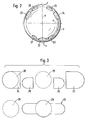
- two types of openings are provided, namely three circular openings 21, 22 and 23 or four openings, each of which has the shape of a horizontal rectangle, one narrow side of which is essentially semicircular is.
- the central opening 22 has a diameter which essentially corresponds to that of the water inflow channels opening into the ball valve seat and is larger than that of the two adjacent openings 21, 23 which are of equal size to one another.
- the four openings opposite the three circular openings 21, 22, 23 on the substantially same ball valve latitude are arranged in mirror image to a plane of symmetry x running through the actuating rod axis a 'and perpendicular to the pivot axis a, the distance between the two middle openings 25, 26 is larger than the diameter of the water inlet openings 28, 29 (FIG. 3) provided in the valve seat and all four openings are essentially semicircular on their narrow side facing away from the plane of symmetry x.
- the width of the outer openings 24 and 27 corresponds substantially to that of the aforementioned water inlet openings, while the length of the openings 24 and 27 is somewhat larger this diameter.
- the "bottom edges" of all seven openings 21 to 27 lie on the same ball plug latitude.
- an, for example, semi-ring-shaped opening can also be provided, which has two opening sections corresponding to the two inner openings 25 and 26.
- an opening 30 can also be provided (see FIG. 3), which is essentially circular in the middle and to which lateral oval halves with a smaller circular arc radius adjoin.
- the centers of the middle of the three circular openings 21, 22 and 23 and those of the semicircles of curvature of the larger of the remaining four openings 24, 25, 26 and 27 are also on the same ball plug width.
- This latitude y 'related to the axis of rotation a' running through the actuating rod 4 of the ball plug 5 corresponds to the latitude y related to the vertical axis b of the valve seat insert 2 on which the center points of the circular inlet openings 28, 29 of the water inflow channels opening into the valve seat lie.
- the distance between the center points of the aforementioned inlet openings is half the distance which is provided between the center points of the narrow sides of the outer of the four openings which are each arranged in mirror image and are semicircular.
- the actuating rod 4 can be aligned so that the latitudes of the ball head openings 21 to 23 or 30 and 24 to 27 and the water inlet openings 28, 29 cover.
- the actuating rod 4 By rotating the actuating rod 4 about its longitudinal axis a ', it is then possible to establish communication between one and / or the other of the two water inlet openings 28, 29 and the one and / or the other ball head openings, it being expedient to actuate the actuating rod 4 First of all turn so far that the larger of the three circular spherical head openings 22 (or the center of the integrally formed spherical head opening 30) coincides with one of the two inlet openings 28, 29.
- the actuating rod 4 can only be pivoted in the direction of arrow c (or in the opposite direction) or rotated together with the ball plug 5 about the axis of rotation a '.
- a pivoting in the direction of arrow c (or vice versa) has a change in the amount, the liquid flowing into the inside of the ball plug and a rotation about the axis of rotation a 'that other ball head openings than before with one and / or the other of the two water inlet openings 28, 29 cooperate, so that this changes the mixing ratio of the inflowing liquids.
- the liquid flowing into the ball plug 5 flows through the ball plug and leaves it on the opposite side through one and / or the other of the ball plug openings provided there, and further out via the outlet channel 10 provided in the valve seat insert 2, which is attached to it adjoining room 11 and the adjoining channels 12 and 13.
- the mixing valve shown corresponds entirely to the previously known mixing valves of the type mentioned at the outset.
- the mixing valve according to the invention it is possible to maintain the desired direction of rotation of the cap without great technical effort in such a connection situation. To do this, it is only necessary to remove the ball plug 5 from the valve seat insert 2 and to insert it again, offset by 180 °, so that the ball plug openings, which were previously used for water outlet, are now used for water inlet.
- the inlet opening 30 has narrow lateral extensions which can be brought into communication with the water inlet openings 28 and 29 of the valve seat 2 shown in dashed lines.
- the ball plug is rotated clockwise about the axis of rotation a '(FIG. 1) as far as it will go (seen from the inside of the plug towards the inlet openings 29 and 30 of the valve seat 2).
- the left opening 24 of the plug is open and the right cold water opening 29 is closed by the web between the openings 25 and 25 of the plug.
- the cold water opening 29 is opened through the circular middle part of the opening 30 of the plug, whereas the left part Warm water opening 28 is closed by the spherical wall.
- the rotatability of the actuating rod 4 is preferably limited so that it can only be rotated clockwise and counterclockwise by a certain amount.
- the actuating rod 4 is at least partially diamond-shaped in cross-section and guided in this region in a slot provided, for example, in the disk 18, the width of which essentially corresponds to the length of the smaller cross-sectional diagonal of the actuating rod 4.
- the point angle of the diamond on the larger cross-sectional diagonal preferably corresponds to the angle of rotation of the actuating rod 4.
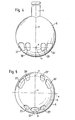
- the ball plug shown in FIGS. 4 and 5 differs from the ball plug shown in FIGS. 1 and 2 only in the form of the openings 24 'to 27' provided on one side thereof.
- these openings 24 'to 27' do not each have the shape of a lying rectangle, the narrow side of which is remote from the plane of symmetry x is essentially semicircular. Rather, the openings 24 'to 27' each have the shape of a trapezoid, the corners of which are rounded.
Landscapes
- Engineering & Computer Science (AREA)
- General Engineering & Computer Science (AREA)
- Mechanical Engineering (AREA)
- Multiple-Way Valves (AREA)
- Temperature-Responsive Valves (AREA)
- Valve-Gear Or Valve Arrangements (AREA)
Priority Applications (1)
| Application Number | Priority Date | Filing Date | Title |
|---|---|---|---|
| AT80100403T ATE3327T1 (de) | 1979-02-03 | 1980-01-26 | Mischventil fuer fluessigkeiten. |
Applications Claiming Priority (2)
| Application Number | Priority Date | Filing Date | Title |
|---|---|---|---|
| DE2904131A DE2904131C3 (de) | 1979-02-03 | 1979-02-03 | Mischventil für Flüssigkeiten |
| DE2904131 | 1979-02-03 |
Publications (2)
| Publication Number | Publication Date |
|---|---|
| EP0014399A1 true EP0014399A1 (fr) | 1980-08-20 |
| EP0014399B1 EP0014399B1 (fr) | 1983-05-11 |
Family
ID=6062099
Family Applications (1)
| Application Number | Title | Priority Date | Filing Date |
|---|---|---|---|
| EP80100403A Expired EP0014399B1 (fr) | 1979-02-03 | 1980-01-26 | Robinet mélangeur pour liquides |
Country Status (7)
| Country | Link |
|---|---|
| US (1) | US4352369A (fr) |
| EP (1) | EP0014399B1 (fr) |
| AT (1) | ATE3327T1 (fr) |
| DE (2) | DE2904131C3 (fr) |
| DK (1) | DK38780A (fr) |
| FI (1) | FI68302C (fr) |
| NO (1) | NO147572C (fr) |
Cited By (1)
| Publication number | Priority date | Publication date | Assignee | Title |
|---|---|---|---|---|
| EP0851161A3 (fr) * | 1992-03-12 | 1998-08-05 | Masco Corporation | Vanne à boisseau sphérique pour un robinet |
Families Citing this family (20)
| Publication number | Priority date | Publication date | Assignee | Title |
|---|---|---|---|---|
| DE3024518A1 (de) * | 1980-06-28 | 1982-01-28 | Hans Grohe Gmbh & Co Kg, 7622 Schiltach | Mischventil fuer fluessigkeiten |
| US4565218A (en) * | 1982-03-09 | 1986-01-21 | Yang Tai Her | Liquid mixing valve with single handle |
| US4584723A (en) * | 1983-06-29 | 1986-04-29 | Walter Hussauf | Fitting for connecting a plumbing faucet to plumbing pipes |
| US4562864A (en) * | 1983-11-02 | 1986-01-07 | Yang Tai Her | Single handle mixing valve with outlet selection |
| DE3419208A1 (de) * | 1984-05-23 | 1985-11-28 | Hans Grohe Gmbh & Co Kg, 7622 Schiltach | Steuereinsatz fuer sanitaere mischarmaturen |
| DE3533325A1 (de) * | 1985-09-18 | 1987-03-26 | Grohe Kg Hans | Mischventil fuer niederdruckwarmwasserspeicher |
| US4662388A (en) * | 1985-10-25 | 1987-05-05 | Eaton Plumbing Co., Inc. | Ball assembly for crossing hot and cold water channels in a faucet mixing valve housing |
| DE3541985A1 (de) * | 1985-11-28 | 1987-06-04 | Grohe Armaturen Friedrich | Mischbatterie |
| IT1232295B (it) * | 1989-09-22 | 1992-01-28 | Masco Gmbh | Rubinetto mischelatore ad otturatore sferico |
| AU638949B2 (en) * | 1989-10-10 | 1993-07-15 | Masco Corporation | Mixing valve with a ball control mechanism |
| RO112911B1 (ro) * | 1989-10-10 | 1998-01-30 | Masco Corp | Robinet de amestec, cu mecanism de comanda cu bila |
| US5507314A (en) * | 1991-06-11 | 1996-04-16 | Masco Corporation | Mixer valve having a ball valve element |
| US5615709A (en) * | 1992-12-11 | 1997-04-01 | Masco Corporation | Mixer valve having a ball valve element housed in a cartridge |
| US5613521A (en) * | 1993-10-08 | 1997-03-25 | Masco Corporation | Mixing valve having a ball valve cartridge and a lower insert member |
| CA95814S (en) | 1999-12-17 | 2002-05-31 | Hydraulic Eng S A | Ball for ball valves |
| US20060144689A1 (en) * | 2005-01-05 | 2006-07-06 | Paramount Leisure Industries, Inc. | Modular ozone generator |
| US20070039654A1 (en) * | 2005-08-22 | 2007-02-22 | Thomas Pinette | Spring energized lip seal faucet ball valve |
| US11788263B2 (en) * | 2017-10-13 | 2023-10-17 | Lily Herron | Valve enclosure |
| JP1657925S (fr) * | 2019-09-27 | 2020-04-20 | ||
| CN113483120B (zh) * | 2021-07-20 | 2023-04-28 | 上海化工研究院有限公司 | 一种拔杆式四位分配切换球阀 |
Citations (2)
| Publication number | Priority date | Publication date | Assignee | Title |
|---|---|---|---|---|
| US3674048A (en) * | 1970-04-09 | 1972-07-04 | Masco Corp | Mixing valve |
| FR2241031A1 (fr) * | 1973-08-13 | 1975-03-14 | Masco Corp |
Family Cites Families (7)
| Publication number | Priority date | Publication date | Assignee | Title |
|---|---|---|---|---|
| DE1600995U (de) | 1949-07-21 | 1950-02-09 | Peter Franken | Kerngehaeuseausstosser. |
| US2911009A (en) * | 1956-11-20 | 1959-11-03 | Stephen C Peplin | Mixing valve |
| US3056418A (en) * | 1959-05-04 | 1962-10-02 | Meagher James E | Mixing faucet |
| US3417783A (en) * | 1965-05-03 | 1968-12-24 | Meagher James E | Mixing valve |
| DE2246763A1 (de) * | 1972-09-23 | 1974-03-28 | Watts Ltd H & D | Mischventil |
| CH599491A5 (fr) * | 1976-02-25 | 1978-05-31 | Corpon P Von | |
| US4243063A (en) * | 1979-09-14 | 1981-01-06 | American Standard Inc. | Mixing valve |
-
1979
- 1979-02-03 DE DE2904131A patent/DE2904131C3/de not_active Expired
-
1980
- 1980-01-26 DE DE8080100403T patent/DE3063004D1/de not_active Expired
- 1980-01-26 AT AT80100403T patent/ATE3327T1/de not_active IP Right Cessation
- 1980-01-26 EP EP80100403A patent/EP0014399B1/fr not_active Expired
- 1980-01-30 DK DK38780A patent/DK38780A/da not_active Application Discontinuation
- 1980-01-31 US US06/117,415 patent/US4352369A/en not_active Expired - Lifetime
- 1980-02-01 FI FI800308A patent/FI68302C/fi not_active IP Right Cessation
- 1980-02-01 NO NO800264A patent/NO147572C/no unknown
Patent Citations (2)
| Publication number | Priority date | Publication date | Assignee | Title |
|---|---|---|---|---|
| US3674048A (en) * | 1970-04-09 | 1972-07-04 | Masco Corp | Mixing valve |
| FR2241031A1 (fr) * | 1973-08-13 | 1975-03-14 | Masco Corp |
Cited By (1)
| Publication number | Priority date | Publication date | Assignee | Title |
|---|---|---|---|---|
| EP0851161A3 (fr) * | 1992-03-12 | 1998-08-05 | Masco Corporation | Vanne à boisseau sphérique pour un robinet |
Also Published As
| Publication number | Publication date |
|---|---|
| NO147572B (no) | 1983-01-24 |
| DE2904131A1 (de) | 1980-08-07 |
| ATE3327T1 (de) | 1983-05-15 |
| NO147572C (no) | 1983-05-04 |
| NO800264L (no) | 1980-08-04 |
| US4352369A (en) | 1982-10-05 |
| FI68302C (fi) | 1985-08-12 |
| DE2904131B2 (de) | 1981-07-30 |
| DK38780A (da) | 1980-08-04 |
| FI800308A7 (fi) | 1980-08-04 |
| FI68302B (fi) | 1985-04-30 |
| DE3063004D1 (en) | 1983-06-16 |
| EP0014399B1 (fr) | 1983-05-11 |
| DE2904131C3 (de) | 1982-03-18 |
Similar Documents
| Publication | Publication Date | Title |
|---|---|---|
| EP0014399B1 (fr) | Robinet mélangeur pour liquides | |
| DE2359312C3 (de) | Mischventil | |
| DE2438855C2 (de) | Heiß- und Kaltwassermischventil | |
| DE2241638C3 (de) | Eingriff-Mischventil für Heiß- und Kaltwasser mit weitem Stellwinkel für die Mischungsregulierung | |
| EP0043076B1 (fr) | Robinet mélangeur pour liquides | |
| DE3500647A1 (de) | Eingriff-wasserhahn | |
| DE3903999A1 (de) | Sanitaeres mischventil | |
| DE69128485T2 (de) | Mischventil mit einem kugelfoermigen ventilement | |
| DE29817286U1 (de) | Reinigungsgerät | |
| DE2311840C2 (de) | Mischventil für zwei Fluidströmungen | |
| DE2630037A1 (de) | Kalt- und warmwassermischhahn mit zwei bedienungshebeln | |
| DE2417376A1 (de) | Mischventil | |
| DE3211618C2 (de) | Einhebel-Mischbatterie | |
| EP0012890B1 (fr) | Soupape stationnaire pour l'écoulement des eaux, en particulier pour installations sanitaires | |
| DE2246763A1 (de) | Mischventil | |
| DE2264815A1 (de) | Mischbatterie | |
| DE3211619C2 (de) | Einhebel-Mischbatterie | |
| DE2705165A1 (de) | Armatur, insbesondere mischbatterie mit handregulierung | |
| DE69107222T2 (de) | Selbstschliessender Mischer. | |
| DE3908009C2 (de) | Sanitärventil | |
| CH654389A5 (de) | Sanitaere einhebel-mischarmatur. | |
| EP0762029A2 (fr) | Soupape d'inversion pour connexion à conduites d'eau dans le domaine domestique et sanitaire | |
| DE2716831A1 (de) | Mischventil | |
| DE2050025B2 (de) | Eingriff Mischbatterie | |
| DE2737478A1 (de) | Einhebelmischbatterie |
Legal Events
| Date | Code | Title | Description |
|---|---|---|---|
| PUAI | Public reference made under article 153(3) epc to a published international application that has entered the european phase |
Free format text: ORIGINAL CODE: 0009012 |
|
| AK | Designated contracting states |
Designated state(s): AT BE CH DE FR GB IT LU NL SE |
|
| 17P | Request for examination filed |
Effective date: 19800930 |
|
| ITF | It: translation for a ep patent filed | ||
| GRAA | (expected) grant |
Free format text: ORIGINAL CODE: 0009210 |
|
| AK | Designated contracting states |
Designated state(s): AT BE CH DE FR GB IT LU NL SE |
|
| REF | Corresponds to: |
Ref document number: 3327 Country of ref document: AT Date of ref document: 19830515 Kind code of ref document: T |
|
| REF | Corresponds to: |
Ref document number: 3063004 Country of ref document: DE Date of ref document: 19830616 |
|
| ET | Fr: translation filed | ||
| PGFP | Annual fee paid to national office [announced via postgrant information from national office to epo] |
Ref country code: LU Payment date: 19840103 Year of fee payment: 5 |
|
| PG25 | Lapsed in a contracting state [announced via postgrant information from national office to epo] |
Ref country code: LU Free format text: LAPSE BECAUSE OF NON-PAYMENT OF DUE FEES Effective date: 19840131 |
|
| PLBE | No opposition filed within time limit |
Free format text: ORIGINAL CODE: 0009261 |
|
| STAA | Information on the status of an ep patent application or granted ep patent |
Free format text: STATUS: NO OPPOSITION FILED WITHIN TIME LIMIT |
|
| PGFP | Annual fee paid to national office [announced via postgrant information from national office to epo] |
Ref country code: SE Payment date: 19840331 Year of fee payment: 5 Ref country code: BE Payment date: 19840331 Year of fee payment: 5 |
|
| 26N | No opposition filed | ||
| PGFP | Annual fee paid to national office [announced via postgrant information from national office to epo] |
Ref country code: AT Payment date: 19860113 Year of fee payment: 7 |
|
| PG25 | Lapsed in a contracting state [announced via postgrant information from national office to epo] |
Ref country code: SE Effective date: 19860127 |
|
| PGFP | Annual fee paid to national office [announced via postgrant information from national office to epo] |
Ref country code: NL Payment date: 19860131 Year of fee payment: 7 |
|
| PG25 | Lapsed in a contracting state [announced via postgrant information from national office to epo] |
Ref country code: AT Effective date: 19870126 |
|
| BERE | Be: lapsed |
Owner name: HANS GROHE G.M.B.H. & CO. K.G. Effective date: 19870131 |
|
| PG25 | Lapsed in a contracting state [announced via postgrant information from national office to epo] |
Ref country code: NL Effective date: 19870801 |
|
| NLV4 | Nl: lapsed or anulled due to non-payment of the annual fee | ||
| PGFP | Annual fee paid to national office [announced via postgrant information from national office to epo] |
Ref country code: FR Payment date: 19890117 Year of fee payment: 10 |
|
| ITTA | It: last paid annual fee | ||
| PG25 | Lapsed in a contracting state [announced via postgrant information from national office to epo] |
Ref country code: BE Effective date: 19890131 |
|
| PGFP | Annual fee paid to national office [announced via postgrant information from national office to epo] |
Ref country code: GB Payment date: 19890131 Year of fee payment: 10 |
|
| PGFP | Annual fee paid to national office [announced via postgrant information from national office to epo] |
Ref country code: DE Payment date: 19890323 Year of fee payment: 10 |
|
| PGFP | Annual fee paid to national office [announced via postgrant information from national office to epo] |
Ref country code: CH Payment date: 19890405 Year of fee payment: 10 |
|
| PG25 | Lapsed in a contracting state [announced via postgrant information from national office to epo] |
Ref country code: GB Effective date: 19900126 |
|
| PG25 | Lapsed in a contracting state [announced via postgrant information from national office to epo] |
Ref country code: CH Effective date: 19900131 |
|
| GBPC | Gb: european patent ceased through non-payment of renewal fee | ||
| PG25 | Lapsed in a contracting state [announced via postgrant information from national office to epo] |
Ref country code: FR Effective date: 19900928 |
|
| REG | Reference to a national code |
Ref country code: CH Ref legal event code: PL |
|
| PG25 | Lapsed in a contracting state [announced via postgrant information from national office to epo] |
Ref country code: DE Effective date: 19901002 |
|
| REG | Reference to a national code |
Ref country code: FR Ref legal event code: ST |
|
| EUG | Se: european patent has lapsed |
Ref document number: 80100403.7 Effective date: 19861023 |