EP0014491A1 - Récipient à double paroi protégé contre la corrosion et l'explosion et procédé de fabrication dudit récipient - Google Patents
Récipient à double paroi protégé contre la corrosion et l'explosion et procédé de fabrication dudit récipient Download PDFInfo
- Publication number
- EP0014491A1 EP0014491A1 EP80200034A EP80200034A EP0014491A1 EP 0014491 A1 EP0014491 A1 EP 0014491A1 EP 80200034 A EP80200034 A EP 80200034A EP 80200034 A EP80200034 A EP 80200034A EP 0014491 A1 EP0014491 A1 EP 0014491A1
- Authority
- EP
- European Patent Office
- Prior art keywords
- wall
- plastic
- double
- wire mesh
- walled container
- Prior art date
- Legal status (The legal status is an assumption and is not a legal conclusion. Google has not performed a legal analysis and makes no representation as to the accuracy of the status listed.)
- Granted
Links
Images


Classifications
-
- B—PERFORMING OPERATIONS; TRANSPORTING
- B65—CONVEYING; PACKING; STORING; HANDLING THIN OR FILAMENTARY MATERIAL
- B65D—CONTAINERS FOR STORAGE OR TRANSPORT OF ARTICLES OR MATERIALS, e.g. BAGS, BARRELS, BOTTLES, BOXES, CANS, CARTONS, CRATES, DRUMS, JARS, TANKS, HOPPERS, FORWARDING CONTAINERS; ACCESSORIES, CLOSURES, OR FITTINGS THEREFOR; PACKAGING ELEMENTS; PACKAGES
- B65D90/00—Component parts, details or accessories for large containers
- B65D90/22—Safety features
- B65D90/46—Arrangements for carrying off, or preventing the formation of electrostatic charges
-
- B—PERFORMING OPERATIONS; TRANSPORTING
- B65—CONVEYING; PACKING; STORING; HANDLING THIN OR FILAMENTARY MATERIAL
- B65D—CONTAINERS FOR STORAGE OR TRANSPORT OF ARTICLES OR MATERIALS, e.g. BAGS, BARRELS, BOTTLES, BOXES, CANS, CARTONS, CRATES, DRUMS, JARS, TANKS, HOPPERS, FORWARDING CONTAINERS; ACCESSORIES, CLOSURES, OR FITTINGS THEREFOR; PACKAGING ELEMENTS; PACKAGES
- B65D90/00—Component parts, details or accessories for large containers
- B65D90/02—Wall construction
- B65D90/028—Wall construction hollow-walled, e.g. double-walled with spacers
Definitions
- the present invention relates to a double-walled container for a combustible medium, consisting of an outer container wall and a glass fiber-reinforced plastic wall which is arranged at a distance from it and at least partially provided with electrically conductive substances and faces the medium to reduce the risk of ignition and corrosion.
- the tightness of the plastic wall can be checked by physical measurement methods.
- Double-walled containers in particular tanks, are increasingly being used to store flammable liquids such as petrol, alcohol, toluene, etc.
- plastic double-jacket systems have proven themselves for several years. These have the advantage of high corrosion resistance and can also be bonded relatively easily gas and liquid-tight in concrete, metal or tanks made of organic substances.
- Such linings are difficult to apply in double-walled containers and cause sealing problems. In addition, they cannot be walked on or entail the risk of injuring or detaching the electrically conductive layer.
- the electrical resistance of the surface of the plastic walls can be reduced by means of electrically conductive lacquer layers.
- these have the disadvantages of poor adhesion to the substrate, poor and poor conductivity and inadequate chemical and mechanical resistance. For the same reason, walking through the tank cannot be held responsible.
- the invention has for its object in particular to provide a double-walled container of the type mentioned, which does not have the disadvantages of the known and which prevents the occurrence of disruptive or dangerous electrostatic charges on the surface of the plastic wall due to the low surface resistance in advance.
- the invention specified in claim 1 has the advantage of a type of Faraday cage in the surface of the plastic wall facing the medium to be stored and thus prevents the occurrence of electrical potential differences between mesh elements at any location in the container. Sinking in the wire mesh results in good mechanical fixation of the wire mesh, without impairing the mechanical stability and crack sensitivity of the plastic wall, and due to a large number of metallic contact points with the medium, the medium can be grounded optimally.
- the size of the individual wire meshes can be adapted to the flash point, the explosion limit, the ignition temperature, the minimum ignition energy and the physical state variables of the medium.
- Another criterion is the type of operational use, in particular the flow rate of the medium, the type of filling and pumping, and the choice of cleaning methods when the container is fully and / or partially emptied.
- the arrangement can be integrated into existing tank designs and does not in any way affect the usual leak monitoring methods used.
- the embodiment according to claim 2 allows the prefabrication of plastic walls and has proven itself especially in the construction of tank farms.
- the embodiment according to claim 3 results in particularly reliable tight walls and allows the introduction of mechanically pretensionable galvanic connections between the individual tracks and the connecting lines of the earth potential.
- the advantage of the embodiment according to claim 4 lies in the fact that reliable and easily manufactured double-wall systems result.
- the embodiment according to claim 5 increases the mechanical strength of the wall and allows safe access to tank rooms, which is particularly important for cleaning and monitoring purposes.
- the advantage of an embodiment designed according to claim 6 is the high effectiveness in terms of dissipating electrostatic charges.
- the layer structure described in claim 7 has proven itself particularly in large tank systems and is suitable for container walls of a wide variety of materials.
- the advantage of the embodiment listed in claim 8 is its high resistance to corrosion and insensitivity to many aggressive-acting explosive media.
- a container produced using the method set out in claim 9 results in surfaces that are easy to clean and the particular advantage of economy.
- the further variant according to claim 10 also enables the production of curved surfaces on construction sites.
- the invention or the method according to the invention can be combined with other systems for discharging electrical charges and opens up a large number of new applications opportunities.
- Fig. 1 denotes a wire mesh.
- This wire mesh 1 is flexible and sumped with at least one wire over half the wire circumference in a hardening plastic 3, which is part of a layered plastic wall 2.
- a sunk node 1a of a wire mesh can be seen from FIG.
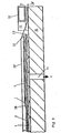
- FIG. 3 A preferred exemplary embodiment of a double-walled tank is shown in partial section in FIG. 3. This is a toluene container with a container wall 4 made of steel.
- the container wall 4 together with the plastic wall 2 held at a distance of a few millimeters, forms a double wall system.
- the plastic wall 2 has on it. an aluminum foil 5 on the side facing the container wall 4. Both walls 2 and 4 are spaced apart by pressure-resistant aluminum knobs 6.
- On the aluminum foil 5 is a glass fiber reinforced plastic (GRP) 7, which in turn is provided with individual webs of a wire mesh 1,1 '.
- GRP glass fiber reinforced plastic
- a busbar 8 connects individual tracks of the wire mesh 1, 1 'and is fixed via force introduction elements 9.
- the tank container is closed by a tank cap 10 fastened by means of screws (not shown).
- a grounding clamp 11 is screwed into the tank cap 10; an earth wire 12 is attached to this, which is led to the busbar 8 via a monitoring connection 13 (e.g. vacuum or protective gas connection).
- a monitoring connection 13 e.g. vacuum or protective gas connection.
- the aluminum foil 5 is likewise galvanically connected to the monitoring connection 13 by means of a contact disk 14 and is thus conductive to the grounding terminal 11.
- the steel jacket of the container wall 4 is connected to earth potential E in the present example.
- pure polyester 192 MV, Gurder company
- the aluminum knobs are reinforced with a hardening filler - inside - by quartz particles and UP resin in a mixed weight ratio of 52% to 48%.
- a flat plate made of corrosion-resistant steel of the chromium-nickel-molybdenum type (V4A) serves as the busbar 8
- Figures 4 and 5 represent overlaps of the wire nets 1 and 1 'and at the same time serve to explain the layer structure and the production of double-walled containers.
- an epoxy layer 22 (Etoplate, Gurder) is applied to the inside of the container wall 4 as protection against corrosion of the jacket and for the selective bonding of the pads 6 of the aluminum foil 5.
- the prefabricated and cut to length plastic wall 2 has on its upper side a loose bent piece of the wire mesh 1.
- the force introduction element 9 is placed with its flange 15 on a GRP spacer cam 24 and glued into a GRP laminate 25 with its star-shaped anchoring wires 16.
- the GRP laminate 25 with polyester putty 23 is leveled out to the GRP 7 1 of the wall 2 and then sanded.
- the wire mesh 1 which is in position I during assembly is now bent in the direction of the arrow in position II and electrically connected to its mutual end part via the busbar 8.
- the GRP 7 'in FIG. 5 are designed with butt joints 7a, which are positively connected by means of polyester cement 23; likewise the aluminum foil 5.
- the aluminum knobs 6 ' have a height of 5 mm; the wire mesh 1 'is merely sumped into polyester at its nodes 1a.
- the vacuum pump is switched off, the plastic films 28, 28 'are removed and there is a ready-to-install sheet of a tank wall.
- the bottoms of tanks are also produced in an analogous manner.
- a plastic hose made to the internal dimensions of the tank is advantageously placed on the coated wall 2 prepared in the tank, sealed on the edges, and centrally with the introduction of a vacuum connection, and thus the wire mesh 1 is blown in.
- the particular advantage of the method according to the invention is that commercial wire mesh is used can and that walls can also be produced on construction sites to suit individual needs.
- the invention described above is not limited to use in liquid tanks, but is suitable for any containers per se, for example also silos, laboratory containers, etc.
- the subject of the invention can also be used for the storage of solid bodies (plastic granules, etc.).
Landscapes
- Engineering & Computer Science (AREA)
- Mechanical Engineering (AREA)
- Filling Or Discharging Of Gas Storage Vessels (AREA)
- Details Of Rigid Or Semi-Rigid Containers (AREA)
- Prevention Of Electric Corrosion (AREA)
- Laminated Bodies (AREA)
- Preventing Corrosion Or Incrustation Of Metals (AREA)
Priority Applications (1)
| Application Number | Priority Date | Filing Date | Title |
|---|---|---|---|
| AT80200034T ATE907T1 (de) | 1979-01-19 | 1980-01-15 | Zuend- und korrosionsgesicherter doppelwandiger behaelter sowie verfahren zu dessen herstellung. |
Applications Claiming Priority (2)
| Application Number | Priority Date | Filing Date | Title |
|---|---|---|---|
| CH552/79 | 1979-01-19 | ||
| CH55279 | 1979-01-19 |
Publications (2)
| Publication Number | Publication Date |
|---|---|
| EP0014491A1 true EP0014491A1 (fr) | 1980-08-20 |
| EP0014491B1 EP0014491B1 (fr) | 1982-04-28 |
Family
ID=4189630
Family Applications (1)
| Application Number | Title | Priority Date | Filing Date |
|---|---|---|---|
| EP80200034A Expired EP0014491B1 (fr) | 1979-01-19 | 1980-01-15 | Récipient à double paroi protégé contre la corrosion et l'explosion et procédé de fabrication dudit récipient |
Country Status (3)
| Country | Link |
|---|---|
| EP (1) | EP0014491B1 (fr) |
| AT (1) | ATE907T1 (fr) |
| DE (2) | DE2904578A1 (fr) |
Cited By (13)
| Publication number | Priority date | Publication date | Assignee | Title |
|---|---|---|---|---|
| EP0069303A1 (fr) * | 1981-07-02 | 1983-01-12 | Neo Vac Aktiengesellschaft | Réservoir à double paroi et son procédé de fabrication |
| US4613922A (en) * | 1984-01-11 | 1986-09-23 | Neo Vac Aktiengesellschaft | Double-grounded wall tank, and method of its manufacture |
| DE8804373U1 (de) * | 1988-03-31 | 1988-05-26 | Ludwig, Klaus-Dieter, 76327 Pfinztal | Flüssigkeitsbehälter |
| GB2229134A (en) * | 1988-12-26 | 1990-09-19 | Benedito Salomao Cerqueira | Floors for containers and vehicle bodies in general |
| EP0436210A3 (en) * | 1990-01-03 | 1992-07-08 | Strabag Bau - Ag | Storage container |
| DE4446585A1 (de) * | 1994-03-25 | 1995-09-28 | Sotralentz Sa | Im Wege der Blasformgebung hergestellter Behälter aus thermoplastischem Kunststoff für die Aufnahme von sicherheitsbedürftigen fließfähigen Medien |
| NL1007018C2 (nl) * | 1997-09-11 | 1999-03-12 | Hollandse Signaalapparaten Bv | Vezel-kunststof composiet lichaam voor electromagnetische afscherming, voorzien van een elektrische contactstrip. |
| EP0949159A2 (fr) | 1998-04-06 | 1999-10-13 | Protechna S.A. | Récipient de transport et de stockage pour liquides |
| WO2000032394A1 (fr) * | 1998-12-01 | 2000-06-08 | New Lake International Limited | Revetement pour reservoir |
| WO2001068480A1 (fr) * | 2000-03-16 | 2001-09-20 | Basell Polyolefine Gmbh | Contenants et pieces en matiere plastique moules par soufflage presentant des proprietes antistatiques ameliorees |
| DE202014004902U1 (de) * | 2014-06-18 | 2015-09-21 | Fenotec Protec Gmbh | Elektrische Ableitung in Tankinnenhüllen für Benzin |
| EP2957526A1 (fr) | 2014-06-18 | 2015-12-23 | Fenotec Protec GmbH | Habillage interieur de citerne et son procede de fabrication |
| ES2565106A1 (es) * | 2014-09-29 | 2016-03-31 | Rafibra, S.L. | Método para detectar micro-poros en depósitos de doble capa |
Families Citing this family (1)
| Publication number | Priority date | Publication date | Assignee | Title |
|---|---|---|---|---|
| CN102502120B (zh) * | 2011-10-28 | 2013-10-16 | 詹玉顺 | 异型多舱多功能环保安全储罐 |
Citations (4)
| Publication number | Priority date | Publication date | Assignee | Title |
|---|---|---|---|---|
| DE1675316B2 (de) * | 1968-02-29 | 1972-05-04 | Hansen, Neuerburg & Co GmbH, 4300 Essen | Vorrichtung zur leckanzeige bei lagertanks |
| DE2334472B2 (de) * | 1973-07-06 | 1975-07-10 | Deutsche Geraetebau Gmbh, 4796 Salzkotten | Kunststoffbehälter für die unter- und überirdische Lagerung von Vergaserkraftstoffen mit einer Einrichtung zur Ableitung der statischen Elektrizität |
| DE2620225A1 (de) * | 1976-05-07 | 1977-11-10 | Tankbau Gmbh | Lagerbehaelter fuer fluessige brennstoffe |
| DE2719653A1 (de) * | 1977-05-03 | 1978-11-16 | Tankbau Gmbh | Lagerbehaelter fuer fluessige brennstoffe |
-
1979
- 1979-02-07 DE DE19792904578 patent/DE2904578A1/de not_active Withdrawn
-
1980
- 1980-01-15 AT AT80200034T patent/ATE907T1/de not_active IP Right Cessation
- 1980-01-15 EP EP80200034A patent/EP0014491B1/fr not_active Expired
- 1980-01-15 DE DE8080200034T patent/DE3060309D1/de not_active Expired
Patent Citations (4)
| Publication number | Priority date | Publication date | Assignee | Title |
|---|---|---|---|---|
| DE1675316B2 (de) * | 1968-02-29 | 1972-05-04 | Hansen, Neuerburg & Co GmbH, 4300 Essen | Vorrichtung zur leckanzeige bei lagertanks |
| DE2334472B2 (de) * | 1973-07-06 | 1975-07-10 | Deutsche Geraetebau Gmbh, 4796 Salzkotten | Kunststoffbehälter für die unter- und überirdische Lagerung von Vergaserkraftstoffen mit einer Einrichtung zur Ableitung der statischen Elektrizität |
| DE2620225A1 (de) * | 1976-05-07 | 1977-11-10 | Tankbau Gmbh | Lagerbehaelter fuer fluessige brennstoffe |
| DE2719653A1 (de) * | 1977-05-03 | 1978-11-16 | Tankbau Gmbh | Lagerbehaelter fuer fluessige brennstoffe |
Non-Patent Citations (1)
| Title |
|---|
| KUNSTSTOFFE, Band 59, Heft 12, 1969, Munchen D. SCHOLZ "Vermeiden der Zundgefahr an elektrostatisch aufgeladenen GFK-Oberflachen", Seiten 838-842 * Seite 842 * * |
Cited By (21)
| Publication number | Priority date | Publication date | Assignee | Title |
|---|---|---|---|---|
| EP0069303A1 (fr) * | 1981-07-02 | 1983-01-12 | Neo Vac Aktiengesellschaft | Réservoir à double paroi et son procédé de fabrication |
| US4613922A (en) * | 1984-01-11 | 1986-09-23 | Neo Vac Aktiengesellschaft | Double-grounded wall tank, and method of its manufacture |
| DE8804373U1 (de) * | 1988-03-31 | 1988-05-26 | Ludwig, Klaus-Dieter, 76327 Pfinztal | Flüssigkeitsbehälter |
| GB2229134A (en) * | 1988-12-26 | 1990-09-19 | Benedito Salomao Cerqueira | Floors for containers and vehicle bodies in general |
| GB2229134B (en) * | 1988-12-26 | 1992-09-16 | Benedito Salomao Cerqueira | Floors for containers and vehicle bodies in general |
| EP0436210A3 (en) * | 1990-01-03 | 1992-07-08 | Strabag Bau - Ag | Storage container |
| DE4446585A1 (de) * | 1994-03-25 | 1995-09-28 | Sotralentz Sa | Im Wege der Blasformgebung hergestellter Behälter aus thermoplastischem Kunststoff für die Aufnahme von sicherheitsbedürftigen fließfähigen Medien |
| DE4446585C2 (de) * | 1994-03-25 | 1998-07-16 | Sotralentz Sa | Im Wege der Blasformgebung hergestellter Behälter aus thermoplastischem Kunststoff für die Aufnahme von sicherheitsbedürftigen fließfähigen Medien |
| US6517658B1 (en) * | 1997-09-11 | 2003-02-11 | Thales Nederland B.V. | Fiber-resin composite body for providing electromagnetic shielding, comprising an electrical contact strip, and method for making same |
| NL1007018C2 (nl) * | 1997-09-11 | 1999-03-12 | Hollandse Signaalapparaten Bv | Vezel-kunststof composiet lichaam voor electromagnetische afscherming, voorzien van een elektrische contactstrip. |
| WO1999012727A1 (fr) * | 1997-09-11 | 1999-03-18 | Hollandse Signaalapparaten B.V. | Corps composite fibres-resine de blindage electromagnetique comprenant une bande de contact electrique et son procede de fabrication |
| EP0949159A2 (fr) | 1998-04-06 | 1999-10-13 | Protechna S.A. | Récipient de transport et de stockage pour liquides |
| US6156969A (en) * | 1998-04-06 | 2000-12-05 | Protechna S.A. | Transport and storage container for liquids |
| EP0949159A3 (fr) * | 1998-04-06 | 2002-04-10 | Protechna S.A. | Récipient de transport et de stockage pour liquides |
| DE19815082A1 (de) * | 1998-04-06 | 1999-10-14 | Protechna Sa | Transport- und Lagerbehälter für Flüssigkeiten |
| WO2000032394A1 (fr) * | 1998-12-01 | 2000-06-08 | New Lake International Limited | Revetement pour reservoir |
| WO2001068480A1 (fr) * | 2000-03-16 | 2001-09-20 | Basell Polyolefine Gmbh | Contenants et pieces en matiere plastique moules par soufflage presentant des proprietes antistatiques ameliorees |
| US6855388B2 (en) | 2000-03-16 | 2005-02-15 | Basell Polyolefine Gmbh | Blow moulded containers and moulded parts consisting of synthetic material and having improved antistatic properties |
| DE202014004902U1 (de) * | 2014-06-18 | 2015-09-21 | Fenotec Protec Gmbh | Elektrische Ableitung in Tankinnenhüllen für Benzin |
| EP2957526A1 (fr) | 2014-06-18 | 2015-12-23 | Fenotec Protec GmbH | Habillage interieur de citerne et son procede de fabrication |
| ES2565106A1 (es) * | 2014-09-29 | 2016-03-31 | Rafibra, S.L. | Método para detectar micro-poros en depósitos de doble capa |
Also Published As
| Publication number | Publication date |
|---|---|
| ATE907T1 (de) | 1982-05-15 |
| EP0014491B1 (fr) | 1982-04-28 |
| DE2904578A1 (de) | 1980-07-31 |
| DE3060309D1 (en) | 1982-06-09 |
Similar Documents
| Publication | Publication Date | Title |
|---|---|---|
| EP0014491A1 (fr) | Récipient à double paroi protégé contre la corrosion et l'explosion et procédé de fabrication dudit récipient | |
| EP0470321A1 (fr) | Réservoir et procédé pour sa fabrication | |
| EP0251045B1 (fr) | Couche étanche chimiquement résistante | |
| DE69309867T2 (de) | Äussere Schutzhülle für Metalllagerbehälter zur unterirdische Lagerung, insbesondere für Gasbehälter | |
| DE2063088A1 (de) | Biegsamer Stoffbehalter | |
| DE2648211A1 (de) | Isolierter behaelter fuer kryogene fluessigkeiten | |
| WO1981002562A1 (fr) | Citerne de stockage a double paroi comportant un manteau interieur en matiere plastique | |
| DE20104828U1 (de) | Verbindungssystem zur Befestigung einer flexiblen Kunststoffolie zur Leckschutzauskleidung an der Innenseite der Tankwandung eines Lagertanks | |
| DE3245462A1 (de) | Leitung aus bewehrtem beton und verfahren zu ihrer herstellung | |
| CH617148A5 (en) | Storage tank for liquid fuels | |
| CH399326A (de) | Tank | |
| DE4016324A1 (de) | Lagerbehaelter fuer fluessige und/oder feste chemische faellungsmittel aus gegen diese resistentem material | |
| DE202013102393U1 (de) | Kunststofffolie zur Innenauskleidung eines Tanks | |
| DE9109544U1 (de) | Lagerbehälter für brennbare Flüssigkeiten | |
| DE2358198A1 (de) | Verfahren zum elektrisch leitenden verbinden von gfk-teilen | |
| AT239710B (de) | Flüssigkeitsbehälter | |
| EP2957526B1 (fr) | Habillage interieur de citerne et son procede de fabrication | |
| EP0683113A1 (fr) | Dispositif indicateur de fuite pour la détection de fuites dans les parois de conteneurs | |
| DE2014296B2 (de) | Zusammengesetzte thermische isolierung und schutzbeschichtung | |
| DE8616698U1 (de) | Chemisch beständiger, flüssigkeitsdichter Belag | |
| DE7341620U (de) | Transparenter Tank aus glasfaserverstärktem Reaktionsharzformstoff | |
| DE2204452A1 (de) | Erdlagertank | |
| DE8425108U1 (de) | Innenverkleidung für doppelwandige Brennstofftanks | |
| DE202021001670U1 (de) | Bodenabschlussprofil zur Befestigung einer Auskleidungsfolie bei betonierten Rundbehältern | |
| DE1934274A1 (de) | Heizwasserspeicherbehaelter |
Legal Events
| Date | Code | Title | Description |
|---|---|---|---|
| PUAI | Public reference made under article 153(3) epc to a published international application that has entered the european phase |
Free format text: ORIGINAL CODE: 0009012 |
|
| AK | Designated contracting states |
Designated state(s): AT BE CH DE FR GB IT LU NL SE |
|
| 17P | Request for examination filed | ||
| ITF | It: translation for a ep patent filed | ||
| GRAA | (expected) grant |
Free format text: ORIGINAL CODE: 0009210 |
|
| AK | Designated contracting states |
Designated state(s): AT BE CH DE FR GB IT LU NL SE |
|
| REF | Corresponds to: |
Ref document number: 907 Country of ref document: AT Date of ref document: 19820515 Kind code of ref document: T |
|
| REF | Corresponds to: |
Ref document number: 3060309 Country of ref document: DE Date of ref document: 19820609 |
|
| PGFP | Annual fee paid to national office [announced via postgrant information from national office to epo] |
Ref country code: FR Payment date: 19901218 Year of fee payment: 12 |
|
| PGFP | Annual fee paid to national office [announced via postgrant information from national office to epo] |
Ref country code: SE Payment date: 19901219 Year of fee payment: 12 |
|
| PGFP | Annual fee paid to national office [announced via postgrant information from national office to epo] |
Ref country code: BE Payment date: 19901228 Year of fee payment: 12 |
|
| PGFP | Annual fee paid to national office [announced via postgrant information from national office to epo] |
Ref country code: AT Payment date: 19910107 Year of fee payment: 12 |
|
| PGFP | Annual fee paid to national office [announced via postgrant information from national office to epo] |
Ref country code: LU Payment date: 19910109 Year of fee payment: 12 |
|
| ITTA | It: last paid annual fee | ||
| PGFP | Annual fee paid to national office [announced via postgrant information from national office to epo] |
Ref country code: NL Payment date: 19910131 Year of fee payment: 12 |
|
| PGFP | Annual fee paid to national office [announced via postgrant information from national office to epo] |
Ref country code: GB Payment date: 19910301 Year of fee payment: 12 |
|
| EPTA | Lu: last paid annual fee | ||
| PG25 | Lapsed in a contracting state [announced via postgrant information from national office to epo] |
Ref country code: AT Effective date: 19920115 Ref country code: GB Effective date: 19920115 Ref country code: LU Free format text: LAPSE BECAUSE OF NON-PAYMENT OF DUE FEES Effective date: 19920115 |
|
| PG25 | Lapsed in a contracting state [announced via postgrant information from national office to epo] |
Ref country code: SE Effective date: 19920116 |
|
| PG25 | Lapsed in a contracting state [announced via postgrant information from national office to epo] |
Ref country code: BE Effective date: 19920131 |
|
| BERE | Be: lapsed |
Owner name: BORSARI & CO. Effective date: 19920131 |
|
| PG25 | Lapsed in a contracting state [announced via postgrant information from national office to epo] |
Ref country code: NL Effective date: 19920801 |
|
| GBPC | Gb: european patent ceased through non-payment of renewal fee | ||
| NLV4 | Nl: lapsed or anulled due to non-payment of the annual fee | ||
| PG25 | Lapsed in a contracting state [announced via postgrant information from national office to epo] |
Ref country code: FR Effective date: 19920930 |
|
| REG | Reference to a national code |
Ref country code: FR Ref legal event code: ST |
|
| PGFP | Annual fee paid to national office [announced via postgrant information from national office to epo] |
Ref country code: DE Payment date: 19940315 Year of fee payment: 15 |
|
| EUG | Se: european patent has lapsed |
Ref document number: 80200034.9 Effective date: 19920806 |
|
| PG25 | Lapsed in a contracting state [announced via postgrant information from national office to epo] |
Ref country code: DE Effective date: 19951003 |
|
| PGFP | Annual fee paid to national office [announced via postgrant information from national office to epo] |
Ref country code: CH Payment date: 19960228 Year of fee payment: 17 |
|
| PG25 | Lapsed in a contracting state [announced via postgrant information from national office to epo] |
Ref country code: CH Effective date: 19970131 |
|
| REG | Reference to a national code |
Ref country code: CH Ref legal event code: PL |
|
| PLBE | No opposition filed within time limit |
Free format text: ORIGINAL CODE: 0009261 |
|
| STAA | Information on the status of an ep patent application or granted ep patent |
Free format text: STATUS: NO OPPOSITION FILED WITHIN TIME LIMIT |