EP0014535A1 - Steuervorrichtungen für Heizsysteme - Google Patents
Steuervorrichtungen für Heizsysteme Download PDFInfo
- Publication number
- EP0014535A1 EP0014535A1 EP80300206A EP80300206A EP0014535A1 EP 0014535 A1 EP0014535 A1 EP 0014535A1 EP 80300206 A EP80300206 A EP 80300206A EP 80300206 A EP80300206 A EP 80300206A EP 0014535 A1 EP0014535 A1 EP 0014535A1
- Authority
- EP
- European Patent Office
- Prior art keywords
- switch
- heat
- valve
- operative
- time switch
- Prior art date
- Legal status (The legal status is an assumption and is not a legal conclusion. Google has not performed a legal analysis and makes no representation as to the accuracy of the status listed.)
- Granted
Links
Images


Classifications
-
- F—MECHANICAL ENGINEERING; LIGHTING; HEATING; WEAPONS; BLASTING
- F24—HEATING; RANGES; VENTILATING
- F24D—DOMESTIC- OR SPACE-HEATING SYSTEMS, e.g. CENTRAL HEATING SYSTEMS; DOMESTIC HOT-WATER SUPPLY SYSTEMS; ELEMENTS OR COMPONENTS THEREFOR
- F24D19/00—Details
- F24D19/10—Arrangement or mounting of control or safety devices
- F24D19/1006—Arrangement or mounting of control or safety devices for water heating systems
- F24D19/1009—Arrangement or mounting of control or safety devices for water heating systems for central heating
- F24D19/1015—Arrangement or mounting of control or safety devices for water heating systems for central heating using a valve or valves
-
- G—PHYSICS
- G04—HOROLOGY
- G04C—ELECTROMECHANICAL CLOCKS OR WATCHES
- G04C23/00—Clocks with attached or built-in means operating any device at preselected times or after preselected time-intervals
- G04C23/14—Mechanisms continuously running to relate the operation(s) to the time of day
- G04C23/26—Mechanisms continuously running to relate the operation(s) to the time of day for operating a number of devices at different times
- G04C23/28—Mechanisms continuously running to relate the operation(s) to the time of day for operating a number of devices at different times with contacts operated, or formed, by clock hands or elements of similar form
-
- G—PHYSICS
- G05—CONTROLLING; REGULATING
- G05D—SYSTEMS FOR CONTROLLING OR REGULATING NON-ELECTRIC VARIABLES
- G05D23/00—Control of temperature
- G05D23/19—Control of temperature characterised by the use of electric means
- G05D23/1902—Control of temperature characterised by the use of electric means characterised by the use of a variable reference value
- G05D23/1904—Control of temperature characterised by the use of electric means characterised by the use of a variable reference value variable in time
-
- G—PHYSICS
- G05—CONTROLLING; REGULATING
- G05D—SYSTEMS FOR CONTROLLING OR REGULATING NON-ELECTRIC VARIABLES
- G05D23/00—Control of temperature
- G05D23/19—Control of temperature characterised by the use of electric means
- G05D23/20—Control of temperature characterised by the use of electric means with sensing elements having variation of electric or magnetic properties with change of temperature
- G05D23/24—Control of temperature characterised by the use of electric means with sensing elements having variation of electric or magnetic properties with change of temperature the sensing element having a resistance varying with temperature, e.g. a thermistor
-
- H—ELECTRICITY
- H01—ELECTRIC ELEMENTS
- H01H—ELECTRIC SWITCHES; RELAYS; SELECTORS; EMERGENCY PROTECTIVE DEVICES
- H01H43/00—Time or time-programme switches providing a choice of time-intervals for executing one or more switching actions and automatically terminating their operation after the programme is completed
- H01H43/10—Time or time-programme switches providing a choice of time-intervals for executing one or more switching actions and automatically terminating their operation after the programme is completed with timing of actuation of contacts due to a part rotating at substantially constant speed
- H01H43/12—Time or time-programme switches providing a choice of time-intervals for executing one or more switching actions and automatically terminating their operation after the programme is completed with timing of actuation of contacts due to a part rotating at substantially constant speed stopping automatically after a single cycle of operation
Definitions
- This invention relates to control arrangements for heating systems having a plurality of heat outlets.
- present-day multi-outlet heating systems in particular central heating systems, in the most efficient and economical manner.
- present-day systems do not enable a bedroom to be heated only to a low temperature when unoccupied, and heated to a suitable higher temperature when it is about to be occupied.
- French Patent No. 2 264 256 discloses a system for heating hotels in which the heating in any room is turned on when the key for that room is removed from a central bank of hooks in a reception area and is turned off when the key is returned to its hook.
- Such an arrangement is disadvantageous in that (a) there is no provision for low level heating when the room is unoccupied, whereby rooms can become excessively cold if unoccupied for more than a short period, and (b) it cannot function properly in conjunction with a time switch arrangement often employed in heating systems to control the heat outputs of the heat outlets at different levels during a predetermined period of time, for instance 24 hours.
- DE-OS 2 530 855 discloses an arrangement in which heat levels in different rooms can be selectively controlled from a central location. However, it does not teach an arrangement in which selective central heat control and overall time switch control are provided in a manner in which such two forms of control are fully compatible and in particular in a manner in which an unoccupied room or group of rooms can be heated at a low level without having to effectively disconnect the time switch control from the heat outlet or outlets heating that room or group of rooms.
- a control arrangement for a heating system having a plurality of heat outlets comprising a central control means disposed remote from the heat outlets and including a time switch operative to cause the heat outlets to provide different heat outputs during different parts of a predetermined period of time, and respective thermostat means for each heat outlet to control the heat output thereof, characterised in that each thermostat means is capable of actuating the associated heat outlet at different temperatures, the time switch is operative to cause the thermostat means to actuate. the heat outlets at different temperatures at different times to provide the different heat outputs .
- the central control means includes, for each heat outlet, a manual switch coupling the time switch to the associated heat outlet via the associated thermostat means to manually set the heat output of the associated heat outlet, the time switch and each manual switch cooperating in such a manner that at least one may override the other so that the area heated by each heat outlet may be maintained at an appropriate temperature.
- the time switch is operative to cause each thermostat means to actuate the associated heat outlet at a higher temperature to provide high level heating or at a lower temperature to provide low level heating
- the manual switch when set for low level heating, overrides the time switch to provide low level heating whether the time switch calls for high or low level heating
- the time switch when the manual switch is set for high level heating, the time switch overrides the manual switch to provide high level heating only when the time switch calls for high level heating.
- the only control operation necessary is to set the manual switch associated with a particular room for low level heating when the room is unoccupied, in which case the manual switch overrides the time switch to provide low level heating at all times, and to set the manual switch for high level heating when the room is occupied, in which case the time switch overrides the manual switch and provides different levels of heating at different times.
- each thermostat means comprises a first thermostatic switch operative at the higher temperature and a second thermostatic switch operative at the lower temperature
- the time switch is operative to provide a voltage on one or the other of first and second conductors in accordance with whether the time switch calls for high or low level heating
- each manual switch comprises first and second contact sets connected, respectively, between the first conductor and the first thermostatic switch and between the second conductor and the second thermostatic switch
- each manual switch is so constructed that if the first contact set is closed to call for high level heating so also is the second contact set, whereas closure of the second contact set to call for low level heating does not cause closure of the first contact set
- a unidirectional current passing device connects the sides of the contact sets of each manual switch remote from the thermostatic switches such that if only the second contact set is closed to call for low level heating the second thermostatic switch will be energised from whichever of the first and second conductors that is energised.
- a control arrangement in accordance with the invention may be designed for controlling a heating system in which each heat outlet comprises one or more radiators through which, in use, a heating fluid flows.
- the arrangement may comprise a respective solenoid-operated valve for each heat outlet, each valve being energisable by the central control means via the thermostat means to actuate the heat outlet, and each valve comprising a coil, a plunger of magnetisable material movable within the coil on energisation of the coil, a valve member movable by the plunger away from a seati.ng when the coil is energised to open the valve, and an aperture formed through the valve member and communicating with a flow passage for the heating fluid whereby the same pressure subsists on each side of the valve member, the internal cross-sectional areas of a housing for the plunger and of the seating being the same whereby the valve member is precisely hydraulically balanced.
- the precise hydraulic balancing provided in this construction tends to make the valve operate quietly, which is a significant advantage in that the
- the aperture is preferably so dimensioned that it substantially restricts the flow of heating fluid through it as the plunger moves, thereby to hydraulically damp the plunger movement. Advantages of this construction are that the damping enhances quietness of operation and that the aperture performs the dual functions of damping and of providing the fluid flow communication enabling hydraulic balancing.
- the coil is preferably housed in the plunger, which provides for a simple construction.
- Each valve preferably comprises a body of magnetisable material associated with the coil and arranged to be contacted by the plunger when the valve is opened, whereby the current through the coil thereafter required to hold the valve open is less than that required to move the plunger to open the valve.
- the central control means is operative, via the thermostat means, to make a low voltage continuously available to the valves and to make a high voltage available to the valves sequentially, whereby each valve is supplied periodically with a relatively high current pulse enabling it to open and, thereafter, a relatively low current to hold the valve open.
- Supplying the high voltage to the valves sequentially, rather than as individual valves demand it, means that the current demand of the valves at any one time is substantially limited to the amount needed to open one valve.
- FIG. 1 shows a central heating system comprising a central heat source 100 connected to supply heat to a plurality of heat outlets 102, of which only two are shown, by means of heat delivery means schematically represented by lines 104.
- the heat outlets 102 are disposed remote from the source 100, for example in individual rooms of a hotel.
- the system will be hereinafter further described with reference to the case in which it is embodied as a hot water central heating system.
- the heat source 100 may comprise a hot water boiler
- each heat outlet 102 may comprise a radiator
- the heat delivery means 104 may comprise pipes interconnecting the boiler and radiators in any suitable and convenient manner.
- the system may be embodied in other forms.
- the heat outlets 102 may be convectors.
- the system may be embodied as a warm air central heating system, in which case the heat source 100 may comprise an air heating arrangement, the lines 104 may comprise ducts, and the heat outlets 102 may comprise outlets of the ducts.
- the illustrated system further comprises a respective local control means 106 for each heat outlet 102, each local control means being disposed generally at the location of the associated heat outlet.
- a central control means 108 is connected to each of the local control means 106 as schematically represented by lines 110, which may be electrical conductors.
- the central control means 108 is disposed remote from the heat outlets 102 at some convenient location or locations, for instance, in the case of a hotel, at or near the reception desk.
- the central control means 108 may be wholly disposed at one location or may have parts disposed at different locations.
- the location of the central control means 108 or a part or parts thereof may or may not be the same as the location of the central heat source 100.
- the functioning and construction of preferred forms of the local control means 106 and central control means 108 will become apparent as this description proceeds.
- the local control means 106 for each heat outlet 102 which is assumed to be a radiator, consists of or includes a solenoid-operated valve for controlling the radiator, the valve preferably being as illustrated in Figure 2, to which reference will now be made.
- the solenoid-operated valve shown in Figure 2 comprises a body 201 having an inlet passage 202 and an outlet passage 203 which may be isolated from the inlet passage by engagement of a valve member 204 with a seating 205.
- the valve member 204 comprises an end portion of a plunger 206 which.is made of a magnetisable material and acts as a solenoid armature.
- the plunger 206 is slidably mounted as a close fit in a sleeve 207 formed from non-magnetic material and screwed into a tapped hole in the body 201.as shown.
- a disc 208 of magnetisable material surrounds the sleeve 207, resting on a flanged portion 207a thereof, and an inverted cap 209, also of magnetisable material, is mounted on the disc 208 as shown, the disc 208 and cap 209 cooperating to form a housing of magnetisable material enclosing a coil 210 which surrounds the part of the sleeve 207 that is above the flanged portion 207a as shown in Figure 2.
- a projection 211 from the cap 209 enters the upper end of the sleeve 207 as shown in Figure 2 and is in sealing relationship therewith.
- the plunger 206 has a bore 212 therein, the bore extending from the upper end of the plunger as- shown in Figure 2 as far as an annular shoulder 213.
- a spring 214 is disposed within the bore 212 and acts between the projection 211 and the shoulder 213 to urge the valve member 204 against the seating 205 to close the valve.
- a bore 215, of smaller diameter than the bore 212, extends downwardly from the bore 212 below the shoulder 213, and a drilling 216 of even smaller diameter joins the bore 215 to the lower end of the plunger 206 defining the valve member 204.
- the drilling 216 ensures that the valve member 204 and plunger 206 are hydraulically balanced whereby forces exerted on the plunger are independent of the pressures subsisting in the inlet passage 202 and outlet passage 203.
- the internal diameters (and therefore the cross-sectional areas) of the . sleeve 207 and the seating 205 are the same, whereby the forces acting on the plunger 206 in each direction are identical so that precise hydraulic balancing is obtained.
- the valve described above may be opened to connect the inlet and outlet passages 202, 203 to allow hot water to flow through the radiator 102 by supplying a current to the coil 210 to cause the plunger 206 to rise to move the valve member 204 away from the seating 205 against the action of the spring 214. Because there is a gap between the upper end of the plunger 206 and the projection 211 when the valve is closed, relatively high current must be supplied to the coil 210 to open the valve. However, when the valve has opened the upper end of the plunger 206 abuts the projection 211, and since both the plunger 206 and cap 209 are of magnetisable material, the current then required to maintain the valve open is reduced to a relatively low value.
- the central control means 108 is operative to supply a relatively high current to the coil 210 to open the valve, when required, and then to supply a relatively low current to maintain it in the open condition.
- the drilling 216 thus serves the dual functions of providing hydraulic balance and of providing hydraulic damping to ensure quiet operation.
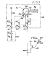
- FIG. 3 shows how the coils 210 of the solenoid valves of the various local control means 106 may be switched by the central control means 108.
- a source of a relatively low voltage VL is connected by a line 300 to the anodes of a plurality of diodes 302.
- the cathodes of the diodes are connected via manually-operable switches 303 disposed in the central control means 108, and via the-lines 110, which are in the form of electrical conductors, each to a respective one of the local control means 106, only one of which is shown.
- the associated line 110 is connected to one end of the coil 210 via a room thermostatic switch or thermostat 304 disposed in the room in which the associated radiator 102 is disposed to maintain a constant temperature in the room.
- a room thermostatic switch or thermostat 304 disposed in the room in which the associated radiator 102 is disposed to maintain a constant temperature in the room.
- a source of a relatively high voltage V E is connected to a slip ring 306.
- the diodes 302 prevent the high voltage source from feeding into the low voltage source.
- the arrangement of Figure 3 operates in the following manner.
- the switches 303 enable the radiators 102 to be centrally controlled, in that the valve of any radiator can only be energised to allow hot water to flow through the radiator if the associated switch 303 is closed.
- the associated switch 303 if the associated switch 303 is closed (and if the room thermostat 304 is also closed) a relatively low current will be continuously supplied thereto from the source of the low voltage VL and pulses of a relatively high current will be periodically supplied thereto from the source of the high voltage V H each time the brush 308 connects the associated contact 314 to such source via the slip ring 306.
- the duration of the high current pulse is sufficient to open the valve if it was previously closed.
- the low current from the source of the low voltage V L is sufficient to keep the valve open. Consequently, for each of the radiators 102, each time the associated switch 303 is closed and/or each time the associated room thermostat 304 calls for more heat by closing,the radiator valve will be opened when the next high current pulse is supplied to the associated coil 210 and will thereafter be maintained open by the continuous low current supply.
- slip ring 306, brush 308, motor 310 and contacts 314 in Figure 3 may be replaced by electronic circuitry designed to sequentially produce high current pulses as described.
- FIG 4 shows a possible modification of the arrangement of Figure 3.
- each of the contacts 314 is connected to the anode of the associated diode 302 via a transistor 410.
- the base of each transistor 410 is connected to the associated contact 314 and its emitter is connected to the anode of the associated diode 302.
- the collector of each transistor 410 is connected to the source of the high voltage V H .
- a contact 314 is connected by the brush 308 to the source of the high voltage V the associated transistor is switched from a non-conductive state to a conductive state in which it connects the voltage V H to the associated line 110.
- This modification reduces the current carried by the slip ring 306, brush 308 and contacts 314.
- the source of the low voltage V L is controlled by a time switch (not shown) whereby different levels of (and possibly no heating at all) are provided during different parts of a predetermined period of time, e.g. 24 hours.
- a time switch not shown
- different levels of (and possibly no heating at all) are provided during different parts of a predetermined period of time, e.g. 24 hours.
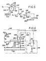
- a time switch 500 comprising a brush 502 rotationally driven by an electric motor 504, as shown schematically by a dotted line 506, at a speed of one revolution every 24 hours and constantly in contact with a slip ring 508.
- the brush 502 successively eng*ages each of a plurality of contacts 510 for a period of one or more hours in accordance with the shape of the contacts.
- the slip ring 508 is fed with the low voltage V L from the above-mentioned low voltage source.
- the low voltage is applied via a line 514 to the base of a transistor 516 which, since its collector is fed with the low voltage V L , then becomes conductive so that low voltage current can pass via lines 518 and 520 to a movable contact 522 of a switch 524.
- the switch 524 can be manually operated to connect the movable contact 522 to either of a pair of fixed contacts 526 or 528 of the switch which, in turn, are respectively connected to bus-bars 530 and 532; or can be operated, as shown, to disconnect the movable contact 522 so that no voltage is available at either of the bus-bars.
- one or the other of the bus-bare is energised according to the manual setting of the switch 524.
- one or the other of the bus-bars 530, 532, or neither of them can be energised via other transistor/switch circuits, like that described, interconnecting the other contacts 510 and the bus-bars 530, 532, whereby by setting the individual switches such as 524 the heating pattern for a 24 hour period can be programmed.
- this energisation of one or the other of the bus-bars 530, 532 determines whether a higher or a lower level of heating is available at each area being heated by the radiators 102, unless, in the case of each individual radiator, the level is limited by manual switching to the lower level. Also now to be described is means whereby the time switch 500 is operative to reduce the heating level of those areas which would otherwise be switched manually to the higher level.
- each radiator 102 there is provided in the central control means 108 a switching circuit as shown in the left-hand half of Figure 6.
- a diode 534 leads to a line 536 which, in turn, leads to a movable contact 538 of a manually-operable switch 540.
- a diode 542 connects the bus-bar 532 to a line 544 leading to another movable contact 546 of the switch 540.
- Switch 540 Fixed contacts 548, 550 of the switch 540 are connected by conductors 417, 415 to high and low temperature room thermostats or theimostatic switches 413, 411 operative to close at high and low temperatures respectively, the thermostats being in turn connected to the coil 210 of the valve of the associated radiator 102.
- the switches 413, 411 although shown as discrete switches, may be embodied as a single multi-level switch arrangement).
- a diode 552 connected as shown, allows current to flow from the line 536 to the line 544, but not vice-versa.
- the switch 540 is so designed that, if the contacts 538 and 548 are engaged, then so are the contacts 546 and 550, but that the contacts 546 and 550 can be engaged while the contacts 538,548 are not engaged. It is also possible for both pairs of contacts 538 , 548 and 546, -55 0 to be disengaged.
- the bus-bar 532 is energised by the time switch 500 instead of the bus-bar 530, current can pass via the diode 542 and the contacts 546 and 550 to the low level thermostat or thermostatic switch 411 and so the the solenoid valve if the temperature of that thermostat is below its set value.
- the diode 552 prevents current from passing from the bus-bar 532 to the high level thermostatic switch 413 even if the contacts 538 and 548 are engaged.
- the time switch 500 by energising only the bus-bar 532, overrides the manual switching to make available only low level heating.
- the circuit of Figures 5 and 6 includes the arrangement of the slip ring 306, brush 308, motor 310 and contacts 314 as described above with reference to Figure 3.
- the high voltage pulse from the associated one of the contacts 314 is directed to the line 544 of the low level heating circuit and also to the collector of a transistor 554, the base of which is connected to the bus-bar 530. So long as high level heating is called for by the time switch 540, the bus-bar 530 is energised and the transistor 554 remains conducting. When the time switch 500 calls for low level heating, the bus-bar 530 is not energised and the transistor 554 becomes non-conducting.
- the high voltage pulse can pass through the transistor 554 to the high level thermostatic switch 413 provided that the manual switching also calls for high level heating by closure of the contacts 538 and 548 of the switch 540.
- the transistor 554 is non-conducting and current cannot pass to the high level thermostatic switch 413 even if the contacts 538 and 548 are engaged, whereby the solenoid valve cannot be opened via the high level thermostatic switch 413.
- the single voltage V S is supplied by the time switch 500 to one or the other of the bus-bars 530, 532, in the manner previously described with reference to Figure 5, instead of the low voltage V L .
- the same voltage V S is supplied in pulses, in the manner previously described with reference to Figures 3 and 5, except that the transistor 554 is differently arranged in Figure 7 and the pulses are supplied to its base.
- the pulses are supplied directly to the line 554.
- resistors 700 and 702 which serve to reduce the current flowing through the solenoid valve coil while the solenoid valve is being held open.
- the pulses are supplied to the contacts..-538 and 546, by-passing the resistors 700, 702, and allowing full current to flow through the coil 210 so as to open the solenoid valve.
- the low voltage V L is supplied by the time switch 500 to one or the other of the bus-bars 530, 532 in the manner described above with reference to Figure 5. Further, for each radiator 102, the bus-bars 530, 532 are connected to the thermostatic switches 411, 413 by a switch 540, and diodes 534, 542 and 552 as described above with reference to Figure 6. However, the arrangement whereby pulses of the high voltage V H are supplied to the contact sets 538, 548 and 546, 550 of the individual switches 540 differs somewhat from that described with reference to Figure 6, as will now be described.
- each of the contacts 314 is connected to the associated switch 540 via a respective transistor 554.
- the slip ring 306, brush 308 and contacts 314, as described with reference to Figure 3 are replaced by a like arrangement comprising two slip rings 806, 808, a brush 810 and a plurality of contacts corresponding to the contacts 314 and designated, alternately, 812, and 814.
- Each contact 812 is connected to a switch 540 as shown, and the adjacent contact 814 in the direction of movement of the brush 810 is connected to the same switches, again as shown.
- the slip ring 806 is provided with radially outwardly extending projections 820 aligned with contacts 812.
- the slip ring 808 is provided with radially: inwardly extending projections 822 aligned with the contacts 814.
- the brush 810 is arranged to contact no part of the slip rings 806, 808 other than the projectiond . 820, 822.
- the brush 810 is driven by drive means (not shown) such that it dwells in line with em h projection 820, 822 in turn for long enough to supply a high voltage pulse to the radiator valve 210 of sufficient duration to open the valve; and is then rotated quickly to become in line with the next projection 820, 822.
- the above-mentioned transistors 802, 804 have their col- lectors connected to the source of the high voltage V H , their beses connected to the bus-bars 530 and 532, respectively, and their emitters connected to the slip rings 808, 806, respectively.
- the time switch 500 calls for low level heating, i.e. the bus-bar 532 is energised with the low voltage V L and the bus-bar 530 is not energised.
- the transistor 802 is held off, but the transistor 804 is switched on and current can flow from the high voltage source to the slip ring 806 and through the brush 810 and contact 814 to the low level thermostatic switch 411, when the brush 810 interconnects a projection 820 of the slip ring 806 and the contact 814 .
- the time switch 500 calls for high level heating by energising the bus-bar 530 instead of the bus-bar 532, the transistor 804 is cut off and current can flow from the high voltage source to the slip ring 808 and through the brush 810 and contact 812 to the high level thermostatic switch 413, when the brush 810 interconnects a projection 822 of the slip ring 808 and the contact 812.
- circuit of Figure 8 operates in similar manner to the circuit of Figure 6, except that due to the provision of the dual slip-ring arrangement as described it is possible to employ only two transistors 802, 804 for any number of radiators, rather than one transistor 554 per radiator.
- the thermostatic switches 411,413 may be embodied as a single multi-level switch arrangement instead of discrete switches.
- the discrete switches might be replaced by a thermal responsive device and an adjacent heater which when dissipating a high wattage causes the device to switch at a lower ambient temperature and which when dissipating a low wattage causes the device to switch at a higher temperature.
- a temperature dependent resistor e.g. a thermistor
Landscapes
- Physics & Mathematics (AREA)
- Engineering & Computer Science (AREA)
- General Physics & Mathematics (AREA)
- Automation & Control Theory (AREA)
- General Engineering & Computer Science (AREA)
- Chemical & Material Sciences (AREA)
- Combustion & Propulsion (AREA)
- Mechanical Engineering (AREA)
- Thermal Sciences (AREA)
- Control Of Resistance Heating (AREA)
- Yarns And Mechanical Finishing Of Yarns Or Ropes (AREA)
- Electrophonic Musical Instruments (AREA)
- Control Of Heat Treatment Processes (AREA)
- Lock And Its Accessories (AREA)
- General Induction Heating (AREA)
- Keying Circuit Devices (AREA)
- Electronic Switches (AREA)
- Selective Calling Equipment (AREA)
- Multiple-Way Valves (AREA)
Priority Applications (1)
| Application Number | Priority Date | Filing Date | Title |
|---|---|---|---|
| AT80300206T ATE6816T1 (de) | 1979-01-23 | 1980-01-22 | Steuervorrichtungen fuer heizsysteme. |
Applications Claiming Priority (2)
| Application Number | Priority Date | Filing Date | Title |
|---|---|---|---|
| GB7902393 | 1979-01-23 | ||
| GB7902393 | 1979-01-23 |
Publications (2)
| Publication Number | Publication Date |
|---|---|
| EP0014535A1 true EP0014535A1 (de) | 1980-08-20 |
| EP0014535B1 EP0014535B1 (de) | 1984-03-21 |
Family
ID=10502682
Family Applications (2)
| Application Number | Title | Priority Date | Filing Date |
|---|---|---|---|
| EP80300206A Expired EP0014535B1 (de) | 1979-01-23 | 1980-01-22 | Steuervorrichtungen für Heizsysteme |
| EP80300207A Expired EP0014096B1 (de) | 1979-01-23 | 1980-01-22 | Zeitschalter für Zentralheizungssysteme |
Family Applications After (1)
| Application Number | Title | Priority Date | Filing Date |
|---|---|---|---|
| EP80300207A Expired EP0014096B1 (de) | 1979-01-23 | 1980-01-22 | Zeitschalter für Zentralheizungssysteme |
Country Status (8)
| Country | Link |
|---|---|
| US (2) | US4580061A (de) |
| EP (2) | EP0014535B1 (de) |
| AT (2) | ATE6969T1 (de) |
| AU (2) | AU534750B2 (de) |
| CA (2) | CA1145012A (de) |
| DE (2) | DE3067078D1 (de) |
| HK (1) | HK32784A (de) |
| NZ (2) | NZ192675A (de) |
Cited By (3)
| Publication number | Priority date | Publication date | Assignee | Title |
|---|---|---|---|---|
| GB2173920A (en) * | 1985-04-17 | 1986-10-22 | John David Statham | Heating controller |
| FR2590723A1 (fr) * | 1985-11-25 | 1987-05-29 | Matsushita Electric Works Ltd | Interrupteur multipolaire commande par une horloge |
| EP0609036A1 (de) * | 1993-01-26 | 1994-08-03 | Miriam Thomas Ashworth | Steuerungs- und Betriebssystem |
Families Citing this family (8)
| Publication number | Priority date | Publication date | Assignee | Title |
|---|---|---|---|---|
| DE3272047D1 (en) * | 1982-01-08 | 1986-08-21 | Hans Gossi | Method for energy-saving water heating in residential buildings, particularly in large and medium sized buildings, and device for carrying out said method |
| DE3244603C1 (de) * | 1982-12-02 | 1984-06-28 | Dieter Gräßlin Feinwerktechnik, 7742 St Georgen | Vorrichtung fuer Thermostatventile,insbesondere zur Temperaturabsenkung Thermostat-gesteuerter Heizkoerper |
| US4886110A (en) * | 1988-02-22 | 1989-12-12 | Valera Electronics Inc. | HVAC zone control system |
| AUPM493394A0 (en) * | 1994-04-08 | 1994-05-05 | Kienko Pty Ltd | Solar hot water heating system |
| US7841837B2 (en) * | 2006-08-17 | 2010-11-30 | Zippy Technology Corp. | Cooling-fan rotation-speed control circuit |
| US7993338B2 (en) * | 2007-01-31 | 2011-08-09 | St. Jude Medical, Atrial Fibrillation Division, Inc. | Switching methods and apparatus |
| US9118186B2 (en) * | 2013-01-21 | 2015-08-25 | Peter F Nelson | Multiple outlet sequenced power strip |
| US10018366B2 (en) * | 2015-02-05 | 2018-07-10 | Intellihot, Inc. | Learning-based recirculation and temperature setpoint control system |
Citations (5)
| Publication number | Priority date | Publication date | Assignee | Title |
|---|---|---|---|---|
| FR2264256A1 (en) * | 1974-03-12 | 1975-10-10 | Sacrispeyre Jean Pierre | Electric room heating for hotel - has room door key operated switch at reception desk controlling radiator |
| DE2530855A1 (de) * | 1975-07-10 | 1977-01-20 | Hanns Dinkel | Verfahren zur zentralgesteuerten, vorprogrammierbaren einstellung von individuellen raumtemperaturen |
| FR2375554A1 (fr) * | 1976-12-22 | 1978-07-21 | Cem Comp Electro Mec | Procede de regulation d'un chauffage central individuel en immeuble collectif en fond + appoint |
| US4107466A (en) * | 1976-08-16 | 1978-08-15 | Letot, Incorporated | Individual room energy control system |
| DE2709732A1 (de) * | 1977-03-05 | 1978-09-07 | Erich Praekelt | Anordnung zur automatischen temperatursteuerung von raeumen |
Family Cites Families (8)
| Publication number | Priority date | Publication date | Assignee | Title |
|---|---|---|---|---|
| US2271727A (en) * | 1940-07-12 | 1942-02-03 | Automatic Signal Corp | Cyclic circuit controller |
| US2805331A (en) * | 1953-07-03 | 1957-09-03 | James E Wolford | Device for pre-tuning radio and television sets |
| US2905239A (en) * | 1954-09-30 | 1959-09-22 | Henry G Dietz Co Inc | Multiple circuit timer with adjustable time intervals |
| US2968746A (en) * | 1957-03-13 | 1961-01-17 | Oakton Engineering Corp | Programming mechanism |
| US3306348A (en) * | 1965-05-18 | 1967-02-28 | Singer Co | Air conditioning |
| US3586869A (en) * | 1969-09-08 | 1971-06-22 | Honeywell Inc | Sequencing control unit |
| US3886378A (en) * | 1973-11-08 | 1975-05-27 | Clemar Mfg Corp | Timing unit for connecting power sequentially to a plurality of stations |
| US4217646A (en) * | 1978-12-21 | 1980-08-12 | The Singer Company | Automatic control system for a building |
-
1980
- 1980-01-21 AU AU54769/80A patent/AU534750B2/en not_active Ceased
- 1980-01-21 CA CA000344051A patent/CA1145012A/en not_active Expired
- 1980-01-21 CA CA000344052A patent/CA1141009A/en not_active Expired
- 1980-01-21 AU AU54768/80A patent/AU532242B2/en not_active Ceased
- 1980-01-22 US US06/114,344 patent/US4580061A/en not_active Expired - Lifetime
- 1980-01-22 AT AT80300207T patent/ATE6969T1/de not_active IP Right Cessation
- 1980-01-22 NZ NZ192675A patent/NZ192675A/xx unknown
- 1980-01-22 NZ NZ192677A patent/NZ192677A/xx unknown
- 1980-01-22 AT AT80300206T patent/ATE6816T1/de not_active IP Right Cessation
- 1980-01-22 EP EP80300206A patent/EP0014535B1/de not_active Expired
- 1980-01-22 EP EP80300207A patent/EP0014096B1/de not_active Expired
- 1980-01-22 US US06/114,343 patent/US4323192A/en not_active Expired - Lifetime
- 1980-01-22 DE DE8080300206T patent/DE3067078D1/de not_active Expired
- 1980-01-22 DE DE8080300207T patent/DE3067304D1/de not_active Expired
-
1984
- 1984-04-12 HK HK327/84A patent/HK32784A/xx unknown
Patent Citations (5)
| Publication number | Priority date | Publication date | Assignee | Title |
|---|---|---|---|---|
| FR2264256A1 (en) * | 1974-03-12 | 1975-10-10 | Sacrispeyre Jean Pierre | Electric room heating for hotel - has room door key operated switch at reception desk controlling radiator |
| DE2530855A1 (de) * | 1975-07-10 | 1977-01-20 | Hanns Dinkel | Verfahren zur zentralgesteuerten, vorprogrammierbaren einstellung von individuellen raumtemperaturen |
| US4107466A (en) * | 1976-08-16 | 1978-08-15 | Letot, Incorporated | Individual room energy control system |
| FR2375554A1 (fr) * | 1976-12-22 | 1978-07-21 | Cem Comp Electro Mec | Procede de regulation d'un chauffage central individuel en immeuble collectif en fond + appoint |
| DE2709732A1 (de) * | 1977-03-05 | 1978-09-07 | Erich Praekelt | Anordnung zur automatischen temperatursteuerung von raeumen |
Cited By (4)
| Publication number | Priority date | Publication date | Assignee | Title |
|---|---|---|---|---|
| GB2173920A (en) * | 1985-04-17 | 1986-10-22 | John David Statham | Heating controller |
| GB2173920B (en) * | 1985-04-17 | 1989-06-28 | John David Statham | Improvements in and relating to heating systems |
| FR2590723A1 (fr) * | 1985-11-25 | 1987-05-29 | Matsushita Electric Works Ltd | Interrupteur multipolaire commande par une horloge |
| EP0609036A1 (de) * | 1993-01-26 | 1994-08-03 | Miriam Thomas Ashworth | Steuerungs- und Betriebssystem |
Also Published As
| Publication number | Publication date |
|---|---|
| EP0014096B1 (de) | 1984-04-04 |
| CA1145012A (en) | 1983-04-19 |
| NZ192677A (en) | 1983-07-29 |
| AU534750B2 (en) | 1984-02-16 |
| DE3067078D1 (en) | 1984-04-26 |
| DE3067304D1 (en) | 1984-05-10 |
| HK32784A (en) | 1984-04-19 |
| NZ192675A (en) | 1983-07-29 |
| US4580061A (en) | 1986-04-01 |
| AU532242B2 (en) | 1983-09-22 |
| EP0014096A1 (de) | 1980-08-06 |
| AU5476980A (en) | 1980-07-31 |
| AU5476880A (en) | 1980-07-31 |
| ATE6816T1 (de) | 1984-04-15 |
| EP0014535B1 (de) | 1984-03-21 |
| ATE6969T1 (de) | 1984-04-15 |
| US4323192A (en) | 1982-04-06 |
| CA1141009A (en) | 1983-02-08 |
Similar Documents
| Publication | Publication Date | Title |
|---|---|---|
| US5944098A (en) | Zone control for HVAC system | |
| US4323192A (en) | Control arrangements for heating circuits | |
| US5622221A (en) | Integrated zoning circulator with priority controller | |
| US6053416A (en) | Automatic hydronic zone valve and electric controls therefor | |
| US4201518A (en) | Recirculating fluid pump control system | |
| EP0033633B1 (de) | Stromdetektor | |
| US5386461A (en) | Telephone operated heating, ventilating and/or air conditioning | |
| US2437262A (en) | Electric heater thermostatic switch control | |
| US4908498A (en) | Control for delivery of power to heating elements | |
| US3934797A (en) | Individual room temperature control system | |
| EP0717332A1 (de) | Elektrisches Steuergerät für ein Stellorgan | |
| US4874926A (en) | Electric heating load management control | |
| US4485966A (en) | Pulsation device for a heating or cooling unit | |
| US4932466A (en) | Relay panel and system for controlling zoned heating and cooling systems | |
| GB2040515A (en) | Control Arrangements for Heating Systems | |
| US4147302A (en) | Home heating system control | |
| US4083397A (en) | Heating-cooling control system | |
| US4337891A (en) | Electric control device for a central heating boiler | |
| US3945564A (en) | Temperature control system | |
| GB2173920A (en) | Heating controller | |
| US4524908A (en) | Set-back thermostat assembly | |
| GB2148552A (en) | Central heating control system | |
| GB2090023A (en) | Central Heating Control System | |
| US3078874A (en) | Control for fluid mixing valve | |
| USRE28676E (en) | Control apparatus |
Legal Events
| Date | Code | Title | Description |
|---|---|---|---|
| PUAI | Public reference made under article 153(3) epc to a published international application that has entered the european phase |
Free format text: ORIGINAL CODE: 0009012 |
|
| AK | Designated contracting states |
Designated state(s): AT BE CH DE FR IT LU NL SE |
|
| 17P | Request for examination filed |
Effective date: 19810205 |
|
| ITF | It: translation for a ep patent filed | ||
| GRAA | (expected) grant |
Free format text: ORIGINAL CODE: 0009210 |
|
| AK | Designated contracting states |
Designated state(s): AT BE CH DE FR IT LU NL SE |
|
| REF | Corresponds to: |
Ref document number: 6816 Country of ref document: AT Date of ref document: 19840415 Kind code of ref document: T |
|
| REF | Corresponds to: |
Ref document number: 3067078 Country of ref document: DE Date of ref document: 19840426 |
|
| ET | Fr: translation filed | ||
| PG25 | Lapsed in a contracting state [announced via postgrant information from national office to epo] |
Ref country code: LU Free format text: LAPSE BECAUSE OF NON-PAYMENT OF DUE FEES Effective date: 19850131 |
|
| PLBE | No opposition filed within time limit |
Free format text: ORIGINAL CODE: 0009261 |
|
| STAA | Information on the status of an ep patent application or granted ep patent |
Free format text: STATUS: NO OPPOSITION FILED WITHIN TIME LIMIT |
|
| PGFP | Annual fee paid to national office [announced via postgrant information from national office to epo] |
Ref country code: DE Payment date: 19850312 Year of fee payment: 6 |
|
| 26N | No opposition filed | ||
| PGFP | Annual fee paid to national office [announced via postgrant information from national office to epo] |
Ref country code: NL Payment date: 19860131 Year of fee payment: 7 |
|
| PGFP | Annual fee paid to national office [announced via postgrant information from national office to epo] |
Ref country code: AT Payment date: 19860730 Year of fee payment: 7 |
|
| PG25 | Lapsed in a contracting state [announced via postgrant information from national office to epo] |
Ref country code: DE Effective date: 19861001 |
|
| PG25 | Lapsed in a contracting state [announced via postgrant information from national office to epo] |
Ref country code: AT Effective date: 19870122 |
|
| PG25 | Lapsed in a contracting state [announced via postgrant information from national office to epo] |
Ref country code: NL Effective date: 19870801 |
|
| NLV4 | Nl: lapsed or anulled due to non-payment of the annual fee | ||
| PG25 | Lapsed in a contracting state [announced via postgrant information from national office to epo] |
Ref country code: SE Effective date: 19880123 |
|
| PG25 | Lapsed in a contracting state [announced via postgrant information from national office to epo] |
Ref country code: CH Effective date: 19880131 |
|
| BERE | Be: lapsed |
Owner name: PLYMPTON PATENTS LTD Effective date: 19880131 |
|
| PG25 | Lapsed in a contracting state [announced via postgrant information from national office to epo] |
Ref country code: FR Free format text: LAPSE BECAUSE OF NON-PAYMENT OF DUE FEES Effective date: 19880930 |
|
| REG | Reference to a national code |
Ref country code: CH Ref legal event code: PL |
|
| REG | Reference to a national code |
Ref country code: FR Ref legal event code: ST |
|
| PG25 | Lapsed in a contracting state [announced via postgrant information from national office to epo] |
Ref country code: BE Effective date: 19890131 |
|
| EUG | Se: european patent has lapsed |
Ref document number: 80300206.2 Effective date: 19880913 |